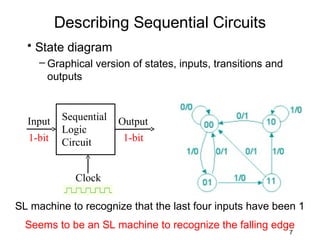
EET 3350 Digital Systems Design

        John Wakerly
      Chapter 7: 7.1 – 7.2

         Sequential Circuits
            Flip-Flops


                                  1
Combinational Logic Circuits
• Output set depends
  only on the current        n                     m
  input set
• If the input(s) change,
  the output(s) may
  change
• History of the input
  behavior is not           binary values,
  important to the future   an n-bit binary
  output behavior           number
                                           binary values,
                                           an m-bit binary
                                           number
                                                       2
Sequential Logic Circuits
• Output depends on
  current input and
                               n                   m
  history of past inputs
• Information about the
  past behavior (history)
  of the input(s) is held in
  memory
• Memory is finite,
  holding “just enough”
  information as defined
                                   Size of memory depends
  by design specification          on how much history we
                                   need to know.
                                                     3
Sequential Logic Circuits
• Some of the CL outputs
  are used to control the
                                 n   m
  memory elements
• Outputs from the
  memory elements are
  provided as inputs to
  the CL circuit
  – this is a form of feedback
• Memory may also have
  an external “clock”
  signal to control when
  changes can occur
                                     4
Sequential Logic Circuits
• The addition of the
  “extra” inputs and
                               n     m
  outputs doesn’t change
  the basic concepts
  associated with the CL
  part of the circuit
  – it just has more signals
• Our approach to
  designing the CL circuit
  is the same as always
• Need to design the
  memory part
                                     5
Sequential Logic Circuits
• Memory output is
  considered the circuit’s
                            n                          m
  “current state” – a
  numerical label
• State embodies all the
  information about the i                                    j
  past needed to define the
  current output
  – State variables, one or
    more bits of information
  – Present state, now, waiting    binary values, an i-bit or
  – Next state, next, with clock   j-bit binary number

                                                         6
Describing Sequential Circuits
  • State diagram
     – Graphical version of states, inputs, transitions and
       outputs


  Input    Sequential   Output
           Logic
  1-bit    Circuit      1-bit


              Clock

SL machine to recognize that the last four inputs have been 1
  Seems to be an SL machine to recognize the falling edge
                                                              7
Describing Sequential Circuits
• State table
  – For each current-state, specify next-state(s) as a
    function of the present inputs
  – For each current-state, specify the output(s) as a
    function of the present inputs


                                                         8
Describing Sequential Circuits
• State table
  – Alternate format


   More about states, tables and diagrams later.

                                                   9
Describing Sequential Circuits
• State table
  – Alternate format


   More about states, tables and diagrams later.

                                                   9

Sequential Circuits - Flip Flops (Part 1)

  • 1.
    EET 3350 DigitalSystems Design John Wakerly Chapter 7: 7.1 – 7.2 Sequential Circuits Flip-Flops 1
  • 2.
    Combinational Logic Circuits •Output set depends only on the current n m input set • If the input(s) change, the output(s) may change • History of the input behavior is not binary values, important to the future an n-bit binary output behavior number binary values, an m-bit binary number 2
  • 3.
    Sequential Logic Circuits •Output depends on current input and n m history of past inputs • Information about the past behavior (history) of the input(s) is held in memory • Memory is finite, holding “just enough” information as defined Size of memory depends by design specification on how much history we need to know. 3
  • 4.
    Sequential Logic Circuits •Some of the CL outputs are used to control the n m memory elements • Outputs from the memory elements are provided as inputs to the CL circuit – this is a form of feedback • Memory may also have an external “clock” signal to control when changes can occur 4
  • 5.
    Sequential Logic Circuits •The addition of the “extra” inputs and n m outputs doesn’t change the basic concepts associated with the CL part of the circuit – it just has more signals • Our approach to designing the CL circuit is the same as always • Need to design the memory part 5
  • 6.
    Sequential Logic Circuits •Memory output is considered the circuit’s n m “current state” – a numerical label • State embodies all the information about the i j past needed to define the current output – State variables, one or more bits of information – Present state, now, waiting binary values, an i-bit or – Next state, next, with clock j-bit binary number 6
  • 7.
    Describing Sequential Circuits • State diagram – Graphical version of states, inputs, transitions and outputs Input Sequential Output Logic 1-bit Circuit 1-bit Clock SL machine to recognize that the last four inputs have been 1 Seems to be an SL machine to recognize the falling edge 7
  • 8.
    Describing Sequential Circuits •State table – For each current-state, specify next-state(s) as a function of the present inputs – For each current-state, specify the output(s) as a function of the present inputs 8
  • 9.
    Describing Sequential Circuits •State table – Alternate format More about states, tables and diagrams later. 9
  • 10.
    Describing Sequential Circuits •State table – Alternate format More about states, tables and diagrams later. 9