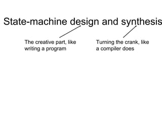
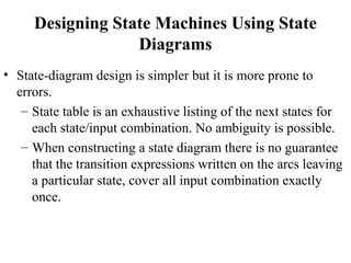
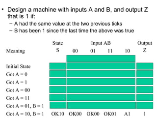
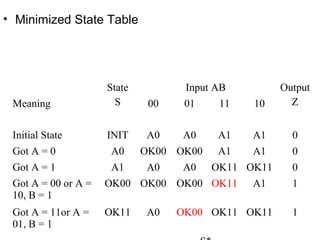
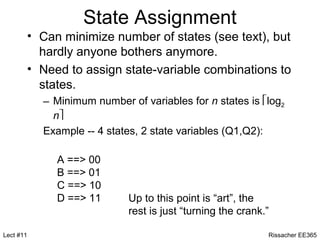
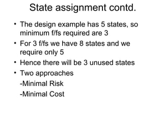
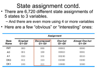
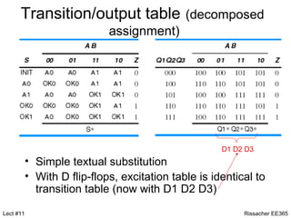
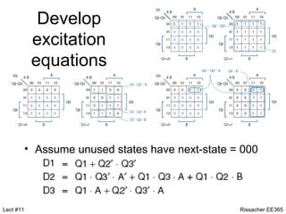
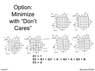
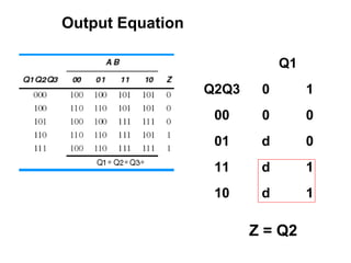
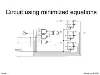
State-machine design and synthesis
    The creative part, like   Turning the crank, like
    writing a program         a compiler does
Designing State Machines Using State
                  Diagrams
• State-diagram design is simpler but it is more prone to
  errors.
   – State table is an exhaustive listing of the next states for
     each state/input combination. No ambiguity is possible.
   – When constructing a state diagram there is no guarantee
     that the transition expressions written on the arcs leaving
     a particular state, cover all input combination exactly
     once.
Designing State Machines Using State
                   Diagrams
• Mutual exclusion: For each state the logical product of each
  pair of transition expression on arcs leaving that state
  should be zero. If there are n arcs then there are n(n-1)/2
  logical products to evaluate
• All inclusion: For each state the logical sum of the transition
  expressions on all arcs leaving the state should be one.
• A state table guarantees mutual exclusion and all inclusion
• A state diagram needs to be verified for mutual exclusion
  and all inclusion so that there is no ambiguity.
• Design a machine with inputs A and B, and output Z
  that is 1 if:
  – A had the same value at the two previous ticks
  – B has been 1 since the last time the above was true

                     State          Input AB              Output
 Meaning               S      00    01     11      10       Z


 Initial State       INIT    A0     A0     A1     A1        0
 Got A = 0           A0      OK00 OK00     A1     A1        0
 Got A = 1           A1      A0     A0    OK11 OK11         0
 Got A = 00          OK00 OK00 OK00 OK01          A1        1
 Got A = 11          OK11    A0    OK10 OK11 OK11           1
 Got A = 01, B = 1   OK01    A0    OK10 OK11 OK11           1
 Got A = 10, B = 1   OK10 OK00 OK00 OK01          A1        1
• Minimized State Table


                     State          Input AB         Output
 Meaning               S      00    01    11   10      Z


 Initial State       INIT    A0    A0     A1   A1      0
 Got A = 0           A0      OK00 OK00    A1   A1      0
 Got A = 1           A1      A0    A0    OK11 OK11     0
 Got A = 00 or A =   OK00 OK00 OK00 OK11       A1      1
 10, B = 1
 Got A = 11or A =    OK11    A0    OK00 OK11 OK11      1
 01, B = 1
State Assignment
           • Can minimize number of states (see text), but
             hardly anyone bothers anymore.
           • Need to assign state-variable combinations to
             states.
             – Minimum number of variables for n states is log2
               n
             Example -- 4 states, 2 state variables (Q1,Q2):

                A ==> 00
                B ==> 01
                C ==> 10
                D ==> 11       Up to this point is “art”, the
                               rest is just “turning the crank.”

Lect #11                                                       Rissacher EE365
State assignment contd.
• The design example has 5 states, so
  minimum f/fs required are 3
• For 3 f/fs we have 8 states and we
  require only 5
• Hence there will be 3 unused states
• Two approaches
  -Minimal Risk
  -Minimal Cost
Minimal Risk
• All unused states are identified and explicit next
  state entries are made so that, for any input
  combination the unused states will go to the
  ‘initial’, ‘idle’ or ‘safe’ state
                  Minimal Cost
• All unused states are identified and next state
  entries are marked as ‘don’t cares’. In most
  cases this simplifies the excitation logic.
  However, the machine’s behavior if it enters an
  unused state may be pretty weird
Guidelines for state assignments
• Choose an initial coded state into which the
  machine can easily be forced at reset (00.. Or
  11..)
• Minimize the number of state variables that
  change on each transition
• Maximize the number of state variables that do
  not change in a group of related states. ( a
  group of states in which most of the transitions
  stay in the group)
Guidelines for state assignments
• Exploit symmetries in the problem specification
  and the corresponding symmetries in the state
  table.
• If there are unused states then use the ‘best’
  available states
• Decompose the set of states into individual bits
  or fields, where they have a well defined
  meaning with respect to the input effects or
  output behavior
• Consider more than the minimum number of
  state variables
State assignment contd.
• There are 6,720 different state assignments of
  5 states to 3 variables.
  – And there are even more using 4 or more variables
• Here are a few “obvious” or “interesting” ones:
One–hot assignment
• It uses 1 bit per state
• Simple
• Each f/f needs to be set to ‘1’ for transitions in
  only one state
• More number of f/fs
• Usually used for a machine with S states that is
  required to have a set of 1 out-of-S coded
  outputs indicating its current state. The one-hot
  -coded f/f outputs can be used directly for this
  purpose, with no additional combinational
  output logic
Almost One–hot assignment
• It uses a ‘no-hot’ combination for the initial state
Reasons
  -Easy to initialize most storage devices to 0
  -Initial state in particular is usually not visited
  once the machine gets going
Incorporation of some guidelines
• Initial state is 000 which is easy to force using
  Reset signal
• Q1 is used to indicate whether the machine is
  in INIT state or not
  -Q1 = 0 implies INIT state
  -Q1 = 1 implies non-INIT states
• Q2 indicates that the conditions for a ‘1’ output
  are satisfied in the current state.
  -Q2 = 0 for A0, A1 states
  -Q2 = 1 for OK0, OK1 states
Incorporation of some guidelines
• Q3 indicates the previous value of A.
  -Q3 = 0 for OK0, A0 states
  -Q3 = 1 for OK1, A1 states

• By decomposing the state bits meanings in this
  way, we can expect the next state and output
  logic to be simpler than in a ‘random’
  assignment
Transition/output table (decomposed
                             assignment)


                                                      D1 D2 D3
           • Simple textual substitution
           • With D flip-flops, excitation table is identical to
             transition table (now with D1 D2 D3)

Lect #11                                                   Rissacher EE365
Develop
            excitation
            equations


           • Assume unused states have next-state = 000


Lect #11                                           Rissacher EE365
Option:
            Minimize
           with “Don’t
             Cares”


                    D1 = 1
                    D2 = Q1 • Q3´ • A´ + Q3 • A + Q2 • B
                    D3 = A

Lect #11                                            Rissacher EE365
Output Equation

                              Q1
                  Q2Q3    0        1
                   00     0        0
                   01     d        0
                   11     d        1
                   10     d        1

                         Z = Q2
Circuit using minimized equations


Lect #11                        Rissacher EE365

State Machine Design and Synthesis

  • 1.
    State-machine design andsynthesis The creative part, like Turning the crank, like writing a program a compiler does
  • 2.
    Designing State MachinesUsing State Diagrams • State-diagram design is simpler but it is more prone to errors. – State table is an exhaustive listing of the next states for each state/input combination. No ambiguity is possible. – When constructing a state diagram there is no guarantee that the transition expressions written on the arcs leaving a particular state, cover all input combination exactly once.
  • 3.
    Designing State MachinesUsing State Diagrams • Mutual exclusion: For each state the logical product of each pair of transition expression on arcs leaving that state should be zero. If there are n arcs then there are n(n-1)/2 logical products to evaluate • All inclusion: For each state the logical sum of the transition expressions on all arcs leaving the state should be one. • A state table guarantees mutual exclusion and all inclusion • A state diagram needs to be verified for mutual exclusion and all inclusion so that there is no ambiguity.
  • 4.
    • Design amachine with inputs A and B, and output Z that is 1 if: – A had the same value at the two previous ticks – B has been 1 since the last time the above was true State Input AB Output Meaning S 00 01 11 10 Z Initial State INIT A0 A0 A1 A1 0 Got A = 0 A0 OK00 OK00 A1 A1 0 Got A = 1 A1 A0 A0 OK11 OK11 0 Got A = 00 OK00 OK00 OK00 OK01 A1 1 Got A = 11 OK11 A0 OK10 OK11 OK11 1 Got A = 01, B = 1 OK01 A0 OK10 OK11 OK11 1 Got A = 10, B = 1 OK10 OK00 OK00 OK01 A1 1
  • 5.
    • Minimized StateTable State Input AB Output Meaning S 00 01 11 10 Z Initial State INIT A0 A0 A1 A1 0 Got A = 0 A0 OK00 OK00 A1 A1 0 Got A = 1 A1 A0 A0 OK11 OK11 0 Got A = 00 or A = OK00 OK00 OK00 OK11 A1 1 10, B = 1 Got A = 11or A = OK11 A0 OK00 OK11 OK11 1 01, B = 1
  • 6.
    State Assignment • Can minimize number of states (see text), but hardly anyone bothers anymore. • Need to assign state-variable combinations to states. – Minimum number of variables for n states is log2 n Example -- 4 states, 2 state variables (Q1,Q2): A ==> 00 B ==> 01 C ==> 10 D ==> 11 Up to this point is “art”, the rest is just “turning the crank.” Lect #11 Rissacher EE365
  • 7.
    State assignment contd. •The design example has 5 states, so minimum f/fs required are 3 • For 3 f/fs we have 8 states and we require only 5 • Hence there will be 3 unused states • Two approaches -Minimal Risk -Minimal Cost
  • 8.
    Minimal Risk • Allunused states are identified and explicit next state entries are made so that, for any input combination the unused states will go to the ‘initial’, ‘idle’ or ‘safe’ state Minimal Cost • All unused states are identified and next state entries are marked as ‘don’t cares’. In most cases this simplifies the excitation logic. However, the machine’s behavior if it enters an unused state may be pretty weird
  • 9.
    Guidelines for stateassignments • Choose an initial coded state into which the machine can easily be forced at reset (00.. Or 11..) • Minimize the number of state variables that change on each transition • Maximize the number of state variables that do not change in a group of related states. ( a group of states in which most of the transitions stay in the group)
  • 10.
    Guidelines for stateassignments • Exploit symmetries in the problem specification and the corresponding symmetries in the state table. • If there are unused states then use the ‘best’ available states • Decompose the set of states into individual bits or fields, where they have a well defined meaning with respect to the input effects or output behavior • Consider more than the minimum number of state variables
  • 11.
    State assignment contd. •There are 6,720 different state assignments of 5 states to 3 variables. – And there are even more using 4 or more variables • Here are a few “obvious” or “interesting” ones:
  • 12.
    One–hot assignment • Ituses 1 bit per state • Simple • Each f/f needs to be set to ‘1’ for transitions in only one state • More number of f/fs • Usually used for a machine with S states that is required to have a set of 1 out-of-S coded outputs indicating its current state. The one-hot -coded f/f outputs can be used directly for this purpose, with no additional combinational output logic
  • 13.
    Almost One–hot assignment •It uses a ‘no-hot’ combination for the initial state Reasons -Easy to initialize most storage devices to 0 -Initial state in particular is usually not visited once the machine gets going
  • 14.
    Incorporation of someguidelines • Initial state is 000 which is easy to force using Reset signal • Q1 is used to indicate whether the machine is in INIT state or not -Q1 = 0 implies INIT state -Q1 = 1 implies non-INIT states • Q2 indicates that the conditions for a ‘1’ output are satisfied in the current state. -Q2 = 0 for A0, A1 states -Q2 = 1 for OK0, OK1 states
  • 15.
    Incorporation of someguidelines • Q3 indicates the previous value of A. -Q3 = 0 for OK0, A0 states -Q3 = 1 for OK1, A1 states • By decomposing the state bits meanings in this way, we can expect the next state and output logic to be simpler than in a ‘random’ assignment
  • 16.
    Transition/output table (decomposed assignment) D1 D2 D3 • Simple textual substitution • With D flip-flops, excitation table is identical to transition table (now with D1 D2 D3) Lect #11 Rissacher EE365
  • 17.
    Develop excitation equations • Assume unused states have next-state = 000 Lect #11 Rissacher EE365
  • 18.
    Option: Minimize with “Don’t Cares” D1 = 1 D2 = Q1 • Q3´ • A´ + Q3 • A + Q2 • B D3 = A Lect #11 Rissacher EE365
  • 19.
    Output Equation Q1 Q2Q3 0 1 00 0 0 01 d 0 11 d 1 10 d 1 Z = Q2
  • 20.
    Circuit using minimizedequations Lect #11 Rissacher EE365