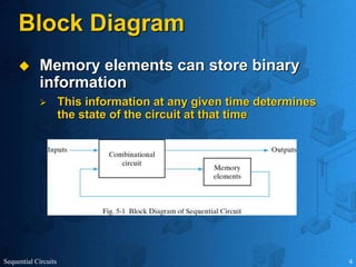
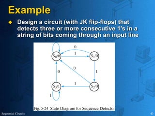
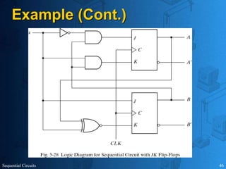
This document provides an overview of sequential circuits. It defines sequential circuits as circuits whose outputs depend on current and past input values, unlike combinational circuits whose outputs only depend on current inputs. It describes the main types of sequential circuits as synchronous (controlled by a clock) and asynchronous. Common memory elements for sequential circuits called flip-flops are introduced, including SR, D, J-K, and T flip-flops. The use of state tables and state diagrams to analyze sequential circuits is covered. Procedures for reducing states, assigning binary codes to states, and designing sequential circuits using flip-flops are also outlined. An example of designing a circuit to detect three or more consecutive 1s in an input bit string
Latches
– Flip-Flops - SR, JK, D and T
– Master Slave Flip Flops
• Shift Registers
– SISO, SIPO, PISO, PIPO and Universal
• Binary Counters
– Synchronous and asynchronous up/down counters
– mod - N counter
– Counters for random sequence
– Johnson counter and Ring counter
Design of Synchronous Sequential Circuits - State
Table and State Diagram - Design of Mealy and
Moore FSM
• Overlapping & Non-overlapping Sequence
detector
• Hazards - Hazard free realization - Case study on
Vending Machine FSM.
Introduction to Sequential DevicesChapter 66.1 M.docxbagotjesusa
Introduction to Sequential Devices
Chapter 6
6.1 Models for Sequential CircuitsElevator example:
6.1.1 Block Diagram representation
Memory devices:
- Semiconductor Flip-Flops
- Magnetic devices
- Delay lines
- Mechanical relays
- Rotation switches
- Etc…
This circuit can be represented by the following equations:
Vector Notation:
- All the vectors are time dependant
- Vector y has the value y(tk) at time tk.
- Input signals xi and output signal zi may assume a variety of forms
6.1.2 State Tables and DiagramsThe state diagram is a graphical representation of a sequential circuit in which the states are represented by circles and state transition of the circuit are shown by arrows.
State table : all circuit input vectors are listed across the top, while all state vectors are listed down the left side. Entries in the table are the next state and the output.
In practice, the state diagrams and tables are usually labeled using symbols rather than vectors. For example consider a sequential circuit with two present state variables y1, and y2. Then y= [y1 , y2]Therefore the vector y can have any of the four possible values:
In general, if r represents the number of memory devices (number of states) in a circuit with Ns states then
Example: Consider the following sequential circuit with one input x, two state variables y1 and y2, and one output z.
The state diagram is:
Let assume that the circuit is initially in state A. now consider the application of the following input sequence to the circuit:
Hence the input sequence applied to the machine in state A cause the output sequence
Z=0100110111
And leaves the circuit in its final state C.
6.2 Memory Devices-Most memory elements are bistable electronic circuits, that is, they exist indefinitely in one of two possible states, 0 and 1. - Binary data are stored in a memory element by placing the element into the 0 state to store 0 and into the 1 state to store 1. - The output of the memory indicates the present state. - The input of the memory indicates the next state. - Each memory element has one or more excitation inputs, so called because they are used to “excite” or drive the circuit into the desired state.
Two memory element types
The Two memory element types most commonly used in switching circuits are latches and flip-flops.1- LATCHES
A latch is a memory element whose excitation input signals control the state of
the device
A set latch: the excitation input forces the output of the device to 1.
A Reset latch: the excitation inputs force the device output to 0.
A Set-Reset latch: a latch with both set and reset excitation signals.
Timing Diagram of SR LATCH
2- FLIP-FLOP:
A flip-flop differs from a latch in that it has a
control signal called clock. The clock signal
issues a command to the flip-flop, allowing it
to change states in accordance with its
excitation input signals.
- In both latches and flip-flops, the next s.
Digital circuits Electronics Digital circuits Electronics Digital circuits Electronics Digital circuits Electronics Digital circuits Electronics Digital circuits Electronics Digital circuits Electronics Digital circuits Electronics Digital circuits Electronics Digital circuits Electronics Digital circuits Electronics Digital circuits Electronics Digital circuits Electronics Digital circuits Electronics Digital circuits Electronics Digital circuits Electronics Digital circuits Electronics Digital circuits Electronics Digital circuits Electronics Digital circuits Electronics Digital circuits Electronics Digital circuits Electronics Digital circuits Electronics Digital circuits Electronics Digital circuits Electronics Digital circuits Electronics Digital circuits Electronics Digital circuits Electronics Digital circuits Electronics Digital circuits Electronics Digital circuits Electronics Digital circuits Electronics Digital circuits Electronics Digital circuits Electronics Digital circuits Electronics Digital circuits Electronics Digital circuits Electronics Digital circuits Electronics Digital circuits Electronics Digital circuits Electronics Digital circuits Electronics Digital circuits Electronics Digital circuits Electronics Digital circuits Electronics Digital circuits Electronics Digital circuits Electronics Digital circuits Electronics Digital circuits Electronics Digital circuits Electronics Digital circuits Electronics Digital circuits Electronics Digital circuits Electronics Digital circuits Electronics Digital circuits Electronics Digital circuits Electronics Digital circuits Electronics Digital circuits Electronics Digital circuits Electronics Digital circuits Electronics Digital circuits Electronics Digital circuits Electronics Digital circuits Electronics Digital circuits Electronics Digital circuits Electronics Digital circuits Electronics Digital circuits Electronics Digital circuits Electronics Digital circuits Electronics Digital circuits Electronics Digital circuits Electronics Digital circuits Electronics Digital circuits Electronics Digital circuits Electronics Digital circuits Electronics Digital circuits Electronics Digital circuits Electronics Digital circuits Electronics Digital circuits Electronics Digital circuits Electronics Digital circuits Electronics Digital circuits Electronics Digital circuits Electronics Digital circuits Electronics Digital circuits Electronics Digital circuits Electronics Digital circuits Electronics Digital circuits Electronics Digital circuits Electronics Digital circuits Electronics Digital circuits Electronics Digital circuits Electronics Digital circuits Electronics Digital circuits Electronics Digital circuits Electronics Digital circuits Electronics Digital circuits Electronics Digital circuits Electronics Digital circuits Electronics Digital circuits Electronics Digital circuits Electronics Digital circuits Electronics Digital circuits Electronics Digital circuits Electronics Digital circ
Can AI do good? at 'offtheCanvas' India HCI preludeAlan Dix
Invited talk at 'offtheCanvas' IndiaHCI prelude, 29th June 2024.
https://www.alandix.com/academic/talks/offtheCanvas-IndiaHCI2024/
The world is being changed fundamentally by AI and we are constantly faced with newspaper headlines about its harmful effects. However, there is also the potential to both ameliorate theses harms and use the new abilities of AI to transform society for the good. Can you make the difference?
Book Formatting: Quality Control Checks for DesignersConfidence Ago
This presentation was made to help designers who work in publishing houses or format books for printing ensure quality.
Quality control is vital to every industry. This is why every department in a company need create a method they use in ensuring quality. This, perhaps, will not only improve the quality of products and bring errors to the barest minimum, but take it to a near perfect finish.
It is beyond a moot point that a good book will somewhat be judged by its cover, but the content of the book remains king. No matter how beautiful the cover, if the quality of writing or presentation is off, that will be a reason for readers not to come back to the book or recommend it.
So, this presentation points designers to some important things that may be missed by an editor that they could eventually discover and call the attention of the editor.
Transforming Brand Perception and Boosting Profitabilityaaryangarg12
In today's digital era, the dynamics of brand perception, consumer behavior, and profitability have been profoundly reshaped by the synergy of branding, social media, and website design. This research paper investigates the transformative power of these elements in influencing how individuals perceive brands and products and how this transformation can be harnessed to drive sales and profitability for businesses.
Through an exploration of brand psychology and consumer behavior, this study sheds light on the intricate ways in which effective branding strategies, strategic social media engagement, and user-centric website design contribute to altering consumers' perceptions. We delve into the principles that underlie successful brand transformations, examining how visual identity, messaging, and storytelling can captivate and resonate with target audiences.
Methodologically, this research employs a comprehensive approach, combining qualitative and quantitative analyses. Real-world case studies illustrate the impact of branding, social media campaigns, and website redesigns on consumer perception, sales figures, and profitability. We assess the various metrics, including brand awareness, customer engagement, conversion rates, and revenue growth, to measure the effectiveness of these strategies.
The results underscore the pivotal role of cohesive branding, social media influence, and website usability in shaping positive brand perceptions, influencing consumer decisions, and ultimately bolstering sales and profitability. This paper provides actionable insights and strategic recommendations for businesses seeking to leverage branding, social media, and website design as potent tools to enhance their market position and financial success.
Between Filth and Fortune- Urban Cattle Foraging Realities by Devi S Nair, An...Mansi Shah
This study examines cattle rearing in urban and rural settings, focusing on milk production and consumption. By exploring a case in Ahmedabad, it highlights the challenges and processes in dairy farming across different environments, emphasising the need for sustainable practices and the essential role of milk in daily consumption.
Hello everyone! I am thrilled to present my latest portfolio on LinkedIn, marking the culmination of my architectural journey thus far. Over the span of five years, I've been fortunate to acquire a wealth of knowledge under the guidance of esteemed professors and industry mentors. From rigorous academic pursuits to practical engagements, each experience has contributed to my growth and refinement as an architecture student. This portfolio not only showcases my projects but also underscores my attention to detail and to innovative architecture as a profession.
3. Sequential Circuits 3
Sequential Circuits
Combinational
The outputs depend only on the current input
values
It uses only logic gates
Sequential
The outputs depend on the current and past input
values
It uses logic gates and storage elements
Example
Vending machine
They are referred as finite state machines since
they have a finite number of states
4. Sequential Circuits 4
Block Diagram
Memory elements can store binary
information
This information at any given time determines
the state of the circuit at that time
5. Sequential Circuits 5
Sequential Circuit Types
Synchronous
The circuit behavior is determined by the signals
at discrete instants of time
The memory elements are affected only at
discrete instants of time
A clock is used for synchronization
Memory elements are affected only with the
arrival of a clock pulse
If memory elements use clock pulses in their
inputs, the circuit is called
Clocked sequential circuit
6. Sequential Circuits 6
Sequential Circuit Types
ASynchronous
The circuit behavior is determined by the signals
at any instant of time
It is also affected by the order the inputs change
7. Sequential Circuits 7
Clock
It emits a series of pulses with a
precise pulse width and precise
interval between consecutive pulses
Timing interval between the
corresponding edges of two
consecutive pulses is known as the
clock cycle time, or period
9. Sequential Circuits 9
Flip-Flops
Can keep a binary state until an input
signal to switch the state is received
There are different types of flip-flops
depending on the number of inputs
and how the inputs affect the binary
state
10. Sequential Circuits 10
Latches
The most basic flip-flops
They operate with signal levels
The flip-flops are constructed from
latches
They are not useful for synchronous
sequential circuits
They are useful for asynchronous
sequential circuits
12. Sequential Circuits 12
SR Latch with NOR
1
R
1,
S
avoid
,
conditions
normal
In
0
set to
are
Q'
and
Q
undefined,
1
R
1,
S
state
reset
1
'
,
0
state
set
0
'
,
1
Q
Q
Q
Q
reset
R
set
S
14. Sequential Circuits 14
SR Latch with NAND
0
R
0,
S
avoid
,
conditions
normal
In
1
set to
are
Q'
and
Q
undefined,
0
R
0,
S
state
reset
0
'
,
1
state
set
1
'
,
0
Q
Q
Q
Q
reset
R
set
S
18. Sequential Circuits 18
Note
The control input changes the state of
a latch or flip-flop
The momentary change is called a
trigger
Example: D Latch
It is triggered every time the pulse goes to the
logic level 1
As long as the pulse remains at the logic level 1,
the change in the data (D) directly affects the
output (Q)
THIS MAY BE A BIG PROBLEM since the state of
the latch may keep changing depending on the
input (may be coming from a combinational logic
network)
26. Sequential Circuits 26
Direct Inputs
You can use asynchronous inputs to
put a flip-flop to a specific state
regardless of the clock
You can clear the content of a flip-flop
The content is changed to zero (0)
This is called clear or direct reset
This is particularly useful when the power is off
The state of the flip-flop is set to unknown
28. Sequential Circuits 28
State Equations
'
)
(
'
)
1
(
)
1
(
)
(
'
)
(
)
(
)
(
)
(
)
(
'
)
1
(
)
(
)
(
)
(
)
(
)
1
(
x
B
A
y
x
A
t
B
Bx
Ax
t
A
t
x
t
B
t
A
t
y
t
x
t
A
t
B
t
x
t
B
t
x
t
A
t
A
A state equation shows
the next state as a
function of the current
state and inputs
32. Sequential Circuits 32
State Reduction
Reduce the number of states but keep
the input-output requirements
Reducing the number of states may
reduce the number of flip-flops
If there are n flip-flops, there are 2^n states
If you have two circuits that produce
the same output sequence for any
given input sequence, the two circuits
are equivalent
They may replace each other
33. Sequential Circuits 33
State Reduction Example
Find the states for which the
next states and outputs are
the same
36. Sequential Circuits 36
State Assignment
You need to assign binary values for
each state so that they can be
implemented
You need to use enough number of
bits to cover all the states
38. Sequential Circuits 38
Design Procedure
Derive a state diagram
Reduce the number of states
Assign binary values to the states
Obtain binary coded state table
Choose the type of flip-flop to be used
Derive simplified flip-flop input
equations and output equations
Draw the logic diagram
39. Sequential Circuits 39
Example
Design a circuit (with D flip-flops) that
detects three or more consecutive 1’s in a
string of bits coming through an input line
40. Sequential Circuits 40
Example (Cont.)
7
,
6
)
,
,
(
7
,
5
,
1
)
,
,
(
)
1
(
7
,
5
,
3
)
,
,
(
)
1
(
x
B
A
y
x
B
A
D
t
B
x
B
A
D
t
A
B
A
43. Sequential Circuits 43
Example
Design a circuit (with JK flip-flops) that
detects three or more consecutive 1’s in a
string of bits coming through an input line