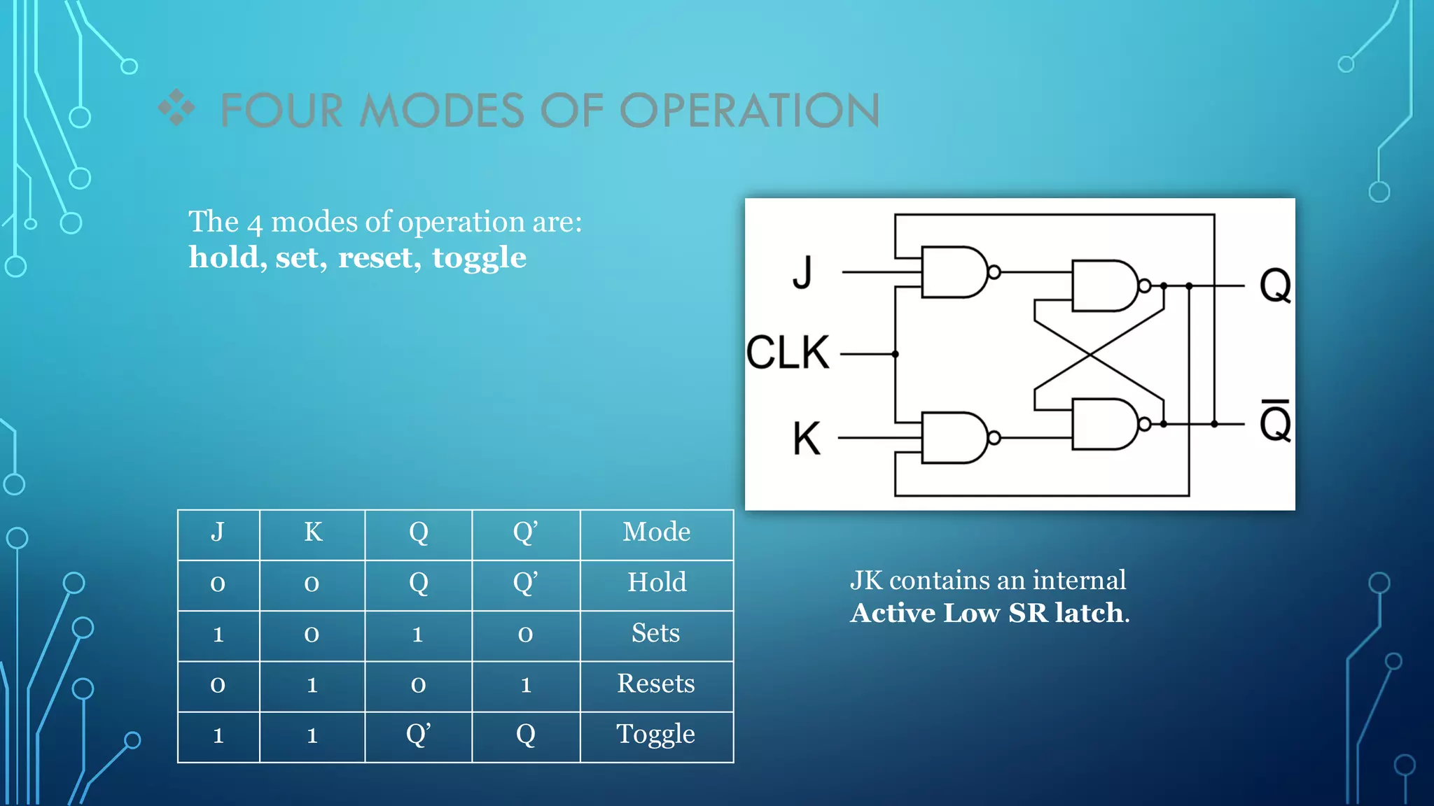
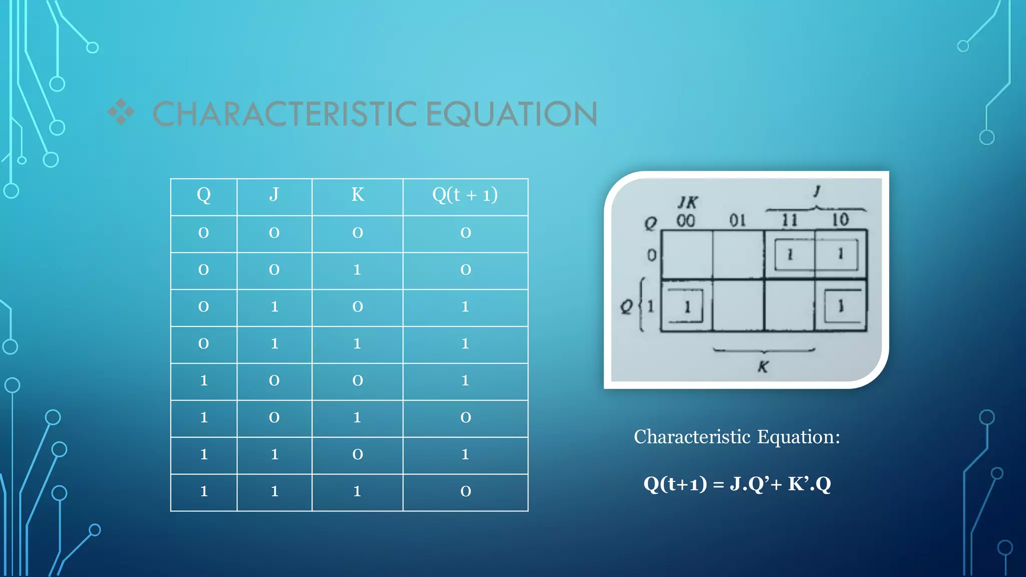
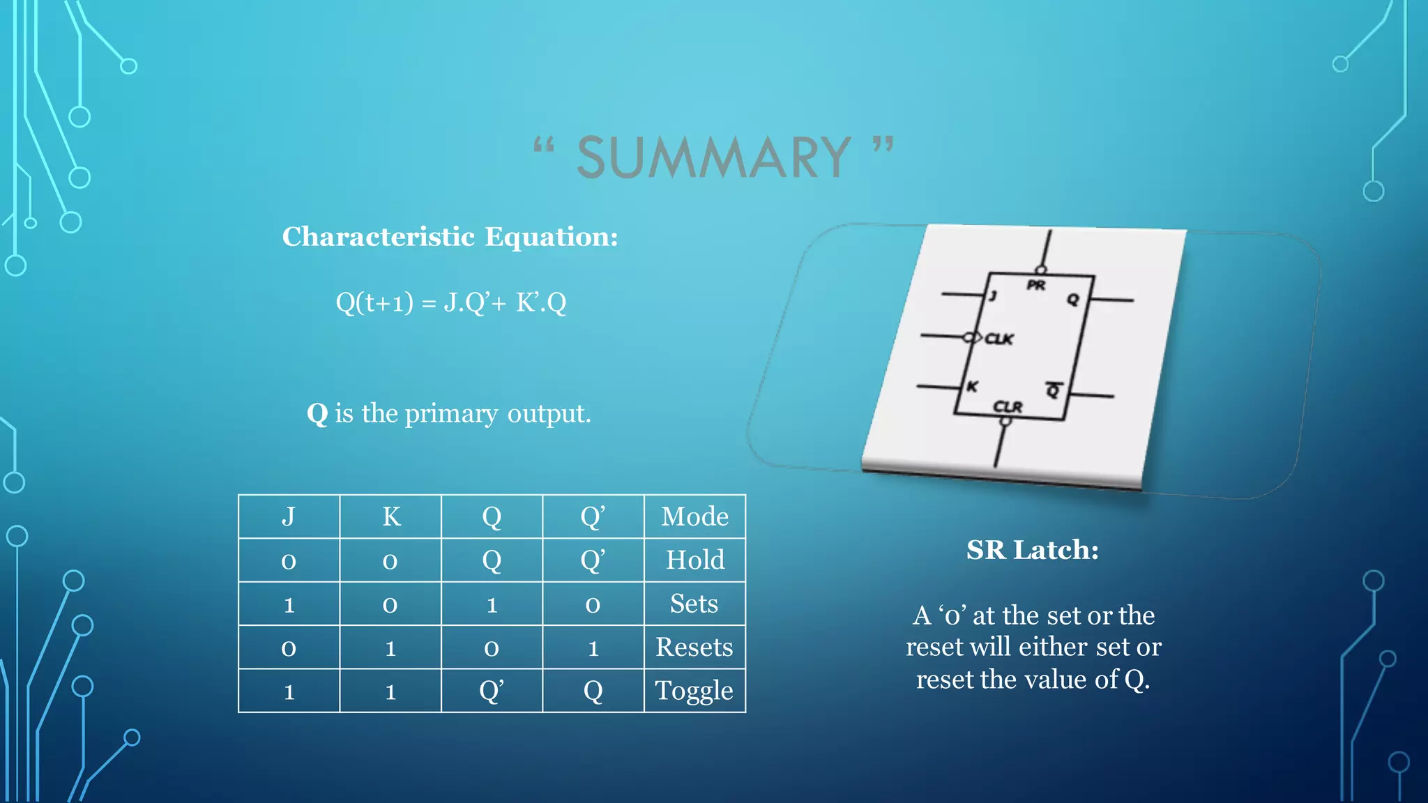
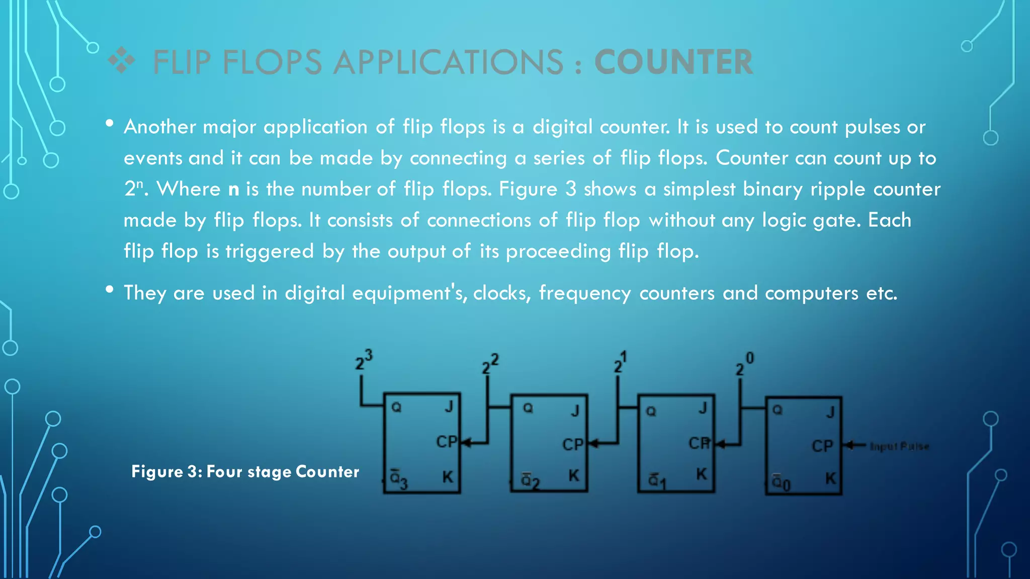
JK flip-flops have two outputs, Q and Q', and four modes of operation: hold, set, reset, toggle. The primary output is Q. There are two stable states that can store state information. JK flip-flops are used for data storage in registers, counting in counters, and frequency division. They can divide the frequency of a periodic waveform in half by toggling on each input clock pulse.
The document explains about the concepts of sequential circuits in Digital electronics.
This will be helpful for the beginners in VLSI and electronics students.
JK flip flop in Digital electronics
You can watch my lectures at:
Digital electronics playlist in my youtube channel:
https://www.youtube.com/channel/UC_fItK7wBO6zdWHVPIYV8dQ?view_as=subscriber
My Website : https://easyninspire.blogspot.com/
This Presentation is useful to study Digital Electronics subject about D and T Flip-Flop. This Presentation is also useful to make Presentation on Flip-Flop.
1.Introduction
The 555 IC was designed in 1971 by Hans Camenzind under contract to SigNetics Corporation.
555 timer is a highly stable circuit used to generate time delays, or Oscillations.
A single 555 timer can provide time delay ranging from microseconds to hours.
It operates from a wide range of power supplies ranging from + 5 Volts to + 18 Volts supply voltage.
2.Pin Configuration
3.Working of Pin
4.555 Integral circuit
5.Operating modes of IC
6. Bistable Mode
In bistable (also called Schmitt trigger) mode, the 555 timer acts as a basic flip-flop.
The trigger and reset inputs (pins 2 and 4 respectively on a 555) are held high via pull-up resistors while the threshold input (pin 6) is simply floating.
Thus configured, pulling the trigger momentarily to ground acts as a 'set' and transitions the output pin (pin 3) to Vcc (high state).
Pulling the reset input to ground acts as a 'reset' and transitions the output pin to ground (low state). No timing capacitors
Pin 5 (control voltage) is connected to ground via a small-value capacitor (usually 0.01 to 0.1 μF). Pin 7 (discharge) is left floating
7.Monostable Mode
Pulse generator circuit which the period is calculated from RC network and connected to external of 555 timer
Stable when the output logic LOW (logic = 0)
When a pulse is trigger at pin 2 (normally negative trigger pulse), timer output will change to HIGH (+Vs) for a while and change to LOW (stable condition). The condition will continue LOW until pulse is trigger again.
The timing period is triggered (started) when trigger input (555 pin 2) is less than 1/3 Vs, this makes the output high (+Vs) and the capacitor C1 starts to charge through resistor R1. Once the time period has started further trigger pulses are ignored.
The threshold input (555 pin 6) monitors the voltage across C1 and when this reaches 2/3 Vs the time period over and the output becomes LOW,
At the same time discharge (555 pin 7) is connected to 0V, discharging the capacitor ready for the next trigger.
8.Astable Mode
Astable multivibrators are also known as Free-running Multivibrator.
Astable do not need trigger pulse for external to change the output.
The period for LOW and HIGH can be calculated based on resistor and capacitor value that connected at outside of timer.
9.Applications
Schmitt trigger
PPM
PWM
Linear Ramp generator
Precision Timing
Pulse Generation
Time Delay Generation
Sequential Timing
Used as a quad timer
10. Conclusion
Hence 555 IC timer can produce very accurate and stable time delays, from microseconds to hours. It can be used with supply voltage varying from 5 to 18 V. Timer can be used in monostable mode of operation or astable mode of operation. Its various applications include waveform generator, missing pulse detector, frequency divider, pulse width modulator, burglar alarm, FSK generator, ramp generator, pulse position modulator etc.
flip flop,introduction,types,. SR Flip Flop
a.SR Flip Flop Active Low = NAND gate Latch
b. SR Flip Flop Active High = NOR gate Latch
2. Clocked SR Flip Flop
3. JK Flip Flop
4. JK Flip Flop With Pre-set And Clear
5. T Flip Flop
6. D Flip Flop
7. Master-Slave Edge-Triggered Flip-Flop
The Used of Flip Flop:
ppt on flip flops
contents :
Made by : Dhanesh RK Nair
WHAT IS FLIP FLOP?
In digital circuits, the flip-flop, is a kind of bistable multivibrator.
It is a Sequential Circuits / an electronic circuit which has two stable states and thereby is capable of serving as one bit of memory , bit 1 or bit 0.
TYPES OF FLIP FLOPS:
1. SR Flip Flop
2. Clocked SR Flip Flop
3. JK Flip Flop
4. JK Flip Flop With Preset And Clear
5. T Flip Flop
6. D Flip Flop
USES OF FLIP FLOPS:
For Memory circuits
For Logic Control Devices
For Counter Devices
For Register Devices
SR FLIP FLOP
The most basic Flip Flop is called SR Flip Flop.
The basic RS flip flop is an asynchronous device.
In asynchronous device, the outputs is immediately changed anytime one or more of the inputs change just as in combinational logic circuits.
It does not operate in step with a clock or timing.
CLOCKED SR FLIP FLOP
Additional clock input is added to change the SR flipflop from an element used in asynchronous sequential circuits to one, which can be used in synchronous circuits.
The clocked SR flip flop logic symbol that is triggered by the PGT
Its means that the flip flop can change the output states only when clock signal makes a transition from LOW to HIGH.
JK FLIP FLOP
Another types of Flip flop is JK flip flop.
It differs from the RS flip flops when J=K=1 condition is not indeterminate but it is defined to give a very useful changeover (toggle) action.
Toggle means that Q and Q(compliment) will switch to their opposite states.
The JK Flip flop has clock input Cp and two control inputs J and K.
Operation of Jk Flip Flop is completely described by truth table
T FLIP FLOP
The T flip flop has only the Toggle and Hold Operation.
If Toggle mode operation. The output will toggle from 1 to 0 or vice versa.
D FLIP FLOP
Also Known as Data Flip flop
Can be constructed from RS Flip Flop or JK Flip flop by addition of an inverter.
Inverter is connected so that the R input is always the inverse of S (or J input is always complementary of K).
The D flip flop will act as a storage element for a single binary digit (Bit).
THANKS....!!!!
SOME MORE CONTENTS :
In electronics, a flip-flop or latch is a circuit that has two stable states and can be used to store state information. A flip-flop is a bistable multivibrator. The circuit can be made to change state by signals applied to one or more control inputs and will have one or two outputs. It is the basic storage element in sequential logic. Flip-flops and latches are fundamental building blocks of digital electronics systems used in computers, communications, and many other types of systems.
Flip-flops and latches are used as data storage elements. A flip-flop stores a single bit (binary digit) of data; one of its two states represents a "one" and the other represents a "zero". Such data storage can be used for storage of state, and such a circuit is described as sequential logic.
THANKS!!!!!!!!!!!
Flipflops JK T SR D All FlipFlop SlidesSid Rehmani
Flipflops JK T SR D All FlipFlop Slides. Uploaded by SidRehmani.
Jk flip flop presentation, T flip flop presentation, D flip flop presentation, D flip flop presentation.
Follow Me For More:
facebook.com/RjSidRehmani
Definition, Composition of atmospheric air, Classification and sources of air
pollutants. Effects of air pollution on human, plant and material, Air pollution control methods, equipment and safety.
About
Indigenized remote control interface card suitable for MAFI system CCR equipment. Compatible for IDM8000 CCR. Backplane mounted serial and TCP/Ethernet communication module for CCR remote access. IDM 8000 CCR remote control on serial and TCP protocol.
• Remote control: Parallel or serial interface.
• Compatible with MAFI CCR system.
• Compatible with IDM8000 CCR.
• Compatible with Backplane mount serial communication.
• Compatible with commercial and Defence aviation CCR system.
• Remote control system for accessing CCR and allied system over serial or TCP.
• Indigenized local Support/presence in India.
• Easy in configuration using DIP switches.
Technical Specifications
Indigenized remote control interface card suitable for MAFI system CCR equipment. Compatible for IDM8000 CCR. Backplane mounted serial and TCP/Ethernet communication module for CCR remote access. IDM 8000 CCR remote control on serial and TCP protocol.
Key Features
Indigenized remote control interface card suitable for MAFI system CCR equipment. Compatible for IDM8000 CCR. Backplane mounted serial and TCP/Ethernet communication module for CCR remote access. IDM 8000 CCR remote control on serial and TCP protocol.
• Remote control: Parallel or serial interface
• Compatible with MAFI CCR system
• Copatiable with IDM8000 CCR
• Compatible with Backplane mount serial communication.
• Compatible with commercial and Defence aviation CCR system.
• Remote control system for accessing CCR and allied system over serial or TCP.
• Indigenized local Support/presence in India.
Application
• Remote control: Parallel or serial interface.
• Compatible with MAFI CCR system.
• Compatible with IDM8000 CCR.
• Compatible with Backplane mount serial communication.
• Compatible with commercial and Defence aviation CCR system.
• Remote control system for accessing CCR and allied system over serial or TCP.
• Indigenized local Support/presence in India.
• Easy in configuration using DIP switches.
Hybrid optimization of pumped hydro system and solar- Engr. Abdul-Azeez.pdffxintegritypublishin
Advancements in technology unveil a myriad of electrical and electronic breakthroughs geared towards efficiently harnessing limited resources to meet human energy demands. The optimization of hybrid solar PV panels and pumped hydro energy supply systems plays a pivotal role in utilizing natural resources effectively. This initiative not only benefits humanity but also fosters environmental sustainability. The study investigated the design optimization of these hybrid systems, focusing on understanding solar radiation patterns, identifying geographical influences on solar radiation, formulating a mathematical model for system optimization, and determining the optimal configuration of PV panels and pumped hydro storage. Through a comparative analysis approach and eight weeks of data collection, the study addressed key research questions related to solar radiation patterns and optimal system design. The findings highlighted regions with heightened solar radiation levels, showcasing substantial potential for power generation and emphasizing the system's efficiency. Optimizing system design significantly boosted power generation, promoted renewable energy utilization, and enhanced energy storage capacity. The study underscored the benefits of optimizing hybrid solar PV panels and pumped hydro energy supply systems for sustainable energy usage. Optimizing the design of solar PV panels and pumped hydro energy supply systems as examined across diverse climatic conditions in a developing country, not only enhances power generation but also improves the integration of renewable energy sources and boosts energy storage capacities, particularly beneficial for less economically prosperous regions. Additionally, the study provides valuable insights for advancing energy research in economically viable areas. Recommendations included conducting site-specific assessments, utilizing advanced modeling tools, implementing regular maintenance protocols, and enhancing communication among system components.
NO1 Uk best vashikaran specialist in delhi vashikaran baba near me online vas...Amil Baba Dawood bangali
Contact with Dawood Bhai Just call on +92322-6382012 and we'll help you. We'll solve all your problems within 12 to 24 hours and with 101% guarantee and with astrology systematic. If you want to take any personal or professional advice then also you can call us on +92322-6382012 , ONLINE LOVE PROBLEM & Other all types of Daily Life Problem's.Then CALL or WHATSAPP us on +92322-6382012 and Get all these problems solutions here by Amil Baba DAWOOD BANGALI
#vashikaranspecialist #astrologer #palmistry #amliyaat #taweez #manpasandshadi #horoscope #spiritual #lovelife #lovespell #marriagespell#aamilbabainpakistan #amilbabainkarachi #powerfullblackmagicspell #kalajadumantarspecialist #realamilbaba #AmilbabainPakistan #astrologerincanada #astrologerindubai #lovespellsmaster #kalajaduspecialist #lovespellsthatwork #aamilbabainlahore#blackmagicformarriage #aamilbaba #kalajadu #kalailam #taweez #wazifaexpert #jadumantar #vashikaranspecialist #astrologer #palmistry #amliyaat #taweez #manpasandshadi #horoscope #spiritual #lovelife #lovespell #marriagespell#aamilbabainpakistan #amilbabainkarachi #powerfullblackmagicspell #kalajadumantarspecialist #realamilbaba #AmilbabainPakistan #astrologerincanada #astrologerindubai #lovespellsmaster #kalajaduspecialist #lovespellsthatwork #aamilbabainlahore #blackmagicforlove #blackmagicformarriage #aamilbaba #kalajadu #kalailam #taweez #wazifaexpert #jadumantar #vashikaranspecialist #astrologer #palmistry #amliyaat #taweez #manpasandshadi #horoscope #spiritual #lovelife #lovespell #marriagespell#aamilbabainpakistan #amilbabainkarachi #powerfullblackmagicspell #kalajadumantarspecialist #realamilbaba #AmilbabainPakistan #astrologerincanada #astrologerindubai #lovespellsmaster #kalajaduspecialist #lovespellsthatwork #aamilbabainlahore #Amilbabainuk #amilbabainspain #amilbabaindubai #Amilbabainnorway #amilbabainkrachi #amilbabainlahore #amilbabaingujranwalan #amilbabainislamabad
Saudi Arabia stands as a titan in the global energy landscape, renowned for its abundant oil and gas resources. It's the largest exporter of petroleum and holds some of the world's most significant reserves. Let's delve into the top 10 oil and gas projects shaping Saudi Arabia's energy future in 2024.
Vaccine management system project report documentation..pdfKamal Acharya
The Division of Vaccine and Immunization is facing increasing difficulty monitoring vaccines and other commodities distribution once they have been distributed from the national stores. With the introduction of new vaccines, more challenges have been anticipated with this additions posing serious threat to the already over strained vaccine supply chain system in Kenya.
Forklift Classes Overview by Intella PartsIntella Parts
Discover the different forklift classes and their specific applications. Learn how to choose the right forklift for your needs to ensure safety, efficiency, and compliance in your operations.
For more technical information, visit our website https://intellaparts.com
Final project report on grocery store management system..pdfKamal Acharya
In today’s fast-changing business environment, it’s extremely important to be able to respond to client needs in the most effective and timely manner. If your customers wish to see your business online and have instant access to your products or services.
Online Grocery Store is an e-commerce website, which retails various grocery products. This project allows viewing various products available enables registered users to purchase desired products instantly using Paytm, UPI payment processor (Instant Pay) and also can place order by using Cash on Delivery (Pay Later) option. This project provides an easy access to Administrators and Managers to view orders placed using Pay Later and Instant Pay options.
In order to develop an e-commerce website, a number of Technologies must be studied and understood. These include multi-tiered architecture, server and client-side scripting techniques, implementation technologies, programming language (such as PHP, HTML, CSS, JavaScript) and MySQL relational databases. This is a project with the objective to develop a basic website where a consumer is provided with a shopping cart website and also to know about the technologies used to develop such a website.
This document will discuss each of the underlying technologies to create and implement an e- commerce website.
Explore the innovative world of trenchless pipe repair with our comprehensive guide, "The Benefits and Techniques of Trenchless Pipe Repair." This document delves into the modern methods of repairing underground pipes without the need for extensive excavation, highlighting the numerous advantages and the latest techniques used in the industry.
Learn about the cost savings, reduced environmental impact, and minimal disruption associated with trenchless technology. Discover detailed explanations of popular techniques such as pipe bursting, cured-in-place pipe (CIPP) lining, and directional drilling. Understand how these methods can be applied to various types of infrastructure, from residential plumbing to large-scale municipal systems.
Ideal for homeowners, contractors, engineers, and anyone interested in modern plumbing solutions, this guide provides valuable insights into why trenchless pipe repair is becoming the preferred choice for pipe rehabilitation. Stay informed about the latest advancements and best practices in the field.
Student information management system project report ii.pdfKamal Acharya
Our project explains about the student management. This project mainly explains the various actions related to student details. This project shows some ease in adding, editing and deleting the student details. It also provides a less time consuming process for viewing, adding, editing and deleting the marks of the students.
2. v OUTLINE
• JK flip-flops definition
• Outputs
• Inputs
• Mode of operation
• Some Applications of the “JK Flip-Flops” : - Data storage.
- Counter.
- Frequency division.
3. v WHAT IS A JK FLIP-FLOP ?
• A flip-flop is a circuit that has two stable states and can be used
to store state information.
• The flip-flop can be made to change state by signals applied to
one or more control inputs and will have one or two outputs.
4. v JK STRUCTURE
JK Has 5 inputs named:
J(set),K(reset), PR, CLR, and CLK
JK Has 2 outputs: Q and Q’
Set: when it stores a binary 1
Cleared (reset): when it stores a binary 0
PR = Preset
CLR = Clear
CLK = Clock
5. v OUTPUTS
The Q output is the primary
output. This means that the binary
bit stored in the flip-flop, 1 or 0, is
the same as Q.
The Q’ output is the
opposite binary bit value
that is stored in Q.
The PR and CLR inputs
always override the J,K
inputs.
6. v INPUTS: PR AND CLR
A low at the PR input sets Q = 1
A low at the CLR input sets Q = 0
7. v INPUTS : J AND K
— The logic states applied to the J and K inputs cause the flip-
flop to operate 4 different ways.
— The way the logic state is applied to J and K is called Mode
of Operation.
— The mode of operation refers to the condition of the flip-flop
as it prepares for the positive clock pulse.
8. v FOUR MODES OF OPERATION
J K Q Q’ Mode
0 0 Q Q’ Hold
1 0 1 0 Sets
0 1 0 1 Resets
1 1 Q’ Q Toggle
The 4 modes of operation are:
hold, set, reset, toggle
JK contains an internal
Active Low SR latch.
9. v ACTIVE LOW SR LATCH
S’ – “set” R’ – “reset” Q Q’
0 0 Invalid Invalid
0 1 1 0
1 0 0 1
1 1 Q Q’
Point to remember:
A ‘0’ at the set or the reset will
either set or reset the value of
Q.
10. v TRUTH TABLE FOR NAND
A B X
0 0 1
0 1 1
1 0 1
1 1 0
A B C X
0 0 0 1
0 0 1 1
0 1 0 1
0 1 1 1
1 0 0 1
1 0 1 1
1 1 0 1
1 1 1 0
2 Inputs: 3 Inputs:
11. v MODE OF OPERATION: HOLD
J K Q Q’ Orig. Q Orig. Q’
0 0 0 1 0 1
Hold: no change in Q.
12. v MODE OF OPERATION: SET
J K Q Q’ Orig. Q Orig. Q’
1 0 1 0 0 1
Set: Q = 1.
13. v MODE OF OPERATION: RESET
J K Q Q’ Orig. Q Orig. Q’
0 1 0 1 1 0
Reset: Q = 0.
14. v MODE OF OPERATION: TOGGLE
J K Q Q’ Orig. Q Orig. Q’
1 1 1 0 0 1
Toggle: Q = Q’.
15. v MODE OF OPERATION: TOGGLE AGAIN
J K Q Q’ Orig. Q Orig. Q’
1 1 0 1 1 0
Toggle: Q = Q’.
18. “ SUMMARY ”
J K Q Q’ Mode
0 0 Q Q’ Hold
1 0 1 0 Sets
0 1 0 1 Resets
1 1 Q’ Q Toggle
Characteristic Equation:
Q(t+1) = J.Q’+ K’.Q
Q is the primary output.
SR Latch:
A ‘0’ at the set or the
reset will either set or
reset the value of Q.
19. v FLIP FLOPS APPLICATIONS : DATA STORAGE
• A flip flop store one bit at a time in digital circuit. In
order to store more than one bit flip flop can be
connected in series and parallel called registers. A
register is simply a data storage device for a number of
bits in which each flip flop store one bit of information
(0 or 1). Thus a 4 bit register consists of 4 individual flip
flops, each able to store one bit of information at a
time.
• Figure 1 shows a 4 bit register. Any number from
(0000)2 to (1111)2 may be stored in it simply by setting
or resetting the appropriate flip flops. Let us suppose
that flip flop one is SET(1) , Flip flop 2 is RESET(0), flip
flop 3 is RESET(0) and flip flop 4 is SET(1), the binary
number stored in this register is (1001)2.
Figure 1: Bit Binary Register
20. v FLIP FLOPS APPLICATIONS : COUNTER
• Another major application of flip flops is a digital counter. It is used to count pulses or
events and it can be made by connecting a series of flip flops. Counter can count up to
2n. Where n is the number of flip flops. Figure 3 shows a simplest binary ripple counter
made by flip flops. It consists of connections of flip flop without any logic gate. Each
flip flop is triggered by the output of its proceeding flip flop.
• They are used in digital equipment's, clocks, frequency counters and computers etc.
Figure 3: Four stage Counter
21. v FLIP FLOPS APPLICATIONS : FREQUENCY DIVIDER
• Flip flops can divide the frequency of periodic waveform. When a pulse wave is used to toggle an
flip flop, the output frequency becomes one half the input frequency, as shown in Figure 4
• The output of each flip flop is half the frequency of an input. If the input frequency is 160 KHz
then output of each flip flop would be so after first flip flop, 40 after second flip flop and 20
after third flip flop.
• Suppose that the Input frequency 160 KHz :
Frequency of first flip flop 80 KHz
Frequency of 2nd flips flop 40 KHz
Frequency of 3rd flips flop 20 KHz
Figure 4: JK Flip Flop Used as A Frequency Division