Downloaded 194 times
![Full Adder Circuit
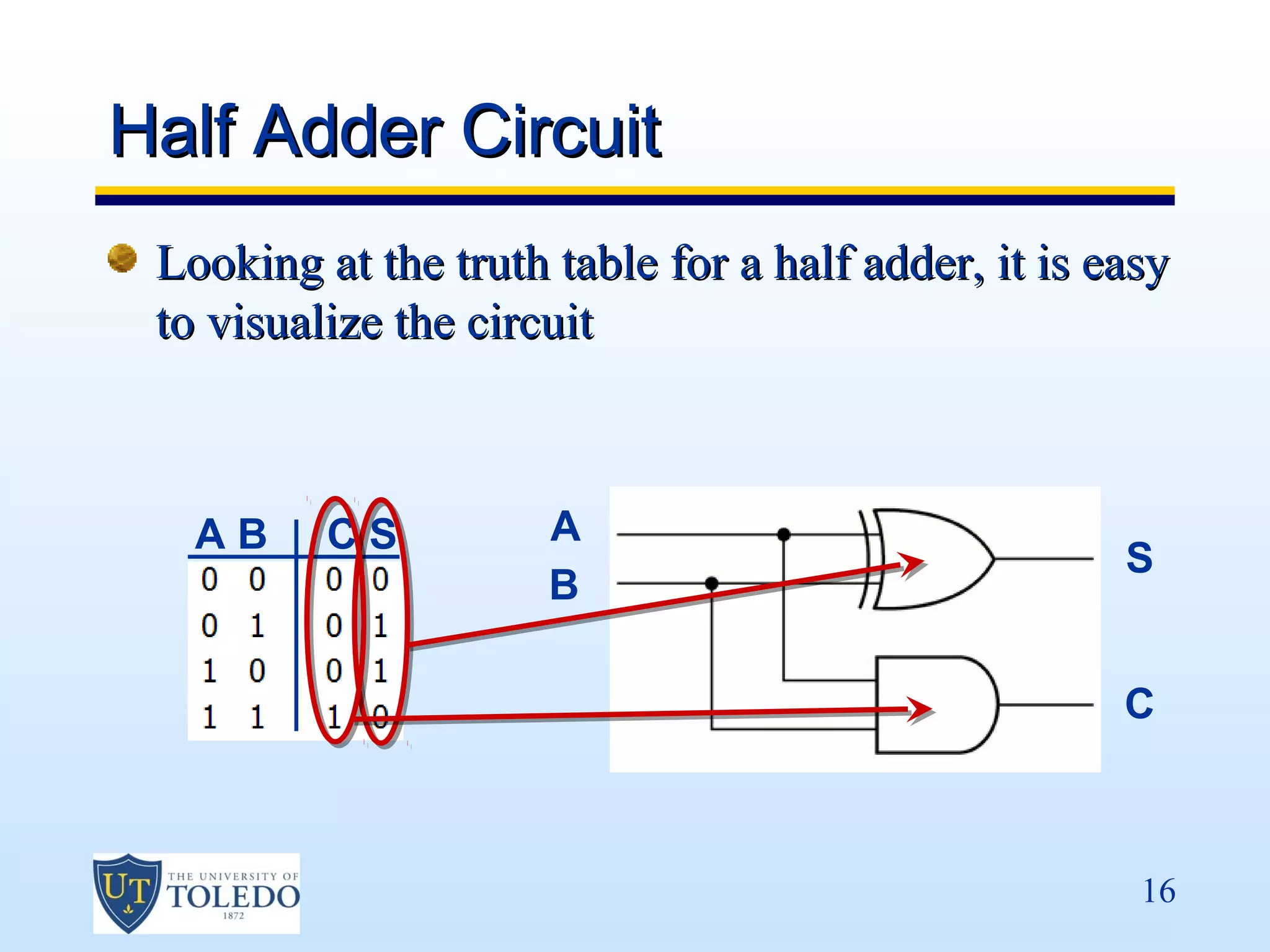
The circuit at right shows a half adder
full adder constructed from
two half adders.
XOR generates the sum
output
AND generates the carry
output half adder
[ ]
C = ( A ⋅ B + A ⋅ B ) ⋅ C ′ + ( A ⋅ B ) = ( A ⋅ B ⋅ C ′) + ( A ⋅ B ⋅ C ′) + ( A ⋅ B )
= ( A ⋅ C ′) + ( B ⋅ C ′) + ( A ⋅ B )
S = A ⊕ B ⊕ C′
17](https://image.slidesharecdn.com/lec13-130220045202-phpapp01/75/VHDL-Part-4-17-2048.jpg)

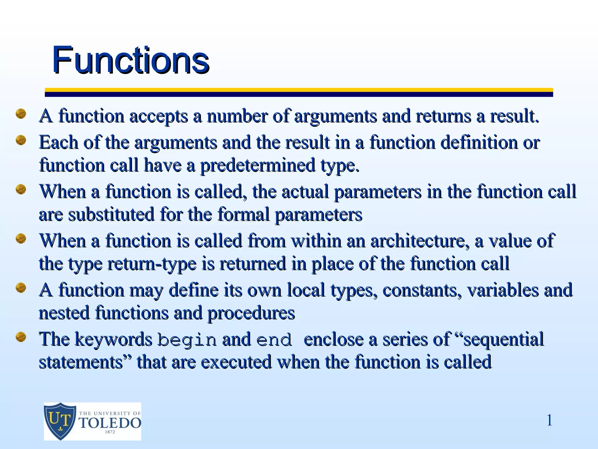
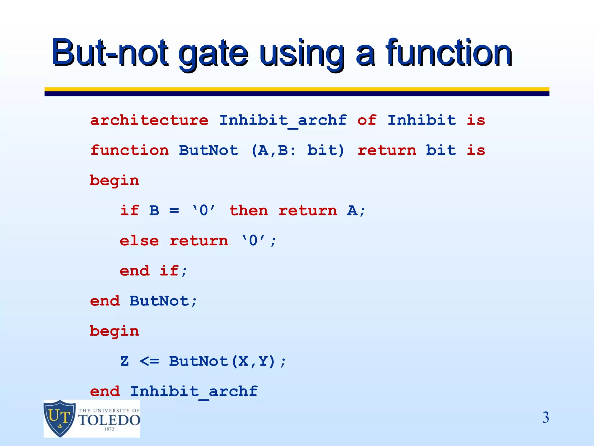
This document describes functions in VHDL. It states that a function accepts arguments and returns a result of a predetermined type. When called, actual parameters are substituted for formal parameters and the function call is replaced by the return type value. A function can define local types, constants, variables, nested functions and procedures. The keywords begin and end enclose sequential statements executed when the function is called. It then provides a simple example of an inhibit gate using a function.