Download as PDF, PPTX


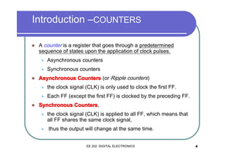


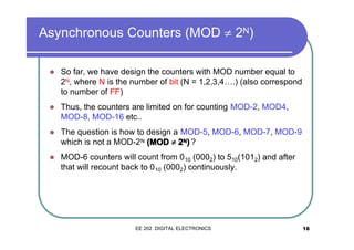
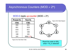


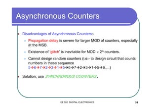

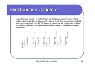

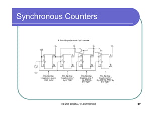


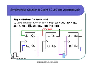


This document discusses synchronous and asynchronous counters. It begins by explaining the basic concepts of asynchronous and synchronous counters, noting the key difference that synchronous counters have all flip-flops share the same clock signal, so their outputs change simultaneously. The document then provides details on designing various types of counters, including synchronous up/down counters and higher modulus counters using cascading. It also discusses advantages of synchronous counters over asynchronous counters, such as not having propagation delays or being able to design random counting sequences.


![COUNTERS [Synchronous and Asynchronous]](https://cdn.slidesharecdn.com/ss_thumbnails/counters-211217083059-thumbnail.jpg?width=640&height=640&fit=bounds)


