Downloaded 1,531 times
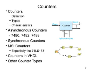
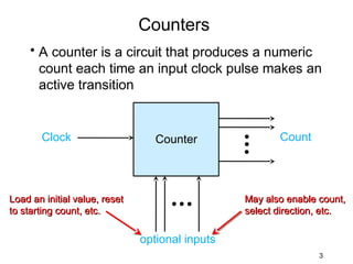
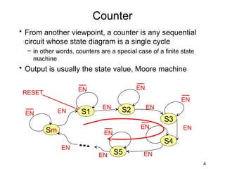
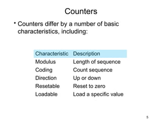
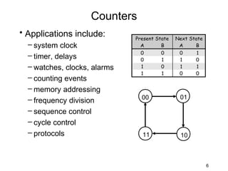

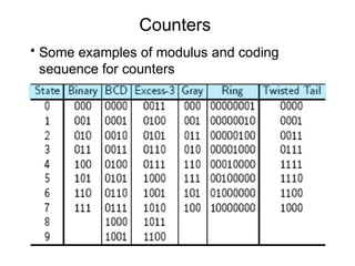
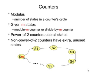
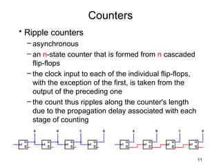
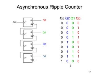
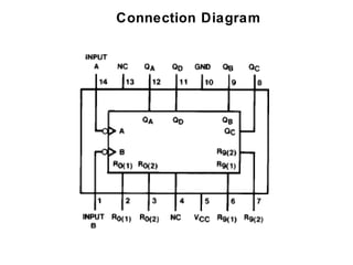
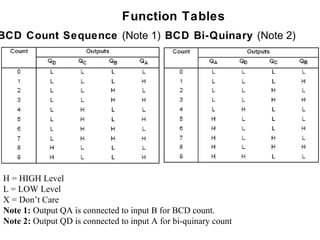
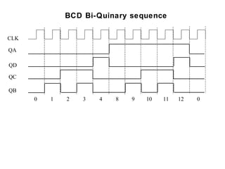
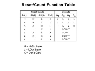
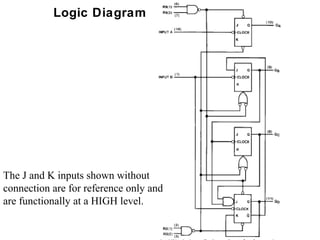
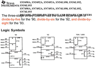
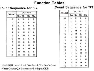
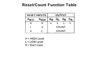
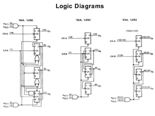
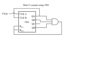
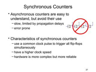
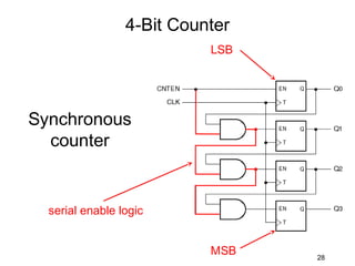
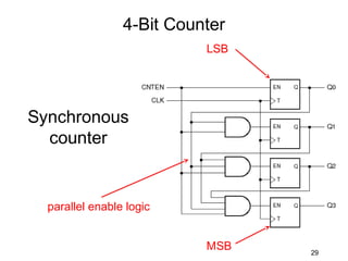
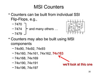
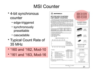
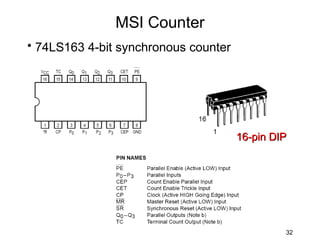
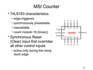
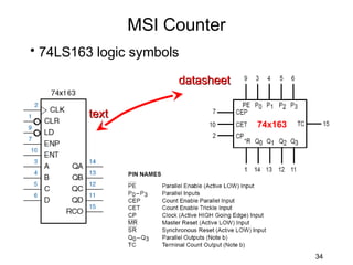
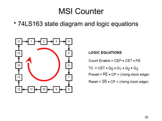
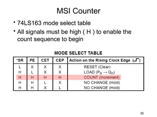
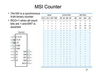
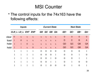
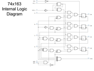

This document provides information about different types of counters, including asynchronous counters, synchronous counters, MSI counters, and specific counter integrated circuits. It defines counters and describes their basic characteristics. It discusses asynchronous ripple counters and their timing. It provides examples of decade and binary counters. It describes synchronous counters and MSI counters like the 74LS163 4-bit synchronous counter. Finally, it provides truth tables, logic diagrams, and application information for common counter ICs like the 7490, 7492, 7493, and 74LS163.