SlideShare a Scribd company logo
Analysis: Example 2 - New State Machine
  • This is now a Moore machine
    – output MAXS depends only on state (Q0 and Q1)

                                            MAXS


                                         MAXS = Q0 ⋅ Q1


                                                      1
Analysis: Example 2 - New Table/Diagram
  • Updated State/Output Table & Diagram
    – Moore machine state diagram


                  output associated with state, not transition
                                                                 2
Analysis: Example 2 - Timing Diagram
• Timing Diagram for State Machine
  – Compare outputs MAX and MAXS for the Mealy
    and Moore machine implementations


                                                 3
Conversion of Models
 • Mealy to Moore machine
     – If all the transitions in a Mealy model to a particular state are
       associated with the same output then in the corresponding
       Moore model that output becomes the state output.

T1                                      T1
       1/0                                      1

T2 1/0               1/0                T2 1         A      1       B
              A             B
                                                     0              0
                     0/1                                     0
       0/0                                      0
T3                         T4           T3                       T4
             Mealy                                  Moore
Conversion of Models
• Mealy to Moore machine
     – If the outputs of all the transitions in a Mealy model to a
       particular state are not the same, then in the corresponding
       Moore model we need to insert intermediate states

T1                                     T1                     T4
        1/0                                   1           0

T2 0/0                1/0              T2 0        A0              B
                                                          1
               A             B
                                                   0               0
                      0/1
        1/1
T3                          T4                     A1     1
                                       T3     1
              Mealy                                1      0
                                                  Moore        T4
Conversion of Models
• Moore to Mealy machine
     – If the state transition from two different states of the same
       input leads to common state then one state can be eliminated

T1                                     T1
         1                                    1/0

T2 0         A0            B           T2 0/0               1/0
                    1                               A             B
             0             0

                                              1/1
         1    A1    1                  T3
T3
              1

              Moore                                 Mealy
Conversion of Models
• Moore to Mealy machine
     – If the state transition from two different states of the same
       input does not lead to the same state, then state output
       becomes the output corresponding to each input transition of
       that state
T1                                      T1
         1                                    1/0

T2            A               B         T2 0/0              0/0
        0            0                              A             B
              0               0
         1           1                        1/0           1/1
                          C             T3
T3                                                                C
             Moore        1                         Mealy
Analysis: Example 3 - State Machine
X Y   Q0 Q1      J0 = X·Y'
                 K0 = X·Y' + Y·Q1
       Q0' Q1'
                                J0             Q0
                                       J   Q

                               K0      K   Q


                                      J1 = X·Q0 + Y
                                J1             Q1
                                       J   Q
                               K1
                                       K   Q
                                                                            Z
                                Clk


                   K1 = Y·Q0' + X·Y'·Q0               Z = X·Q0·Q1 + Q0'·Q1'·Y
1. Determine the excitation equations for the flip flop inputs

         J 0 = X ⋅Y ′                               J 1 = X ⋅ Q0 + Y
         K 0 = X ⋅ Y ′ + Y ⋅ Q1                     K1 = Y ⋅ Q0′ + X ⋅ Y ′ ⋅ Q0

    2. Substitute the excitation equations into the flip flop
       characteristic equations to obtain transition equations.
           Q0* = J 0 ⋅ Q0′ + K 0′Q 0
                                                    characteristic equations
           Q1* = J 1 ⋅ Q1′ + K1′Q1

                                             ′
Q 0* = ( X ⋅ Y ′) ⋅ Q0′ + ( X ⋅ Y ′ + Y ⋅ Q1) Q 0          transition equations
                                                        ′
Q1* = ( X ⋅ Q0 + Y ) ⋅ Q1′ + ( Y ⋅ Q0′ + X ⋅ Y ′ ⋅ Q 0 ) Q1
Simplifying the transition equations
    Q0* = ( X ⋅ Y ′) ⋅ Q0′ + ( X ⋅ Y ′ + Y ⋅ Q1) ′ Q 0

   Q 0* = ( X ⋅ Y ) ⋅ Q0 + ( ( X ⋅ Y ) + ( Y ⋅ Q1) ) ⋅ Q0

                           (                   )
   Q0* = X ⋅ Y ⋅ Q 0 + ( X ⋅ Y ) ⋅ ( Y ⋅ Q1) ⋅ Q0

                               (     )(
    Q0* = X ⋅ Y ⋅ Q0 + X + Y ⋅ Y + Q1 ⋅ Q0  ))
    Q0* = X ⋅ Y ⋅ Q0 + ( ( X + Y ) ⋅ (Y + Q1) ) ⋅ Q0

    Q0* = X ⋅ Y ⋅ Q0 + ( X ⋅ Y + X ⋅ Q1 + Y ⋅ Y + Y ⋅ Q1) ⋅ Q0

    Q 0* = X ⋅ Y ′ ⋅ Q 0′ + X ′ ⋅ Y ′ ⋅ Q0 + X ′ ⋅ Q0 ⋅ Q1′ + Y ⋅ Q0 ⋅ Q1′
Simplifying the transition equations
      Q1* = ( X ⋅ Q0 + Y ) ⋅ Q1′ + ( Y ⋅ Q0′ + X ⋅ Y ′ ⋅ Q 0 ) ′ Q1
                                   ((    ) (
     Q1* = ( X ⋅ Q0 + Y ) ⋅ Q1 + Y ⋅ Q0 + X ⋅ Y ⋅ Q0 ⋅ Q1 ))
     Q1* = X ⋅ Q0 ⋅ Q1 + Y ⋅ Q1 + ( Y ⋅ Q0 ) ⋅ ( X ⋅ Y ⋅ Q0 ) ) ⋅ Q1
                                    (         )(
   Q1* = X ⋅ Q0 ⋅ Q1 + Y ⋅ Q1 + Y + Q0 ⋅ X + Y + Q0 ⋅ Q1       )
                                    ((        )(
   Q1* = X ⋅ Q0 ⋅ Q1 + Y ⋅ Q1 + Y + Q0 ⋅ X + Y + Q0 ⋅ Q1       ))
                            (
 Q1* = XQ0Q1 + Y Q1 + X Y + Y Y + Y Q0 + X Q 0 + YQ0 + Q0Q0 ⋅ Q1       )
               Q1* = X ⋅ Q0 ⋅ Q1′ + Y ⋅ Q1′ + X ′ ⋅ Y ′ ⋅ Q1
               + Y ′ ⋅ Q 0′ ⋅ Q1 + X ′ ⋅ Q0 ⋅ Q1 + Y ⋅ Q0 ⋅ Q1
3. Determine the output equations.
       Z = X ⋅ Q0 ⋅ Q1 + Y ⋅ Q0′ ⋅ Q1′          output equation
4. Use transition equations and output equations to construct
   transition/output table.
                        Transition/output table
          State                   Input XY

          Q1Q0     00        01        10         11

          00       00,0      10,1      01,0       10,1

          01       01,0      11,0      10,0       11,0

          10       10,0      00,0      11,0       00,0

          11       11,0      10,0      00,1       10,1

                          Next State Q1*Q0*, Z
6. Name the states and substitute state names for state –
    variable combinations in the transition/output table to obtain
    the state/output table.
                                   State/output table
Substituting the
state names as ‘A’    State                   Input XY
for Q1Q0 = 00,
‘B’ for Q1Q0 = 01,    S        00       01        10       11
‘C’ for Q1Q0 = 10,
‘D’ for Q1Q0 = 11.    A        A,0      C,1       B,0      C,1
S is current state
& S* is next state.   B        B,0      D,0       C,0      D,0

                      C        C,0      A,0       D,0      A,0

                      D        D,0      C,0       A,1      C,1

                                     Next State S*, Z
State diagram


                            10/0
00/0          A                              B          00/0
                  01,11/1          01,11/0


       10/1                                      10/0
                            01,11/0

                             11/1
00/0          D                              C           00/0
                              01/0

                             10/0
Synchronous Design Process
1. Construct a state diagram and/or state/output
   table corresponding to the word description or
   specification
2. Minimize the number of states
3. Choose a set of state variables and assign
   state variable combinations to the named
   states
4. Obtain the transition/output table
5. Determine the number of flip-flops and select
   the type of flip-flop to be used (D is often the
   default)
6. Construct the excitation table
7. Derive excitation equations
8. Derive output equations                          15
Design a clocked synchronous state machine
which accepts two serial strings of digits of
arbitrary length, starting with LSB and
produces the sum and carry of the two bit
streams as its output. The input bit streams
could come from two shift registers clocked
simultaneously .
Assuming Mealy machine design
Let the inputs be X and Y

Let the outputs be S and C
Obtaining the state Diagram
  Assume initial condition to be SC = 00
  Let the state be represented by state A
  If XY = 00, then output SC = 00, Same
  state A
       = 01, then output SC = 10, goes to
  state B
XY/SC = 10, then output SC = 10, goes to
  state B            01,10/10
 00/00      A                    B
       = 11, then output SC = 01, goes to
  state C
       11/01


               C
Obtaining the state Diagram
  Assume machine has moved to state B
  If XY = 00, then output SC = 00, goes to
  state A
       = 01, then output SC = 10, same state
  B
       = 10, then output SC = 10, same state
XY/SC
  B
                      01,10/10
       = 11, then output SC = 01, goes to
 00/00      A                   B     01,10/10
  state C        00/00

       11/01       11/01


               C
Obtaining the state Diagram
  Assume machine has moved to state C
  If XY = 00, then output SC = 10, goes to
  state B
       = 01, then output SC = 01, same state
  C
       = 10, then output SC = 01, same state
XY/SC
  C
                      01,10/10
       = 11, then output SC = 11, goes to
 00/00      A                   B     01,10/10
  state D        00/00

           11/01         11/01

                       00/10     11/11
01,10/01           C                     D
Obtaining the state Diagram
  Assume machine has moved to state D
  If XY = 00, then output SC = 10, goes to
  state B
       = 01, then output SC = 01, goes to
  state C
XY/SC = 10, then output SC = 01, goes to
                      01,10/10
  state C                              01,10/10
 00/00      A                   B
                 00/00
       = 11, then output SC = 11, same state
  D               11/01
           11/01                           00/10

                       00/10   11/11               11/11
01,10/01           C                   D
                          01,10/01
Obtaining the state/output table
                    State/output table
       State                 Input XY

       S       00       01       10       11

       A       A,00     B,10     B,10     C,01

       B       A,00     B,10     B,10     C,01

       C       B,10     C,01     C,01     D,11

       D       B,10     C,01     C,01     D,11

                      Next State S*, SC
Equivalent States
Two states are equivalent if it is impossible to
distinguish them by observing only the current
and future outputs of the machine .

A pair of equivalent states can be replaced by a
single state.

Two states S1 and S2 are equivalent if two
conditions are true.
1. S1 and S2 must produce the same values at
the state machine output(s) for all input
combinations.
2. For each input combination S1 and S2 must
State Minimization

Equivalen             State/output table
t states State                 Input XY

          S      00       01       10       11

          A      A,00     B,10     B,10     C,01

          B      A,00     B,10     B,10     C,01

          C      B,10     C,01     C,01     D,11

          D      B,10     C,01     C,01     D,11

                        Next State S*, SC
Equivalent states
Minimized state/output table & state diagram
                State/output table
        State                     Input XY

        S           00       01       10         11

        A           A,00     A,10     A,10       D,01

        D           A,10     D,01     D,01       D,11


                           Next State S*, SC

00/00                                                   01/01
                             11/01
01/10                                                   10/01
                A                            D
10/10                                                   11/11
                             00/10

                         State diagram
Assigning state variable to obtain
transition/output table
               Transition/output table
         State                   Input XY

         Q       00       01         10     11

         0       0,00     0,10       0,10   1,01

         1       0,10     1,01       1,01   1,11


                        Next State Q*, SC

Encoding A = 0 and D = 1
Choosing D type flip flop
Constructing the excitation table

                 Excitation/output table
         State                 Input XY

         Q       00     01         10     11

         0       0,00   0,10       0,10   1,01

         1       0,10   1,01       1,01   1,11

                                D, SC
Transferring onto K-maps to derive excitation &
output equations     Excitation/output table
                        State                   Input XY

                        Q         00     01         10     11

                        0         0,00   0,10       0,10   1,01

                        1         0,10   1,01       1,01   1,11


 State   Input XY                               D, SC

 Q       00 01 11 10
                                D = X· Y + X · Q +Y · Q
 0       0    0     1       0
                                C = X· Y + X · Q +Y · Q
 1       0    1     1       1
Transferring onto K-maps to derive excitation &
output equations     Excitation/output table
                        State                   Input XY

                        Q       00       01         10     11

                        0       0,00     0,10       0,10   1,01

                        1       0,10     1,01       1,01   1,11


 State   Input XY                               D, SC

 Q       00 01 11 10            S = X ⋅Y ⋅ Q + X ⋅Y ⋅ Q
 0       0    1     0       1   + X ⋅Y ⋅ Q + X ⋅Y ⋅ Q
 1       1    0     1       0   S = X ⊕Y ⊕Q
Circuit (logic) diagram
D = X· Y + X · Q +Y · Q             excitation equation

  S = X ⊕ Y ⊕ Q C = X· Y + X · Q +Y · Qoutput equations


           X Y Q
                                              C

                                              S


                             D Q

                                Q

     Clk

More Related Content

What's hot

Analysis of state machines
Analysis of state machinesAnalysis of state machines
Analysis of state machines
Abhilash Nair
 
State Machine Design and Synthesis
State Machine Design and SynthesisState Machine Design and Synthesis
State Machine Design and Synthesis
Abhilash Nair
 
Designing Clocked Synchronous State Machine
Designing Clocked Synchronous State MachineDesigning Clocked Synchronous State Machine
Designing Clocked Synchronous State Machine
Abhilash Nair
 
Mealy state machine
Mealy state machineMealy state machine
Mealy state machineArif Siyal
 
Mealy moore machine model
Mealy moore machine modelMealy moore machine model
Mealy moore machine model
deepinderbedi
 
Finite State Machines
Finite State Machines Finite State Machines
Finite State Machines
Basel Mansour
 
Moore and mealy machines
Moore and mealy machinesMoore and mealy machines
Moore and mealy machines
AYESHA JAVED
 
lecture 1 content
lecture 1 contentlecture 1 content
lecture 1 content
Cleveland Community College
 
95414579 flip-flop
95414579 flip-flop95414579 flip-flop
95414579 flip-flopKyawthu Koko
 
Admissions in india 2015
Admissions in india 2015Admissions in india 2015
Admissions in india 2015
Edhole.com
 
Detecting Drug Effects in the Brain
Detecting Drug Effects in the BrainDetecting Drug Effects in the Brain
Detecting Drug Effects in the Brainhtstatistics
 
Chapter 3
Chapter 3Chapter 3
Chapter 3
EasyStudy3
 
Ppt tls
Ppt tlsPpt tls
X2 T07 05 conical pendulum
X2 T07 05 conical pendulumX2 T07 05 conical pendulum
X2 T07 05 conical pendulumNigel Simmons
 

What's hot (20)

Analysis of state machines
Analysis of state machinesAnalysis of state machines
Analysis of state machines
 
State Machine Design and Synthesis
State Machine Design and SynthesisState Machine Design and Synthesis
State Machine Design and Synthesis
 
Designing Clocked Synchronous State Machine
Designing Clocked Synchronous State MachineDesigning Clocked Synchronous State Machine
Designing Clocked Synchronous State Machine
 
Mealy state machine
Mealy state machineMealy state machine
Mealy state machine
 
Meley & moore
Meley & mooreMeley & moore
Meley & moore
 
Lec 25 26_27
Lec 25 26_27Lec 25 26_27
Lec 25 26_27
 
Mealy moore machine model
Mealy moore machine modelMealy moore machine model
Mealy moore machine model
 
Finite State Machines
Finite State Machines Finite State Machines
Finite State Machines
 
Moore and mealy machines
Moore and mealy machinesMoore and mealy machines
Moore and mealy machines
 
1 introduction1
1 introduction11 introduction1
1 introduction1
 
Lect20 Engin112
Lect20 Engin112Lect20 Engin112
Lect20 Engin112
 
lecture 1 content
lecture 1 contentlecture 1 content
lecture 1 content
 
95414579 flip-flop
95414579 flip-flop95414579 flip-flop
95414579 flip-flop
 
Admissions in india 2015
Admissions in india 2015Admissions in india 2015
Admissions in india 2015
 
Detecting Drug Effects in the Brain
Detecting Drug Effects in the BrainDetecting Drug Effects in the Brain
Detecting Drug Effects in the Brain
 
Slides euria-2
Slides euria-2Slides euria-2
Slides euria-2
 
Ch15p
Ch15pCh15p
Ch15p
 
Chapter 3
Chapter 3Chapter 3
Chapter 3
 
Ppt tls
Ppt tlsPpt tls
Ppt tls
 
X2 T07 05 conical pendulum
X2 T07 05 conical pendulumX2 T07 05 conical pendulum
X2 T07 05 conical pendulum
 

Viewers also liked

CPLDs
CPLDsCPLDs
Introduction state machine
Introduction state machineIntroduction state machine
Introduction state machine
Shreyans Pathak
 
Introduction to VHDL - Part 1
Introduction to VHDL - Part 1Introduction to VHDL - Part 1
Introduction to VHDL - Part 1
Abhilash Nair
 
VHDL Part 4
VHDL Part 4VHDL Part 4
VHDL Part 4
Abhilash Nair
 
Sequential Circuits - Flip Flops
Sequential Circuits - Flip FlopsSequential Circuits - Flip Flops
Sequential Circuits - Flip Flops
Abhilash Nair
 
MSI Shift Registers
MSI Shift RegistersMSI Shift Registers
MSI Shift Registers
Abhilash Nair
 
Summer training vhdl
Summer training vhdlSummer training vhdl
Summer training vhdl
Arshit Rai
 
FPLDs
FPLDsFPLDs
VHDL - Enumerated Types (Part 3)
VHDL - Enumerated Types (Part 3)VHDL - Enumerated Types (Part 3)
VHDL - Enumerated Types (Part 3)
Abhilash Nair
 
VHDL - Part 2
VHDL - Part 2VHDL - Part 2
VHDL - Part 2
Abhilash Nair
 
Vhdl design flow
Vhdl design flowVhdl design flow
Vhdl design flow
Rohit Chintu
 
CPLDs
CPLDsCPLDs
VHDL
VHDLVHDL
Sequential Circuits - Flip Flops (Part 1)
Sequential Circuits - Flip Flops (Part 1)Sequential Circuits - Flip Flops (Part 1)
Sequential Circuits - Flip Flops (Part 1)
Abhilash Nair
 
mạch tổ hợp và mạch trình tự - Điện tử Đo lường
mạch tổ hợp và mạch trình tự - Điện tử Đo lườngmạch tổ hợp và mạch trình tự - Điện tử Đo lường
mạch tổ hợp và mạch trình tự - Điện tử Đo lường
Chia sẻ tài liệu học tập
 
CPLDs
CPLDsCPLDs
CPLD & FPLD
CPLD & FPLDCPLD & FPLD
CPLD & FPLD
Abhilash Nair
 

Viewers also liked (20)

CPLDs
CPLDsCPLDs
CPLDs
 
Introduction state machine
Introduction state machineIntroduction state machine
Introduction state machine
 
Introduction to VHDL - Part 1
Introduction to VHDL - Part 1Introduction to VHDL - Part 1
Introduction to VHDL - Part 1
 
VHDL Part 4
VHDL Part 4VHDL Part 4
VHDL Part 4
 
Sequential Circuits - Flip Flops
Sequential Circuits - Flip FlopsSequential Circuits - Flip Flops
Sequential Circuits - Flip Flops
 
MSI Shift Registers
MSI Shift RegistersMSI Shift Registers
MSI Shift Registers
 
Chapter 5 counter
Chapter 5 counterChapter 5 counter
Chapter 5 counter
 
Summer training vhdl
Summer training vhdlSummer training vhdl
Summer training vhdl
 
FPLDs
FPLDsFPLDs
FPLDs
 
VHDL - Enumerated Types (Part 3)
VHDL - Enumerated Types (Part 3)VHDL - Enumerated Types (Part 3)
VHDL - Enumerated Types (Part 3)
 
VHDL - Part 2
VHDL - Part 2VHDL - Part 2
VHDL - Part 2
 
Vhdl design flow
Vhdl design flowVhdl design flow
Vhdl design flow
 
CPLDs
CPLDsCPLDs
CPLDs
 
Study of vlsi design methodologies and limitations using cad tools for cmos t...
Study of vlsi design methodologies and limitations using cad tools for cmos t...Study of vlsi design methodologies and limitations using cad tools for cmos t...
Study of vlsi design methodologies and limitations using cad tools for cmos t...
 
VHDL
VHDLVHDL
VHDL
 
Sequential Circuits - Flip Flops (Part 1)
Sequential Circuits - Flip Flops (Part 1)Sequential Circuits - Flip Flops (Part 1)
Sequential Circuits - Flip Flops (Part 1)
 
mạch tổ hợp và mạch trình tự - Điện tử Đo lường
mạch tổ hợp và mạch trình tự - Điện tử Đo lườngmạch tổ hợp và mạch trình tự - Điện tử Đo lường
mạch tổ hợp và mạch trình tự - Điện tử Đo lường
 
CPLDs
CPLDsCPLDs
CPLDs
 
CPLD & FPLD
CPLD & FPLDCPLD & FPLD
CPLD & FPLD
 
Vlsi design
Vlsi designVlsi design
Vlsi design
 

More from Abhilash Nair

Feedback Sequential Circuits
Feedback Sequential CircuitsFeedback Sequential Circuits
Feedback Sequential Circuits
Abhilash Nair
 
Designing State Machine
Designing State MachineDesigning State Machine
Designing State Machine
Abhilash Nair
 
Sequential Circuits - Flip Flops (Part 2)
Sequential Circuits - Flip Flops (Part 2)Sequential Circuits - Flip Flops (Part 2)
Sequential Circuits - Flip Flops (Part 2)
Abhilash Nair
 
FPGA
FPGAFPGA
Static and Dynamic Read/Write memories
Static and Dynamic Read/Write memoriesStatic and Dynamic Read/Write memories
Static and Dynamic Read/Write memories
Abhilash Nair
 
Documentation Standards of an IC
Documentation Standards of an ICDocumentation Standards of an IC
Documentation Standards of an IC
Abhilash Nair
 
Shift Registers
Shift RegistersShift Registers
Shift Registers
Abhilash Nair
 
MSI Counters
MSI CountersMSI Counters
MSI Counters
Abhilash Nair
 
EPROM, PROM & ROM
EPROM, PROM & ROMEPROM, PROM & ROM
EPROM, PROM & ROM
Abhilash Nair
 
Counters
CountersCounters
Counters
Abhilash Nair
 
Trends Of Televisions
Trends Of TelevisionsTrends Of Televisions
Trends Of TelevisionsAbhilash Nair
 

More from Abhilash Nair (14)

Feedback Sequential Circuits
Feedback Sequential CircuitsFeedback Sequential Circuits
Feedback Sequential Circuits
 
Designing State Machine
Designing State MachineDesigning State Machine
Designing State Machine
 
Sequential Circuits - Flip Flops (Part 2)
Sequential Circuits - Flip Flops (Part 2)Sequential Circuits - Flip Flops (Part 2)
Sequential Circuits - Flip Flops (Part 2)
 
FPGA
FPGAFPGA
FPGA
 
Static and Dynamic Read/Write memories
Static and Dynamic Read/Write memoriesStatic and Dynamic Read/Write memories
Static and Dynamic Read/Write memories
 
Documentation Standards of an IC
Documentation Standards of an ICDocumentation Standards of an IC
Documentation Standards of an IC
 
Shift Registers
Shift RegistersShift Registers
Shift Registers
 
MSI Counters
MSI CountersMSI Counters
MSI Counters
 
EPROM, PROM & ROM
EPROM, PROM & ROMEPROM, PROM & ROM
EPROM, PROM & ROM
 
Counters
CountersCounters
Counters
 
Trends Of Televisions
Trends Of TelevisionsTrends Of Televisions
Trends Of Televisions
 
Core java slides
Core java slidesCore java slides
Core java slides
 
Vectors in Java
Vectors in JavaVectors in Java
Vectors in Java
 
Arrays in Java
Arrays in JavaArrays in Java
Arrays in Java
 

Recently uploaded

Instructions for Submissions thorugh G- Classroom.pptx
Instructions for Submissions thorugh G- Classroom.pptxInstructions for Submissions thorugh G- Classroom.pptx
Instructions for Submissions thorugh G- Classroom.pptx
Jheel Barad
 
Introduction to Quality Improvement Essentials
Introduction to Quality Improvement EssentialsIntroduction to Quality Improvement Essentials
Introduction to Quality Improvement Essentials
Excellence Foundation for South Sudan
 
How to Create Map Views in the Odoo 17 ERP
How to Create Map Views in the Odoo 17 ERPHow to Create Map Views in the Odoo 17 ERP
How to Create Map Views in the Odoo 17 ERP
Celine George
 
special B.ed 2nd year old paper_20240531.pdf
special B.ed 2nd year old paper_20240531.pdfspecial B.ed 2nd year old paper_20240531.pdf
special B.ed 2nd year old paper_20240531.pdf
Special education needs
 
Phrasal Verbs.XXXXXXXXXXXXXXXXXXXXXXXXXX
Phrasal Verbs.XXXXXXXXXXXXXXXXXXXXXXXXXXPhrasal Verbs.XXXXXXXXXXXXXXXXXXXXXXXXXX
Phrasal Verbs.XXXXXXXXXXXXXXXXXXXXXXXXXX
MIRIAMSALINAS13
 
Students, digital devices and success - Andreas Schleicher - 27 May 2024..pptx
Students, digital devices and success - Andreas Schleicher - 27 May 2024..pptxStudents, digital devices and success - Andreas Schleicher - 27 May 2024..pptx
Students, digital devices and success - Andreas Schleicher - 27 May 2024..pptx
EduSkills OECD
 
The Roman Empire A Historical Colossus.pdf
The Roman Empire A Historical Colossus.pdfThe Roman Empire A Historical Colossus.pdf
The Roman Empire A Historical Colossus.pdf
kaushalkr1407
 
GIÁO ÁN DẠY THÊM (KẾ HOẠCH BÀI BUỔI 2) - TIẾNG ANH 8 GLOBAL SUCCESS (2 CỘT) N...
GIÁO ÁN DẠY THÊM (KẾ HOẠCH BÀI BUỔI 2) - TIẾNG ANH 8 GLOBAL SUCCESS (2 CỘT) N...GIÁO ÁN DẠY THÊM (KẾ HOẠCH BÀI BUỔI 2) - TIẾNG ANH 8 GLOBAL SUCCESS (2 CỘT) N...
GIÁO ÁN DẠY THÊM (KẾ HOẠCH BÀI BUỔI 2) - TIẾNG ANH 8 GLOBAL SUCCESS (2 CỘT) N...
Nguyen Thanh Tu Collection
 
1.4 modern child centered education - mahatma gandhi-2.pptx
1.4 modern child centered education - mahatma gandhi-2.pptx1.4 modern child centered education - mahatma gandhi-2.pptx
1.4 modern child centered education - mahatma gandhi-2.pptx
JosvitaDsouza2
 
Home assignment II on Spectroscopy 2024 Answers.pdf
Home assignment II on Spectroscopy 2024 Answers.pdfHome assignment II on Spectroscopy 2024 Answers.pdf
Home assignment II on Spectroscopy 2024 Answers.pdf
Tamralipta Mahavidyalaya
 
Unit 2- Research Aptitude (UGC NET Paper I).pdf
Unit 2- Research Aptitude (UGC NET Paper I).pdfUnit 2- Research Aptitude (UGC NET Paper I).pdf
Unit 2- Research Aptitude (UGC NET Paper I).pdf
Thiyagu K
 
Unit 8 - Information and Communication Technology (Paper I).pdf
Unit 8 - Information and Communication Technology (Paper I).pdfUnit 8 - Information and Communication Technology (Paper I).pdf
Unit 8 - Information and Communication Technology (Paper I).pdf
Thiyagu K
 
PART A. Introduction to Costumer Service
PART A. Introduction to Costumer ServicePART A. Introduction to Costumer Service
PART A. Introduction to Costumer Service
PedroFerreira53928
 
Chapter 3 - Islamic Banking Products and Services.pptx
Chapter 3 - Islamic Banking Products and Services.pptxChapter 3 - Islamic Banking Products and Services.pptx
Chapter 3 - Islamic Banking Products and Services.pptx
Mohd Adib Abd Muin, Senior Lecturer at Universiti Utara Malaysia
 
How to Split Bills in the Odoo 17 POS Module
How to Split Bills in the Odoo 17 POS ModuleHow to Split Bills in the Odoo 17 POS Module
How to Split Bills in the Odoo 17 POS Module
Celine George
 
Ethnobotany and Ethnopharmacology ......
Ethnobotany and Ethnopharmacology ......Ethnobotany and Ethnopharmacology ......
Ethnobotany and Ethnopharmacology ......
Ashokrao Mane college of Pharmacy Peth-Vadgaon
 
CLASS 11 CBSE B.St Project AIDS TO TRADE - INSURANCE
CLASS 11 CBSE B.St Project AIDS TO TRADE - INSURANCECLASS 11 CBSE B.St Project AIDS TO TRADE - INSURANCE
CLASS 11 CBSE B.St Project AIDS TO TRADE - INSURANCE
BhavyaRajput3
 
Sectors of the Indian Economy - Class 10 Study Notes pdf
Sectors of the Indian Economy - Class 10 Study Notes pdfSectors of the Indian Economy - Class 10 Study Notes pdf
Sectors of the Indian Economy - Class 10 Study Notes pdf
Vivekanand Anglo Vedic Academy
 
How to Make a Field invisible in Odoo 17
How to Make a Field invisible in Odoo 17How to Make a Field invisible in Odoo 17
How to Make a Field invisible in Odoo 17
Celine George
 
Welcome to TechSoup New Member Orientation and Q&A (May 2024).pdf
Welcome to TechSoup   New Member Orientation and Q&A (May 2024).pdfWelcome to TechSoup   New Member Orientation and Q&A (May 2024).pdf
Welcome to TechSoup New Member Orientation and Q&A (May 2024).pdf
TechSoup
 

Recently uploaded (20)

Instructions for Submissions thorugh G- Classroom.pptx
Instructions for Submissions thorugh G- Classroom.pptxInstructions for Submissions thorugh G- Classroom.pptx
Instructions for Submissions thorugh G- Classroom.pptx
 
Introduction to Quality Improvement Essentials
Introduction to Quality Improvement EssentialsIntroduction to Quality Improvement Essentials
Introduction to Quality Improvement Essentials
 
How to Create Map Views in the Odoo 17 ERP
How to Create Map Views in the Odoo 17 ERPHow to Create Map Views in the Odoo 17 ERP
How to Create Map Views in the Odoo 17 ERP
 
special B.ed 2nd year old paper_20240531.pdf
special B.ed 2nd year old paper_20240531.pdfspecial B.ed 2nd year old paper_20240531.pdf
special B.ed 2nd year old paper_20240531.pdf
 
Phrasal Verbs.XXXXXXXXXXXXXXXXXXXXXXXXXX
Phrasal Verbs.XXXXXXXXXXXXXXXXXXXXXXXXXXPhrasal Verbs.XXXXXXXXXXXXXXXXXXXXXXXXXX
Phrasal Verbs.XXXXXXXXXXXXXXXXXXXXXXXXXX
 
Students, digital devices and success - Andreas Schleicher - 27 May 2024..pptx
Students, digital devices and success - Andreas Schleicher - 27 May 2024..pptxStudents, digital devices and success - Andreas Schleicher - 27 May 2024..pptx
Students, digital devices and success - Andreas Schleicher - 27 May 2024..pptx
 
The Roman Empire A Historical Colossus.pdf
The Roman Empire A Historical Colossus.pdfThe Roman Empire A Historical Colossus.pdf
The Roman Empire A Historical Colossus.pdf
 
GIÁO ÁN DẠY THÊM (KẾ HOẠCH BÀI BUỔI 2) - TIẾNG ANH 8 GLOBAL SUCCESS (2 CỘT) N...
GIÁO ÁN DẠY THÊM (KẾ HOẠCH BÀI BUỔI 2) - TIẾNG ANH 8 GLOBAL SUCCESS (2 CỘT) N...GIÁO ÁN DẠY THÊM (KẾ HOẠCH BÀI BUỔI 2) - TIẾNG ANH 8 GLOBAL SUCCESS (2 CỘT) N...
GIÁO ÁN DẠY THÊM (KẾ HOẠCH BÀI BUỔI 2) - TIẾNG ANH 8 GLOBAL SUCCESS (2 CỘT) N...
 
1.4 modern child centered education - mahatma gandhi-2.pptx
1.4 modern child centered education - mahatma gandhi-2.pptx1.4 modern child centered education - mahatma gandhi-2.pptx
1.4 modern child centered education - mahatma gandhi-2.pptx
 
Home assignment II on Spectroscopy 2024 Answers.pdf
Home assignment II on Spectroscopy 2024 Answers.pdfHome assignment II on Spectroscopy 2024 Answers.pdf
Home assignment II on Spectroscopy 2024 Answers.pdf
 
Unit 2- Research Aptitude (UGC NET Paper I).pdf
Unit 2- Research Aptitude (UGC NET Paper I).pdfUnit 2- Research Aptitude (UGC NET Paper I).pdf
Unit 2- Research Aptitude (UGC NET Paper I).pdf
 
Unit 8 - Information and Communication Technology (Paper I).pdf
Unit 8 - Information and Communication Technology (Paper I).pdfUnit 8 - Information and Communication Technology (Paper I).pdf
Unit 8 - Information and Communication Technology (Paper I).pdf
 
PART A. Introduction to Costumer Service
PART A. Introduction to Costumer ServicePART A. Introduction to Costumer Service
PART A. Introduction to Costumer Service
 
Chapter 3 - Islamic Banking Products and Services.pptx
Chapter 3 - Islamic Banking Products and Services.pptxChapter 3 - Islamic Banking Products and Services.pptx
Chapter 3 - Islamic Banking Products and Services.pptx
 
How to Split Bills in the Odoo 17 POS Module
How to Split Bills in the Odoo 17 POS ModuleHow to Split Bills in the Odoo 17 POS Module
How to Split Bills in the Odoo 17 POS Module
 
Ethnobotany and Ethnopharmacology ......
Ethnobotany and Ethnopharmacology ......Ethnobotany and Ethnopharmacology ......
Ethnobotany and Ethnopharmacology ......
 
CLASS 11 CBSE B.St Project AIDS TO TRADE - INSURANCE
CLASS 11 CBSE B.St Project AIDS TO TRADE - INSURANCECLASS 11 CBSE B.St Project AIDS TO TRADE - INSURANCE
CLASS 11 CBSE B.St Project AIDS TO TRADE - INSURANCE
 
Sectors of the Indian Economy - Class 10 Study Notes pdf
Sectors of the Indian Economy - Class 10 Study Notes pdfSectors of the Indian Economy - Class 10 Study Notes pdf
Sectors of the Indian Economy - Class 10 Study Notes pdf
 
How to Make a Field invisible in Odoo 17
How to Make a Field invisible in Odoo 17How to Make a Field invisible in Odoo 17
How to Make a Field invisible in Odoo 17
 
Welcome to TechSoup New Member Orientation and Q&A (May 2024).pdf
Welcome to TechSoup   New Member Orientation and Q&A (May 2024).pdfWelcome to TechSoup   New Member Orientation and Q&A (May 2024).pdf
Welcome to TechSoup New Member Orientation and Q&A (May 2024).pdf
 

Analysis of state machines & Conversion of models

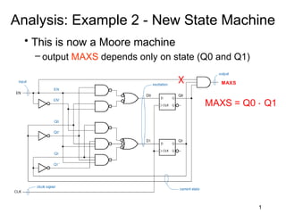
  • 1. Analysis: Example 2 - New State Machine • This is now a Moore machine – output MAXS depends only on state (Q0 and Q1) MAXS MAXS = Q0 ⋅ Q1 1
  • 2. Analysis: Example 2 - New Table/Diagram • Updated State/Output Table & Diagram – Moore machine state diagram output associated with state, not transition 2
  • 3. Analysis: Example 2 - Timing Diagram • Timing Diagram for State Machine – Compare outputs MAX and MAXS for the Mealy and Moore machine implementations 3
  • 4. Conversion of Models • Mealy to Moore machine – If all the transitions in a Mealy model to a particular state are associated with the same output then in the corresponding Moore model that output becomes the state output. T1 T1 1/0 1 T2 1/0 1/0 T2 1 A 1 B A B 0 0 0/1 0 0/0 0 T3 T4 T3 T4 Mealy Moore
  • 5. Conversion of Models • Mealy to Moore machine – If the outputs of all the transitions in a Mealy model to a particular state are not the same, then in the corresponding Moore model we need to insert intermediate states T1 T1 T4 1/0 1 0 T2 0/0 1/0 T2 0 A0 B 1 A B 0 0 0/1 1/1 T3 T4 A1 1 T3 1 Mealy 1 0 Moore T4
  • 6. Conversion of Models • Moore to Mealy machine – If the state transition from two different states of the same input leads to common state then one state can be eliminated T1 T1 1 1/0 T2 0 A0 B T2 0/0 1/0 1 A B 0 0 1/1 1 A1 1 T3 T3 1 Moore Mealy
  • 7. Conversion of Models • Moore to Mealy machine – If the state transition from two different states of the same input does not lead to the same state, then state output becomes the output corresponding to each input transition of that state T1 T1 1 1/0 T2 A B T2 0/0 0/0 0 0 A B 0 0 1 1 1/0 1/1 C T3 T3 C Moore 1 Mealy
  • 8. Analysis: Example 3 - State Machine X Y Q0 Q1 J0 = X·Y' K0 = X·Y' + Y·Q1 Q0' Q1' J0 Q0 J Q K0 K Q J1 = X·Q0 + Y J1 Q1 J Q K1 K Q Z Clk K1 = Y·Q0' + X·Y'·Q0 Z = X·Q0·Q1 + Q0'·Q1'·Y
  • 9. 1. Determine the excitation equations for the flip flop inputs J 0 = X ⋅Y ′ J 1 = X ⋅ Q0 + Y K 0 = X ⋅ Y ′ + Y ⋅ Q1 K1 = Y ⋅ Q0′ + X ⋅ Y ′ ⋅ Q0 2. Substitute the excitation equations into the flip flop characteristic equations to obtain transition equations. Q0* = J 0 ⋅ Q0′ + K 0′Q 0 characteristic equations Q1* = J 1 ⋅ Q1′ + K1′Q1 ′ Q 0* = ( X ⋅ Y ′) ⋅ Q0′ + ( X ⋅ Y ′ + Y ⋅ Q1) Q 0 transition equations ′ Q1* = ( X ⋅ Q0 + Y ) ⋅ Q1′ + ( Y ⋅ Q0′ + X ⋅ Y ′ ⋅ Q 0 ) Q1
  • 10. Simplifying the transition equations Q0* = ( X ⋅ Y ′) ⋅ Q0′ + ( X ⋅ Y ′ + Y ⋅ Q1) ′ Q 0 Q 0* = ( X ⋅ Y ) ⋅ Q0 + ( ( X ⋅ Y ) + ( Y ⋅ Q1) ) ⋅ Q0 ( ) Q0* = X ⋅ Y ⋅ Q 0 + ( X ⋅ Y ) ⋅ ( Y ⋅ Q1) ⋅ Q0 ( )( Q0* = X ⋅ Y ⋅ Q0 + X + Y ⋅ Y + Q1 ⋅ Q0 )) Q0* = X ⋅ Y ⋅ Q0 + ( ( X + Y ) ⋅ (Y + Q1) ) ⋅ Q0 Q0* = X ⋅ Y ⋅ Q0 + ( X ⋅ Y + X ⋅ Q1 + Y ⋅ Y + Y ⋅ Q1) ⋅ Q0 Q 0* = X ⋅ Y ′ ⋅ Q 0′ + X ′ ⋅ Y ′ ⋅ Q0 + X ′ ⋅ Q0 ⋅ Q1′ + Y ⋅ Q0 ⋅ Q1′
  • 11. Simplifying the transition equations Q1* = ( X ⋅ Q0 + Y ) ⋅ Q1′ + ( Y ⋅ Q0′ + X ⋅ Y ′ ⋅ Q 0 ) ′ Q1 (( ) ( Q1* = ( X ⋅ Q0 + Y ) ⋅ Q1 + Y ⋅ Q0 + X ⋅ Y ⋅ Q0 ⋅ Q1 )) Q1* = X ⋅ Q0 ⋅ Q1 + Y ⋅ Q1 + ( Y ⋅ Q0 ) ⋅ ( X ⋅ Y ⋅ Q0 ) ) ⋅ Q1 ( )( Q1* = X ⋅ Q0 ⋅ Q1 + Y ⋅ Q1 + Y + Q0 ⋅ X + Y + Q0 ⋅ Q1 ) (( )( Q1* = X ⋅ Q0 ⋅ Q1 + Y ⋅ Q1 + Y + Q0 ⋅ X + Y + Q0 ⋅ Q1 )) ( Q1* = XQ0Q1 + Y Q1 + X Y + Y Y + Y Q0 + X Q 0 + YQ0 + Q0Q0 ⋅ Q1 ) Q1* = X ⋅ Q0 ⋅ Q1′ + Y ⋅ Q1′ + X ′ ⋅ Y ′ ⋅ Q1 + Y ′ ⋅ Q 0′ ⋅ Q1 + X ′ ⋅ Q0 ⋅ Q1 + Y ⋅ Q0 ⋅ Q1 3. Determine the output equations. Z = X ⋅ Q0 ⋅ Q1 + Y ⋅ Q0′ ⋅ Q1′ output equation
  • 12. 4. Use transition equations and output equations to construct transition/output table. Transition/output table State Input XY Q1Q0 00 01 10 11 00 00,0 10,1 01,0 10,1 01 01,0 11,0 10,0 11,0 10 10,0 00,0 11,0 00,0 11 11,0 10,0 00,1 10,1 Next State Q1*Q0*, Z
  • 13. 6. Name the states and substitute state names for state – variable combinations in the transition/output table to obtain the state/output table. State/output table Substituting the state names as ‘A’ State Input XY for Q1Q0 = 00, ‘B’ for Q1Q0 = 01, S 00 01 10 11 ‘C’ for Q1Q0 = 10, ‘D’ for Q1Q0 = 11. A A,0 C,1 B,0 C,1 S is current state & S* is next state. B B,0 D,0 C,0 D,0 C C,0 A,0 D,0 A,0 D D,0 C,0 A,1 C,1 Next State S*, Z
  • 14. State diagram 10/0 00/0 A B 00/0 01,11/1 01,11/0 10/1 10/0 01,11/0 11/1 00/0 D C 00/0 01/0 10/0
  • 15. Synchronous Design Process 1. Construct a state diagram and/or state/output table corresponding to the word description or specification 2. Minimize the number of states 3. Choose a set of state variables and assign state variable combinations to the named states 4. Obtain the transition/output table 5. Determine the number of flip-flops and select the type of flip-flop to be used (D is often the default) 6. Construct the excitation table 7. Derive excitation equations 8. Derive output equations 15
  • 16. Design a clocked synchronous state machine which accepts two serial strings of digits of arbitrary length, starting with LSB and produces the sum and carry of the two bit streams as its output. The input bit streams could come from two shift registers clocked simultaneously . Assuming Mealy machine design Let the inputs be X and Y Let the outputs be S and C
  • 17. Obtaining the state Diagram Assume initial condition to be SC = 00 Let the state be represented by state A If XY = 00, then output SC = 00, Same state A = 01, then output SC = 10, goes to state B XY/SC = 10, then output SC = 10, goes to state B 01,10/10 00/00 A B = 11, then output SC = 01, goes to state C 11/01 C
  • 18. Obtaining the state Diagram Assume machine has moved to state B If XY = 00, then output SC = 00, goes to state A = 01, then output SC = 10, same state B = 10, then output SC = 10, same state XY/SC B 01,10/10 = 11, then output SC = 01, goes to 00/00 A B 01,10/10 state C 00/00 11/01 11/01 C
  • 19. Obtaining the state Diagram Assume machine has moved to state C If XY = 00, then output SC = 10, goes to state B = 01, then output SC = 01, same state C = 10, then output SC = 01, same state XY/SC C 01,10/10 = 11, then output SC = 11, goes to 00/00 A B 01,10/10 state D 00/00 11/01 11/01 00/10 11/11 01,10/01 C D
  • 20. Obtaining the state Diagram Assume machine has moved to state D If XY = 00, then output SC = 10, goes to state B = 01, then output SC = 01, goes to state C XY/SC = 10, then output SC = 01, goes to 01,10/10 state C 01,10/10 00/00 A B 00/00 = 11, then output SC = 11, same state D 11/01 11/01 00/10 00/10 11/11 11/11 01,10/01 C D 01,10/01
  • 21. Obtaining the state/output table State/output table State Input XY S 00 01 10 11 A A,00 B,10 B,10 C,01 B A,00 B,10 B,10 C,01 C B,10 C,01 C,01 D,11 D B,10 C,01 C,01 D,11 Next State S*, SC
  • 22. Equivalent States Two states are equivalent if it is impossible to distinguish them by observing only the current and future outputs of the machine . A pair of equivalent states can be replaced by a single state. Two states S1 and S2 are equivalent if two conditions are true. 1. S1 and S2 must produce the same values at the state machine output(s) for all input combinations. 2. For each input combination S1 and S2 must
  • 23. State Minimization Equivalen State/output table t states State Input XY S 00 01 10 11 A A,00 B,10 B,10 C,01 B A,00 B,10 B,10 C,01 C B,10 C,01 C,01 D,11 D B,10 C,01 C,01 D,11 Next State S*, SC Equivalent states
  • 24. Minimized state/output table & state diagram State/output table State Input XY S 00 01 10 11 A A,00 A,10 A,10 D,01 D A,10 D,01 D,01 D,11 Next State S*, SC 00/00 01/01 11/01 01/10 10/01 A D 10/10 11/11 00/10 State diagram
  • 25. Assigning state variable to obtain transition/output table Transition/output table State Input XY Q 00 01 10 11 0 0,00 0,10 0,10 1,01 1 0,10 1,01 1,01 1,11 Next State Q*, SC Encoding A = 0 and D = 1 Choosing D type flip flop
  • 26. Constructing the excitation table Excitation/output table State Input XY Q 00 01 10 11 0 0,00 0,10 0,10 1,01 1 0,10 1,01 1,01 1,11 D, SC
  • 27. Transferring onto K-maps to derive excitation & output equations Excitation/output table State Input XY Q 00 01 10 11 0 0,00 0,10 0,10 1,01 1 0,10 1,01 1,01 1,11 State Input XY D, SC Q 00 01 11 10 D = X· Y + X · Q +Y · Q 0 0 0 1 0 C = X· Y + X · Q +Y · Q 1 0 1 1 1
  • 28. Transferring onto K-maps to derive excitation & output equations Excitation/output table State Input XY Q 00 01 10 11 0 0,00 0,10 0,10 1,01 1 0,10 1,01 1,01 1,11 State Input XY D, SC Q 00 01 11 10 S = X ⋅Y ⋅ Q + X ⋅Y ⋅ Q 0 0 1 0 1 + X ⋅Y ⋅ Q + X ⋅Y ⋅ Q 1 1 0 1 0 S = X ⊕Y ⊕Q
  • 29. Circuit (logic) diagram D = X· Y + X · Q +Y · Q excitation equation S = X ⊕ Y ⊕ Q C = X· Y + X · Q +Y · Qoutput equations X Y Q C S D Q Q Clk