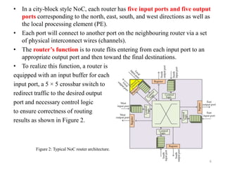
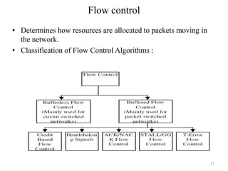
Visvesvaraya Technological University, Belagavi – 590018
SDM COLLEGE OF ENGINEERING & TECHNOLOGY,
DHARWAD-02
Department of Electronics and Communication Engineering
Presentation on
“Network on a Chip(NoC)”
Prepared by
Mr. MANJYA NAIK R
( 3rd semester, M.Tech, DE)
Department of E&CE, SDMCET, Dharwad
1
What is Network on a Chip?
• A network on a chip or network-on-chip (NoC ) is a network-
based communications subsystem on an integrated circuit ("microchip"),
most typically between modules in a system on a chip (SoC).
• The network on chip is a router-based packet switching network between
SoC modules.
• Networks-on-chip improve the scalability of systems-on-chip and
the power efficiency of complex SoCs compared to other communication
subsystem designs.
• Used in computer graphics, video gaming and accelerating artificial
intelligence.
2
Network on a chip has the following features:
• Network on a chip helps in simplifying the hardware required for routing
and switching functions.
• Multi-topology and multi-option support is possible for different areas of
the network.
• Scalability, interoperability and feature development are enhanced when
combined with network on a chip.
• Power efficiency of complex system-on-chips is improved with network
on a chip compared to other designs.
• Synchronization issues are handled better than in other designs.
• Network on a chip provides higher operating frequencies.
• Timing closure is much easier to implement.
• Verification of problems is much easier.
3
Network on a Chip
Characteristics:
• Topology
• Routing algorithms
• Switching strategy
• Flow control
4
Network-on-Chip Architecture
• A typical NoC architecture consists of multiple
segments of wires and routers as shown in
Figure 1.
• In a tiled, city-block style of NoC layout, the
wires and routers are configured much like
street grids of a city, while the clients (e.g.,
logic processor cores) are placed on city blocks
separated by wires.
• A network interface (NI) module transforms
data packets generated from the client logic
(processor cores) into fixed-length flow-
control digits (flits).
• The flits associated with a data packet consist
of a header (or head) flit, a tail flit, and a
number of body flits in between.
• This array of flits will be routed toward the
intended destination in a hop-by-hop manner
from one router to its neighbouring router.
Fig 1. Typical NoC architecture in a mesh topology.
5
• In a city-block style NoC, each router has five input ports and five output
ports corresponding to the north, east, south, and west directions as well as
the local processing element (PE).
• Each port will connect to another port on the neighbouring router via a set
of physical interconnect wires (channels).
• The router’s function is to route flits entering from each input port to an
appropriate output port and then toward the final destinations.
• To realize this function, a router is
equipped with an input buffer for each
input port, a 5 Ă— 5 crossbar switch to
redirect traffic to the desired output
port and necessary control logic
to ensure correctness of routing
results as shown in Figure 2.
Figure 2: Typical NoC router architecture.
6
Cont..
• Usually, for each data packet, the corresponding head flit specifies its
intended destination.
• After examining the head flit, the router control logic will determine
which output direction to route all the subsequent (body and tail) flits
associated with this data packet according to the routing algorithm applied.
7
NoC Topologies
• Regular/irregular
• Direct/indirect
– each node has a direct point-to-point link to a
subset of other nodes in the system, called
neighboring nodes
8
2D Mesh
IP IP IP
IP IP IP
IP IP IP
R R R
R R R
R R R
•Simplest and most
popular topology for
NoCs.
•Every switch, except
those at the edges, is
connected to four
neighboring switches
and one node.
9
2D Torus
IP
R
IP
R
IP
R
IP
R
IP
R
IP
R
IP
R
IP
R
IP
R
IP
R
IP
R
IP
R
IP
R
IP
R
IP
R
IP
R•Layout of a regular mesh
except that nodes at the edges
are connected to switches at
the opposite edge via wrap-
around routing channels.
•Every switch has five ports
•The limitation of this
topology affects the long end-
around connections
10
Octagon
IP
IPIP
IPIP
IP
IPIP
RR
R
R
R
R
RR
•Well-established direct topology
found in NoCs.
•Ring of 8 nodes connected by 12
bi-directional links.
•Links provide two-hop
communication between any pair
of nodes in the ring
11
Fat-tree and butterfly fat-tree
• Nodes are connected to an
architecture's external switch
• Switches have point-to-point links to
other switches.
• Processing units and memory
modules are assigned to the leafs of
the trees,
• Switches are placed at the vertices,
• Communication involves climbing up
and down some part of the tree.
R
IP IP
R
IP IP
R
IP IP
R
IP IP
R
R R
IPIPIP IPIPIP IPIPIP IPIPIP
R
R R R R
R
12
Polygon
• Widely accepted topology
• Packets travel in a loop
from one router to the
next.
• Add chords to the circle
• If chords are inserted only
between opposite routers,
the topology is called a
spidergon.
R
IPIP
R
R R
R R
IPIP
IP IP
13
Star
• Central router in the middle of the star,
• Computational resources, or subnetworks, in the spikes of the star.
• The capacity requirements of the central router are quite large,
• Significant possibility of congestion in the middle of the star
IP
IP
IPIP
IP
R CORE
IP
R R
R R
IP
IP
IP
14
Routing
• Classification of Routing Algorithms :
15
Switching
• Classification of Switching Techniques :
16
Flow control
• Determines how resources are allocated to packets moving in
the network.
• Classification of Flow Control Algorithms :
17
Summary
• NoC is an exciting research area that will lead to an paradigm
shift in SoC design.
• NoC research is still in infancy
– Many open research problems
– Need better application and traffic models, new
optimization techniques
• New Power, Performance, Traffic Models being developed
18
Thank you
19

Ppt seminar noc

  • 1.
    Visvesvaraya Technological University,Belagavi – 590018 SDM COLLEGE OF ENGINEERING & TECHNOLOGY, DHARWAD-02 Department of Electronics and Communication Engineering Presentation on “Network on a Chip(NoC)” Prepared by Mr. MANJYA NAIK R ( 3rd semester, M.Tech, DE) Department of E&CE, SDMCET, Dharwad 1
  • 2.
    What is Networkon a Chip? • A network on a chip or network-on-chip (NoC ) is a network- based communications subsystem on an integrated circuit ("microchip"), most typically between modules in a system on a chip (SoC). • The network on chip is a router-based packet switching network between SoC modules. • Networks-on-chip improve the scalability of systems-on-chip and the power efficiency of complex SoCs compared to other communication subsystem designs. • Used in computer graphics, video gaming and accelerating artificial intelligence. 2
  • 3.
    Network on achip has the following features: • Network on a chip helps in simplifying the hardware required for routing and switching functions. • Multi-topology and multi-option support is possible for different areas of the network. • Scalability, interoperability and feature development are enhanced when combined with network on a chip. • Power efficiency of complex system-on-chips is improved with network on a chip compared to other designs. • Synchronization issues are handled better than in other designs. • Network on a chip provides higher operating frequencies. • Timing closure is much easier to implement. • Verification of problems is much easier. 3
  • 4.
    Network on aChip Characteristics: • Topology • Routing algorithms • Switching strategy • Flow control 4
  • 5.
    Network-on-Chip Architecture • Atypical NoC architecture consists of multiple segments of wires and routers as shown in Figure 1. • In a tiled, city-block style of NoC layout, the wires and routers are configured much like street grids of a city, while the clients (e.g., logic processor cores) are placed on city blocks separated by wires. • A network interface (NI) module transforms data packets generated from the client logic (processor cores) into fixed-length flow- control digits (flits). • The flits associated with a data packet consist of a header (or head) flit, a tail flit, and a number of body flits in between. • This array of flits will be routed toward the intended destination in a hop-by-hop manner from one router to its neighbouring router. Fig 1. Typical NoC architecture in a mesh topology. 5
  • 6.
    • In acity-block style NoC, each router has five input ports and five output ports corresponding to the north, east, south, and west directions as well as the local processing element (PE). • Each port will connect to another port on the neighbouring router via a set of physical interconnect wires (channels). • The router’s function is to route flits entering from each input port to an appropriate output port and then toward the final destinations. • To realize this function, a router is equipped with an input buffer for each input port, a 5 × 5 crossbar switch to redirect traffic to the desired output port and necessary control logic to ensure correctness of routing results as shown in Figure 2. Figure 2: Typical NoC router architecture. 6
  • 7.
    Cont.. • Usually, foreach data packet, the corresponding head flit specifies its intended destination. • After examining the head flit, the router control logic will determine which output direction to route all the subsequent (body and tail) flits associated with this data packet according to the routing algorithm applied. 7
  • 8.
    NoC Topologies • Regular/irregular •Direct/indirect – each node has a direct point-to-point link to a subset of other nodes in the system, called neighboring nodes 8
  • 9.
    2D Mesh IP IPIP IP IP IP IP IP IP R R R R R R R R R •Simplest and most popular topology for NoCs. •Every switch, except those at the edges, is connected to four neighboring switches and one node. 9
  • 10.
    2D Torus IP R IP R IP R IP R IP R IP R IP R IP R IP R IP R IP R IP R IP R IP R IP R IP R•Layout ofa regular mesh except that nodes at the edges are connected to switches at the opposite edge via wrap- around routing channels. •Every switch has five ports •The limitation of this topology affects the long end- around connections 10
  • 11.
    Octagon IP IPIP IPIP IP IPIP RR R R R R RR •Well-established direct topology foundin NoCs. •Ring of 8 nodes connected by 12 bi-directional links. •Links provide two-hop communication between any pair of nodes in the ring 11
  • 12.
    Fat-tree and butterflyfat-tree • Nodes are connected to an architecture's external switch • Switches have point-to-point links to other switches. • Processing units and memory modules are assigned to the leafs of the trees, • Switches are placed at the vertices, • Communication involves climbing up and down some part of the tree. R IP IP R IP IP R IP IP R IP IP R R R IPIPIP IPIPIP IPIPIP IPIPIP R R R R R R 12
  • 13.
    Polygon • Widely acceptedtopology • Packets travel in a loop from one router to the next. • Add chords to the circle • If chords are inserted only between opposite routers, the topology is called a spidergon. R IPIP R R R R R IPIP IP IP 13
  • 14.
    Star • Central routerin the middle of the star, • Computational resources, or subnetworks, in the spikes of the star. • The capacity requirements of the central router are quite large, • Significant possibility of congestion in the middle of the star IP IP IPIP IP R CORE IP R R R R IP IP IP 14
  • 15.
    Routing • Classification ofRouting Algorithms : 15
  • 16.
    Switching • Classification ofSwitching Techniques : 16
  • 17.
    Flow control • Determineshow resources are allocated to packets moving in the network. • Classification of Flow Control Algorithms : 17
  • 18.
    Summary • NoC isan exciting research area that will lead to an paradigm shift in SoC design. • NoC research is still in infancy – Many open research problems – Need better application and traffic models, new optimization techniques • New Power, Performance, Traffic Models being developed 18
  • 19.