Downloaded 149 times

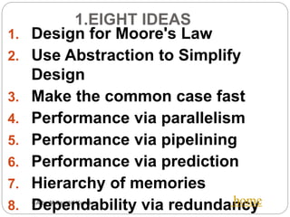
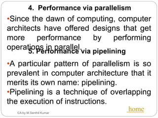
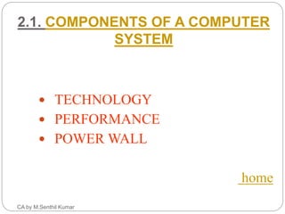
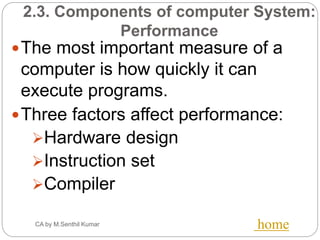
![4.1 Instruction Formats
(Contd..)
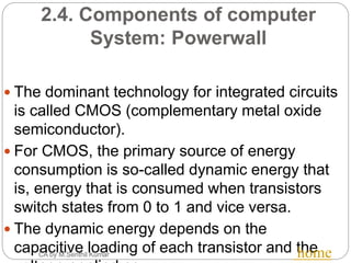
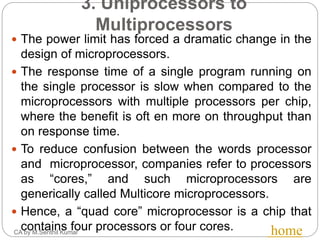
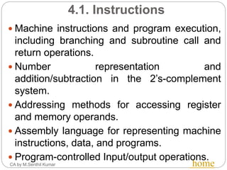
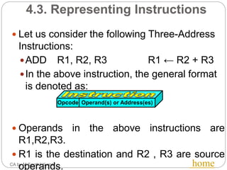
Three-Address Instructions
ADD R1, R2, R3 R1 ← R2 + R3
Two-Address Instructions
ADD R1, R2 R1 ← R1 + R2
One-Address Instructions
ADD M AC ← AC + M[AR]
Zero-Address Instructions
ADD TOS ← TOS + (TOS – 1)
RISC Instructions
Lots of registers. Memory is restricted to Load & Store
Opcode Operand(s) or Address(es)](https://image.slidesharecdn.com/ca-unit1pres-161118101155/85/CS6303-Computer-Architecture-25-320.jpg)
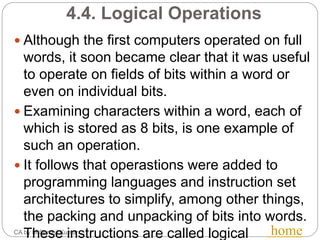
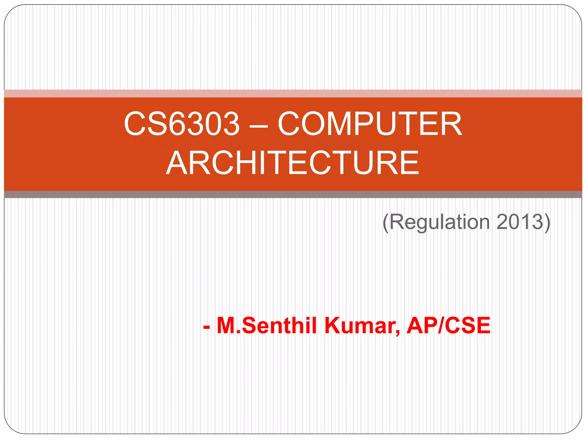
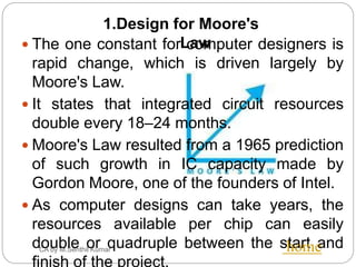
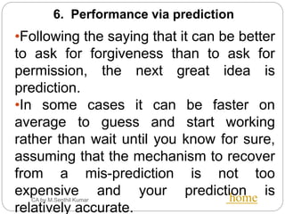
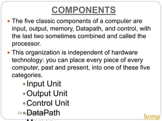
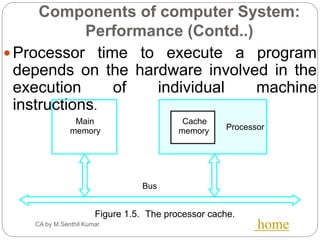
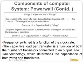
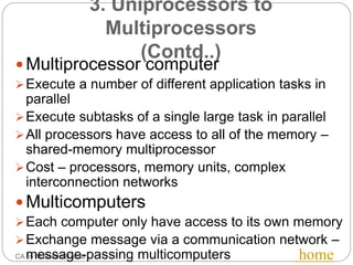
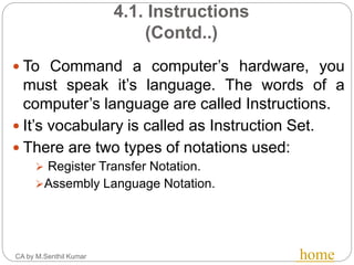
![4.6. Addressing and Addressing
Modes
CA by M.Senthil Kumar home
Name Assembler syntax Addressingfunction
Immediate #Value Operand = Value
Register Ri EA = Ri
Absolute(Direct) LOC EA = LOC
Indirect (Ri ) EA = [Ri ]
(LOC) EA = [LOC]
Index X(Ri) EA = [Ri ] + X
Basewith index (Ri ,Rj ) EA = [Ri ] + [Rj ]
Basewith index X(Ri,Rj ) EA = [Ri ] + [Rj ] + X
and offset
Relative X(PC) EA = [PC] + X
Autoincrement (Ri )+ EA = [Ri ] ;
Increment Ri
Autodecrement (Ri ) Decrement Ri ;
EA = [Ri]
The
different
ways in
which the
location
of an
operand
is
specified
in an
instructio
n are
referred
to as
addressin
g modes.](https://image.slidesharecdn.com/ca-unit1pres-161118101155/85/CS6303-Computer-Architecture-32-320.jpg)

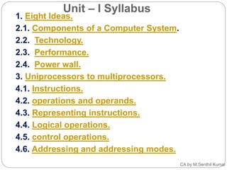
This document provides an overview of the syllabus for the course CS6303 - Computer Architecture. It covers the following key topics in 3 sentences or less: - Components of a computer system including input, output, memory, datapath, and control. Instructions and their representation. Addressing modes for accessing operands. - Eight major ideas in computer architecture: designing for Moore's law, using abstraction, optimizing common cases, performance via parallelism and pipelining, performance via prediction, hierarchy of memories, and dependability via redundancy. - Evolution from uniprocessors to multiprocessors to address power constraints. Instruction formats, operations, logical and control operations, and different addressing modes for specifying operand locations