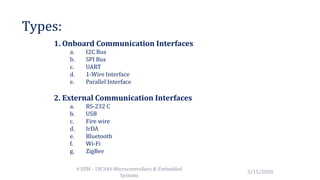
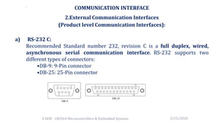
COMMUNICATION INTERFACE
4 SEM - 18CS44-Microcontrollers & Embedded Systems 5/15/2020
Types:
4 SEM - 18CS44-Microcontrollers & Embedded
Systems
5/15/2020
1. Onboard Communication Interfaces
a. I2C Bus
b. SPI Bus
c. UART
d. 1-Wire Interface
e. Parallel Interface
2. External Communication Interfaces
a. RS-232 C
b. USB
c. Fire wire
d. IrDA
e. Bluetooth
f. Wi-Fi
g. ZigBee
1.Onboard Communication Interfaces
(Device/Board level Communication Interfaces):
a)Inter Integrated Circuit (I2C) Bus:
It is a synchronous bi-directional half-duplex two wire serial
interface bus.
– The I2C bus comprise of two bus lines:
• Serial Clock (SCL line) – responsible for generating synchronization
clock pulses
• Serial Data (SDA line) – responsible for transmitting
– I2C bus is a shared bus system to which many number of I2C devices can be
connected. Devices connected to the I2C bus can act as either 'Master' or
'Slave’.
5/15/20204 SEM - 18CS44-Microcontrollers & Embedded Systems
• The 'Master' device is responsible for controlling the communication.
• 'Slave' devices wait for the commands from the master and respond.
• The synchronization clock signal is generated by the 'Master' device only.
• I2C supports multi masters on the same bus
• Both the bus lines should be pulled to the supply voltage using pull-up
resistors. The typical value of resistors used in pull-up is 2.2K.
The sequence of operations for communicating
with an I2C slave device is listed below:
• The master device pulls the clock line (SCL) to 'HIGH'
• The master device pulls the data line (SDA) 'LOW
• The master device sends the address of the ‘slave’
• The master device sends the Read or Write bit
• The master device waits for the acknowledgement bit from the slave
device
• The slave device with the address requested by the master device
responds by sending an acknowledge bit (Bit value 1) over the SDA line
• Upon receiving the acknowledge bit, the Master device starts the
communication.
5/15/20204 SEM - 18CS44-Microcontrollers & Embedded Systems
b)Serial Peripheral Interface (SPI) Bus:
– The Serial Peripheral Interface Bus (SPI) is a
synchronous bi-directional full duplex four-wire serial
interface bus.
– The concept of SPI was introduced by Motorola.
– SPI is a single master multi-slave system.
5/15/20204 SEM - 18CS44-Microcontrollers & Embedded Systems
SPI requires four signal lines for communication. They are:
• Master Out Slave In (MOSI) – Signal line carrying the data from master to slave
device. It is also known as Slave Input/SIave Data In (SI/SDI)
• Master In Slave Out (MISO) – Signal line carrying the data from slave to master
device. It is also known as Slave Output (SO/SDO)
• Serial Clock (SCLK) – Signal line carrying the clock signals
• Slave Select (SS) – Signal line for slave device select. It is an active low signal
• Master selects the required slave device by asserting the
corresponding slave select signal 'LOW’.
• The serial data transmission through SPI bus is fully configurable
• SPI devices contain a certain set of registers which are Serial
peripheral control register & status register
• SPI works on the principle of 'Shift Register’
• The master and slave devices contain a special shift register for the
data to transmit or receive.
• The shift registers of 'master' and 'slave' devices form a circular
buffer
5/15/20204 SEM - 18CS44-Microcontrollers & Embedded Systems
c) Universal Asynchronous Receiver Transmitter (UART):
– Universal Asynchronous Receiver Transmitter (UART) based data transmission is an
asynchronous form of serial data transmission.
– It doesn't require a clock signal to synchronize the transmitting end and receiving
end for transmission.
– Instead it relies upon the pre-defined agreement between the transmitting device
and receiving device.
– The serial communication settings for both transmitter and receiver should be set as
identical.
– The start and stop of communication is indicated through inserting special bits in the
data stream.
– If parity is enabled for communication, the transmitting device adds a parity bit. This
is for error checking
– The UART of the receiving device discards the 'Start', 'Stop' and 'Parity’ bit
5/15/20204 SEM - 18CS44-Microcontrollers & Embedded Systems
d)1-Wire Interface:
• 1-wire interface is an asynchronous half-duplex communication
protocol developed by Maxim Dallas Semiconductor
• It makes use of only a single signal line (wire) called DQ
• One of the key features of 1-wire bus is that it allows power to be sent
• Every 1-wire device contains a unique 64bit identification number stored
within it.
• The identifier has three parts: an 8 bit family code, a 48 bit serial number
and an 8 bit CRC.
5/15/20204 SEM - 18CS44-Microcontrollers & Embedded Systems
The sequence of operation for communicating with a 1-wire slave device is listed
below:
• The master device sends a 'Reset' pulse on the 1-wire bus.
• The slave device(s) respond with a 'Presence' pulse.
• The master device sends a Net Address Command followed by the 64-bit
address of the device.
• The master device sends a read/write function command bit.
• The master initiates a Read data/Write data from the device or to the device
5/15/20204 SEM - 18CS44-Microcontrollers & Embedded Systems
e) Parallel Interface:
• The on-board parallel interface is used for communicating with
peripheral devices which are memory mapped to the host of the system
• The communication through the parallel bus is controlled by the control
signal interface
• Only the host processor has control over the 'Read' and 'Write' control
signals.
• The external device is normally memory mapped to the host processor
and a range of address is assigned to it.
• When the address selected by the processor, the processor then can read
or write from or to the device by asserting the corresponding control line
(RD and WR respectively).
5/15/20204 SEM - 18CS44-Microcontrollers & Embedded Systems
COMMUNICATION INTERFACE
2.External Communication Interfaces
(Product level Communication Interfaces):
a) RS-232 C:
Recommended Standard number 232, revision C is a full duplex, wired,
asynchronous serial communication interface. RS-232 supports two
different types of connectors:
•DB-9: 9-Pin connector
•DB-25: 25-Pin connector
5/15/20204 SEM - 18CS44-Microcontrollers & Embedded Systems
.
• The RS-232 interface defines various handshaking and control signals for communication
• There are Data Terminal Equipment(DTE) and Data Communication Equipment(DCE) in RS
232.
• If no data flow control is required, only TXD and RXD signal lines and ground line (GND) are
required for data transmission and reception.
• If hardware data flow control is required for serial transmission, various control signal lines
of the RS- 232 connection are used appropriately.
• The Request to Send (RTS),Clear To Send (CTS), Data Terminal Ready(DTR) and Data Set
Ready(DSR) signals co-ordinate the communication between DTE and DCE.
• As per the EIA standard RS-232 C supports baud rates up to 20Kbps (Upper limit 19.2 Kbps)
• The commonly used baud rates by devices are 300bps, 1200bps, 2400bps, 9600bps,
11.52Kbps and 19.2Kbps.
5/15/20204 SEM - 18CS44-Microcontrollers & Embedded Systems
b) Universal Serial Bus (USB):
• Universal Serial Bus (USB) is a wired high-speed serial bus for
data communication.
• The USB communication system follows a star topology with a USB
host at the Centre and one or more USB peripheral devices/USB
hosts connected to it.
5/15/2020
4 SEM - 18CS44-Microcontrollers & Embedded
Systems
• USB transmits data in packet format
• The USB communication is a host initiated one.
• The USB host contains a host controller
• The physical connection between a USB peripheral device
and master device is established with a USB cable which
supports communication distance of up to 5 metres
• USB interface has the ability to supply power to the
connecting devices
• It can supply power up to 500 mA at 5 V.
5/15/20204 SEM - 18CS44-Microcontrollers & Embedded Systems
 USB supports four different types of data transfers
– Control transfer : Used by USB system software
– Bulk transfer: Used for sending a block of data
– Isochronous data transfer: Used for real-time data
communication.
– Interrupt transfer: Used for transferring small amount of
data
5/15/2020
4 SEM - 18CS44-Microcontrollers &
Embedded Systems
c) IEEE 1394 (Fire wire):
– IEEE 1394 is a wired, isochronous high-speed serial communication bus.
– It is also known as High Performance Serial Bus (HPSB). It supports 400-
3200Mbps data rate.
– The interface cable supports 3 types of connectors, namely; 4-pin connector, 6-pin
Connector (alpha connector) and 9 pin connector (beta connector).
– The 6 and 9 pin connectors carry power.
– IEEE 1394 doesn't require a host for communicating between devices. For example,
you can directly connect a scanner with a printer for printing
5/15/2020
4 SEM - 18CS44-Microcontrollers & Embedded
Systems
COMMUNICATION INTERFACE
2.External Communication Interfaces
(Product level Communication Interfaces):
d) Infrared (IrDA):
• Infrared (IrDA) is a serial, half duplex, line of sight
based wireless technology for data communication.
• Infrared communication technique uses infrared waves of the
electromagnetic spectrum for transmitting the data.
• It supports point-point and point-to-multipoint communication
• The communication range for IrDA lies in the range 10 cm to 1
m.
• IR supports data rates ranging from 9600bits/second to
16Mbps.
5/15/2020
4 SEM - 18CS44-Microcontrollers & Embedded
Systems
Depending on the speed of data transmission IR is
classified into:
 Serial IR (SIR) – supports data rates ranging from 9600bps to 115.2kbps.
 Medium IR (MIR) – supports data rates of 0.576Mbps and 1.152Mbps.
 Fast IR (FIR) – supports data rates up to 4Mbps.
 Very Fast IR (VFIR) – supports high data rates up to 16Mbps.
 Ultra Fast IR (UFIR) – targeted to support a data rate up to 100Mbps
IrDA communication, Infrared Light Emitting Diode (LED) is the IR
source for transmitter and at the receiving end a photodiode acts as
the receiver.
5/15/20204 SEM - 18CS44-Microcontrollers & Embedded Systems
e) Bluetooth (BT):
– Bluetooth is a low cost, low power, short range wireless technology
for data and voice communication.
– Bluetooth operates at 2.4GHz of the Radio Frequency spectrum and
uses the Frequency Hopping Spread Spectrum (FHSS) technique for
communication.
– It supports a data rate of up to 1Mbps and a range of 30 feet for data
communication.
– Bluetooth communication has two parts – a physical link part and a
protocol part.
5/15/20204 SEM - 18CS44-Microcontrollers & Embedded Systems
– Each Bluetooth device will have a 48-bit unique
identification number
– Bluetooth supports point-to-point and point-to-multipoint
wireless communication.
– The point-to-point communication follows the master-slave
relationship.
– Bluetooth is the favorite choice for short range data
communication in handheld embedded devices.
5/15/20204 SEM - 18CS44-Microcontrollers & Embedded Systems
f) Wi-Fi:
– Wireless Fidelity is the popular wireless communication
technique for networked communication of devices.
– Wi-Fi follows the IEEE 802.11 standard.
– Wi-Fi is intended for network communication and it supports
Internet Protocol (IP) based communication.
5/15/20204 SEM - 18CS44-Microcontrollers & Embedded Systems
• IP address and Wi-Fi router/Wireless Access Point are
required for Wi-Fi based communication.
• Wi-Fi router is responsible for restricting access to the
network, assigning IP address to the devices, routing data
packets to the intended devices.
• Wi-Fi enabled devices will be having wireless adaptor.
• Wi-Fi operates at 2.4GHz or 5GHz of Radio spectrum.
5/15/20204 SEM - 18CS44-Microcontrollers & Embedded Systems
g)ZigBee:
• ZigBee is a low power, low cost, wireless network communication protocol
based on the IEEE 802.15.4-2006 standard.
• ZigBee operates worldwide at the unlicensed bands of Radio spectrum, mainly
at 2.400 to 2.484 GHz, 902 to 928 MHz and 868.0 to 868.6 MHz
• ZigBee supports an operating distance of up to 100 metres and a data rate of
20 to 250 Kbps
5/15/20204 SEM - 18CS44-Microcontrollers & Embedded Systems
In the ZigBee terminology, each ZigBee device falls under any one
of the following ZigBee device category:
– ZigBee Coordinator (ZC)/Network Coordinator
• The ZigBee coordinator acts as the root of the ZigBee network.
– ZigBee Router (ZR)/Full function Device (FFD)
• Responsible for passing information from device to another device
or to another ZR.
– ZigBee End Device (ZED)/Reduced Function Device (RFD)
• End device containing ZigBee functionality for data
communication.
• It can talk only with a ZR or ZC and doesn't have the capability to
act as a mediator for transferring data from one device to another.
5/15/20204 SEM - 18CS44-Microcontrollers & Embedded Systems

Communication Interface of The Embedded Systems

  • 1.
    COMMUNICATION INTERFACE 4 SEM- 18CS44-Microcontrollers & Embedded Systems 5/15/2020
  • 2.
    Types: 4 SEM -18CS44-Microcontrollers & Embedded Systems 5/15/2020 1. Onboard Communication Interfaces a. I2C Bus b. SPI Bus c. UART d. 1-Wire Interface e. Parallel Interface 2. External Communication Interfaces a. RS-232 C b. USB c. Fire wire d. IrDA e. Bluetooth f. Wi-Fi g. ZigBee
  • 3.
    1.Onboard Communication Interfaces (Device/Boardlevel Communication Interfaces): a)Inter Integrated Circuit (I2C) Bus: It is a synchronous bi-directional half-duplex two wire serial interface bus. – The I2C bus comprise of two bus lines: • Serial Clock (SCL line) – responsible for generating synchronization clock pulses • Serial Data (SDA line) – responsible for transmitting – I2C bus is a shared bus system to which many number of I2C devices can be connected. Devices connected to the I2C bus can act as either 'Master' or 'Slave’. 5/15/20204 SEM - 18CS44-Microcontrollers & Embedded Systems
  • 4.
    5/15/20204 SEM -18CS44-Microcontrollers & Embedded Systems • The 'Master' device is responsible for controlling the communication. • 'Slave' devices wait for the commands from the master and respond. • The synchronization clock signal is generated by the 'Master' device only. • I2C supports multi masters on the same bus • Both the bus lines should be pulled to the supply voltage using pull-up resistors. The typical value of resistors used in pull-up is 2.2K.
  • 5.
    The sequence ofoperations for communicating with an I2C slave device is listed below: • The master device pulls the clock line (SCL) to 'HIGH' • The master device pulls the data line (SDA) 'LOW • The master device sends the address of the ‘slave’ • The master device sends the Read or Write bit • The master device waits for the acknowledgement bit from the slave device • The slave device with the address requested by the master device responds by sending an acknowledge bit (Bit value 1) over the SDA line • Upon receiving the acknowledge bit, the Master device starts the communication. 5/15/20204 SEM - 18CS44-Microcontrollers & Embedded Systems
  • 6.
    b)Serial Peripheral Interface(SPI) Bus: – The Serial Peripheral Interface Bus (SPI) is a synchronous bi-directional full duplex four-wire serial interface bus. – The concept of SPI was introduced by Motorola. – SPI is a single master multi-slave system. 5/15/20204 SEM - 18CS44-Microcontrollers & Embedded Systems
  • 7.
    5/15/20204 SEM -18CS44-Microcontrollers & Embedded Systems SPI requires four signal lines for communication. They are: • Master Out Slave In (MOSI) – Signal line carrying the data from master to slave device. It is also known as Slave Input/SIave Data In (SI/SDI) • Master In Slave Out (MISO) – Signal line carrying the data from slave to master device. It is also known as Slave Output (SO/SDO) • Serial Clock (SCLK) – Signal line carrying the clock signals • Slave Select (SS) – Signal line for slave device select. It is an active low signal
  • 8.
    • Master selectsthe required slave device by asserting the corresponding slave select signal 'LOW’. • The serial data transmission through SPI bus is fully configurable • SPI devices contain a certain set of registers which are Serial peripheral control register & status register • SPI works on the principle of 'Shift Register’ • The master and slave devices contain a special shift register for the data to transmit or receive. • The shift registers of 'master' and 'slave' devices form a circular buffer 5/15/20204 SEM - 18CS44-Microcontrollers & Embedded Systems
  • 9.
    c) Universal AsynchronousReceiver Transmitter (UART): – Universal Asynchronous Receiver Transmitter (UART) based data transmission is an asynchronous form of serial data transmission. – It doesn't require a clock signal to synchronize the transmitting end and receiving end for transmission. – Instead it relies upon the pre-defined agreement between the transmitting device and receiving device. – The serial communication settings for both transmitter and receiver should be set as identical. – The start and stop of communication is indicated through inserting special bits in the data stream. – If parity is enabled for communication, the transmitting device adds a parity bit. This is for error checking – The UART of the receiving device discards the 'Start', 'Stop' and 'Parity’ bit 5/15/20204 SEM - 18CS44-Microcontrollers & Embedded Systems
  • 10.
    5/15/20204 SEM -18CS44-Microcontrollers & Embedded Systems
  • 11.
    d)1-Wire Interface: • 1-wireinterface is an asynchronous half-duplex communication protocol developed by Maxim Dallas Semiconductor • It makes use of only a single signal line (wire) called DQ • One of the key features of 1-wire bus is that it allows power to be sent • Every 1-wire device contains a unique 64bit identification number stored within it. • The identifier has three parts: an 8 bit family code, a 48 bit serial number and an 8 bit CRC. 5/15/20204 SEM - 18CS44-Microcontrollers & Embedded Systems
  • 12.
    The sequence ofoperation for communicating with a 1-wire slave device is listed below: • The master device sends a 'Reset' pulse on the 1-wire bus. • The slave device(s) respond with a 'Presence' pulse. • The master device sends a Net Address Command followed by the 64-bit address of the device. • The master device sends a read/write function command bit. • The master initiates a Read data/Write data from the device or to the device 5/15/20204 SEM - 18CS44-Microcontrollers & Embedded Systems
  • 13.
    e) Parallel Interface: •The on-board parallel interface is used for communicating with peripheral devices which are memory mapped to the host of the system • The communication through the parallel bus is controlled by the control signal interface • Only the host processor has control over the 'Read' and 'Write' control signals. • The external device is normally memory mapped to the host processor and a range of address is assigned to it. • When the address selected by the processor, the processor then can read or write from or to the device by asserting the corresponding control line (RD and WR respectively). 5/15/20204 SEM - 18CS44-Microcontrollers & Embedded Systems
  • 14.
    5/15/20204 SEM -18CS44-Microcontrollers & Embedded Systems
  • 15.
    COMMUNICATION INTERFACE 2.External CommunicationInterfaces (Product level Communication Interfaces): a) RS-232 C: Recommended Standard number 232, revision C is a full duplex, wired, asynchronous serial communication interface. RS-232 supports two different types of connectors: •DB-9: 9-Pin connector •DB-25: 25-Pin connector 5/15/20204 SEM - 18CS44-Microcontrollers & Embedded Systems .
  • 16.
    • The RS-232interface defines various handshaking and control signals for communication • There are Data Terminal Equipment(DTE) and Data Communication Equipment(DCE) in RS 232. • If no data flow control is required, only TXD and RXD signal lines and ground line (GND) are required for data transmission and reception. • If hardware data flow control is required for serial transmission, various control signal lines of the RS- 232 connection are used appropriately. • The Request to Send (RTS),Clear To Send (CTS), Data Terminal Ready(DTR) and Data Set Ready(DSR) signals co-ordinate the communication between DTE and DCE. • As per the EIA standard RS-232 C supports baud rates up to 20Kbps (Upper limit 19.2 Kbps) • The commonly used baud rates by devices are 300bps, 1200bps, 2400bps, 9600bps, 11.52Kbps and 19.2Kbps. 5/15/20204 SEM - 18CS44-Microcontrollers & Embedded Systems
  • 17.
    b) Universal SerialBus (USB): • Universal Serial Bus (USB) is a wired high-speed serial bus for data communication. • The USB communication system follows a star topology with a USB host at the Centre and one or more USB peripheral devices/USB hosts connected to it. 5/15/2020 4 SEM - 18CS44-Microcontrollers & Embedded Systems
  • 18.
    • USB transmitsdata in packet format • The USB communication is a host initiated one. • The USB host contains a host controller • The physical connection between a USB peripheral device and master device is established with a USB cable which supports communication distance of up to 5 metres • USB interface has the ability to supply power to the connecting devices • It can supply power up to 500 mA at 5 V. 5/15/20204 SEM - 18CS44-Microcontrollers & Embedded Systems
  • 19.
     USB supportsfour different types of data transfers – Control transfer : Used by USB system software – Bulk transfer: Used for sending a block of data – Isochronous data transfer: Used for real-time data communication. – Interrupt transfer: Used for transferring small amount of data 5/15/2020 4 SEM - 18CS44-Microcontrollers & Embedded Systems
  • 20.
    c) IEEE 1394(Fire wire): – IEEE 1394 is a wired, isochronous high-speed serial communication bus. – It is also known as High Performance Serial Bus (HPSB). It supports 400- 3200Mbps data rate. – The interface cable supports 3 types of connectors, namely; 4-pin connector, 6-pin Connector (alpha connector) and 9 pin connector (beta connector). – The 6 and 9 pin connectors carry power. – IEEE 1394 doesn't require a host for communicating between devices. For example, you can directly connect a scanner with a printer for printing 5/15/2020 4 SEM - 18CS44-Microcontrollers & Embedded Systems
  • 21.
    COMMUNICATION INTERFACE 2.External CommunicationInterfaces (Product level Communication Interfaces): d) Infrared (IrDA): • Infrared (IrDA) is a serial, half duplex, line of sight based wireless technology for data communication. • Infrared communication technique uses infrared waves of the electromagnetic spectrum for transmitting the data. • It supports point-point and point-to-multipoint communication • The communication range for IrDA lies in the range 10 cm to 1 m. • IR supports data rates ranging from 9600bits/second to 16Mbps. 5/15/2020 4 SEM - 18CS44-Microcontrollers & Embedded Systems
  • 22.
    Depending on thespeed of data transmission IR is classified into:  Serial IR (SIR) – supports data rates ranging from 9600bps to 115.2kbps.  Medium IR (MIR) – supports data rates of 0.576Mbps and 1.152Mbps.  Fast IR (FIR) – supports data rates up to 4Mbps.  Very Fast IR (VFIR) – supports high data rates up to 16Mbps.  Ultra Fast IR (UFIR) – targeted to support a data rate up to 100Mbps IrDA communication, Infrared Light Emitting Diode (LED) is the IR source for transmitter and at the receiving end a photodiode acts as the receiver. 5/15/20204 SEM - 18CS44-Microcontrollers & Embedded Systems
  • 23.
    e) Bluetooth (BT): –Bluetooth is a low cost, low power, short range wireless technology for data and voice communication. – Bluetooth operates at 2.4GHz of the Radio Frequency spectrum and uses the Frequency Hopping Spread Spectrum (FHSS) technique for communication. – It supports a data rate of up to 1Mbps and a range of 30 feet for data communication. – Bluetooth communication has two parts – a physical link part and a protocol part. 5/15/20204 SEM - 18CS44-Microcontrollers & Embedded Systems
  • 24.
    – Each Bluetoothdevice will have a 48-bit unique identification number – Bluetooth supports point-to-point and point-to-multipoint wireless communication. – The point-to-point communication follows the master-slave relationship. – Bluetooth is the favorite choice for short range data communication in handheld embedded devices. 5/15/20204 SEM - 18CS44-Microcontrollers & Embedded Systems
  • 25.
    f) Wi-Fi: – WirelessFidelity is the popular wireless communication technique for networked communication of devices. – Wi-Fi follows the IEEE 802.11 standard. – Wi-Fi is intended for network communication and it supports Internet Protocol (IP) based communication. 5/15/20204 SEM - 18CS44-Microcontrollers & Embedded Systems
  • 26.
    • IP addressand Wi-Fi router/Wireless Access Point are required for Wi-Fi based communication. • Wi-Fi router is responsible for restricting access to the network, assigning IP address to the devices, routing data packets to the intended devices. • Wi-Fi enabled devices will be having wireless adaptor. • Wi-Fi operates at 2.4GHz or 5GHz of Radio spectrum. 5/15/20204 SEM - 18CS44-Microcontrollers & Embedded Systems
  • 27.
    g)ZigBee: • ZigBee isa low power, low cost, wireless network communication protocol based on the IEEE 802.15.4-2006 standard. • ZigBee operates worldwide at the unlicensed bands of Radio spectrum, mainly at 2.400 to 2.484 GHz, 902 to 928 MHz and 868.0 to 868.6 MHz • ZigBee supports an operating distance of up to 100 metres and a data rate of 20 to 250 Kbps 5/15/20204 SEM - 18CS44-Microcontrollers & Embedded Systems
  • 28.
    In the ZigBeeterminology, each ZigBee device falls under any one of the following ZigBee device category: – ZigBee Coordinator (ZC)/Network Coordinator • The ZigBee coordinator acts as the root of the ZigBee network. – ZigBee Router (ZR)/Full function Device (FFD) • Responsible for passing information from device to another device or to another ZR. – ZigBee End Device (ZED)/Reduced Function Device (RFD) • End device containing ZigBee functionality for data communication. • It can talk only with a ZR or ZC and doesn't have the capability to act as a mediator for transferring data from one device to another. 5/15/20204 SEM - 18CS44-Microcontrollers & Embedded Systems