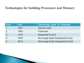
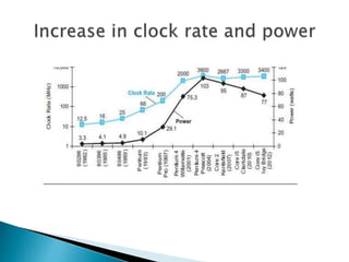
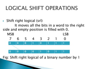
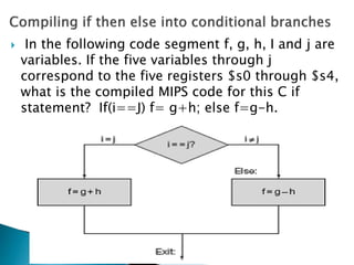
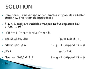
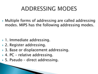
The document summarizes key concepts from the textbook "Computer Organization and Design" by David A. Patterson and John L. Hennessey. It discusses the fundamental components of computer systems, including the processor, control unit, registers, memory, and I/O. It then outlines several important principles for improving computer performance, such as designing for Moore's Law, using abstraction, optimizing common cases, exploiting parallelism through pipelining and prediction. The document also discusses metrics for measuring performance and trends in processor clock rates, power consumption, and integrated circuit technology.


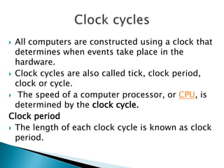


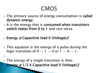
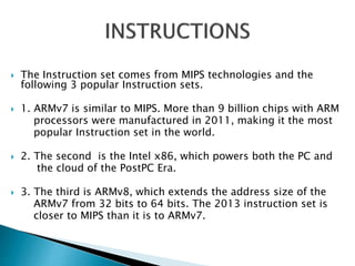
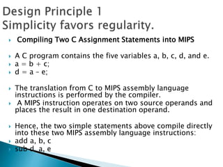
![ The power required per transistor is the product of
energy of a transition and the frequency of
transitions
Power α Energy X Frequency switched
[or]
Power α 1/2 X Capacitive load X (Voltage)2 X
Frequency switched
Frequency switched is a function of the clock rate.
The capacitive load per transistor is a function of
both the number of transistors connected to an
output (called the fan out).](https://image.slidesharecdn.com/caunitippt-230419060958-4f1468ab/85/CA-UNIT-I-PPT-ppt-52-320.jpg)
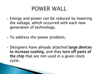


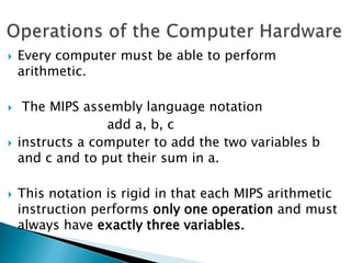
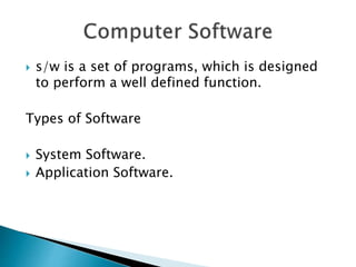
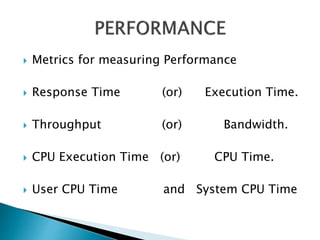
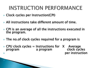
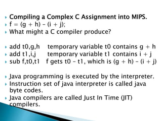
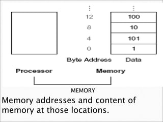
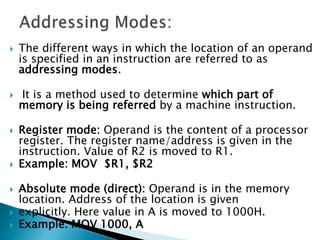
![ DATA TRANSFER
INSTRUCTION EXAMPLE MEANING
load word lw $s1,20($s2) s1 = Memory[$s2 + 20]
COMMENT : Word from memory to register.
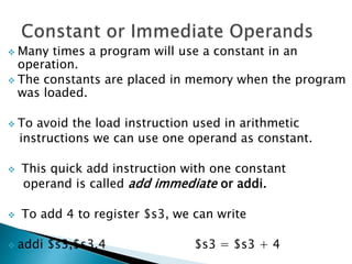
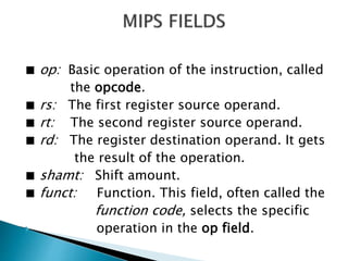
To keep the hardware simple, every instruction
should have exactly three operands.](https://image.slidesharecdn.com/caunitippt-230419060958-4f1468ab/85/CA-UNIT-I-PPT-ppt-61-320.jpg)

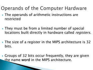
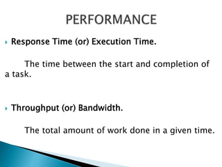
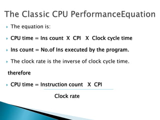
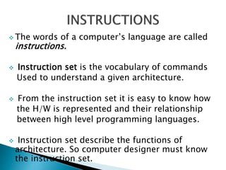
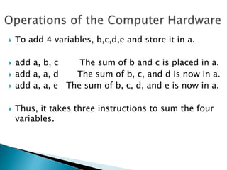
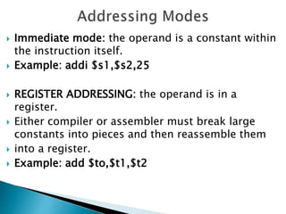
![ A is an array of 100 words and that the compiler
has associated the variables g and h with the
registers $s1 and $s2.
Let the starting address, or base address, of the
array is in $s3.
Compile this C assignment statement:
g = h + A[8]](https://image.slidesharecdn.com/caunitippt-230419060958-4f1468ab/85/CA-UNIT-I-PPT-ppt-71-320.jpg)
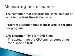
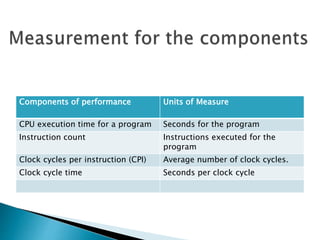
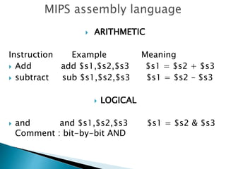
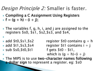
![ Although there is a single operation in this
assignment statement, one of the operands is in
memory, so we must first transfer A[8] to a
register.
The address of this array element is the sum of the
base of the array A, found in register $s3, plus the
number to select element 8.[i.e] 8($s3).
The data should be placed in a temporary register
for use in the next instruction.[i.e] $t0.
](https://image.slidesharecdn.com/caunitippt-230419060958-4f1468ab/85/CA-UNIT-I-PPT-ppt-72-320.jpg)
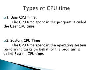
![ The first compiled instruction is
lw $t0,8($s3) Temporary reg $t0 gets A[8].
The second compiled instruction is
add $s1,$s2,$t0 g = h + A[8].
The constant in a data transfer instruction (8) is called
the off set.
The register added to form the address ($s3) is called
the base register.](https://image.slidesharecdn.com/caunitippt-230419060958-4f1468ab/85/CA-UNIT-I-PPT-ppt-74-320.jpg)
![ while (save[i] == k)
i += 1;
Assume that i and k correspond to registers $s3 and $s5 and the base
of the array save is in $s6.
Loop: sll $t1,$s3,2 Temp reg $t1 = i * 4
To get the address of save[i], we need to add $t1 and the base of save
in $s6:
add $t1,$t1,$s6 $t1 = address of save[i]
Now we can use that address to load save[i] into a temporary register:
lw $t0,0($t1) Temp reg $t0 = save[i]
The next instruction performs the loop test, exiting if save[i] ≠ k:
bne $t0,$s5, Exit go to Exit if save[i] ≠ k
The next instruction adds 1 to i
addi $s3,$s3,1 i = i + 1 :
The end of the loop branches back to the while test at the top of the
loop. We just add the Exit label after it
j Loop go to Loop
Exit:](https://image.slidesharecdn.com/caunitippt-230419060958-4f1468ab/85/CA-UNIT-I-PPT-ppt-97-320.jpg)
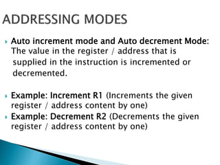
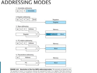
![ Base or Displacement Addressing: the operand is
at the memory location whose address is the sum
of a register and a constant in the instruction.
Example: g = h + A[8]
PC-relative addressing: the branch address is the sum
of the PC and a constant in the instruction.
Pseudodirect addressing, where the jump address
is the 26 bits of the instruction concatenated with
the upper bits of the PC.
Example: blt $to, $zero $s1
blt – branch on less than.](https://image.slidesharecdn.com/caunitippt-230419060958-4f1468ab/85/CA-UNIT-I-PPT-ppt-102-320.jpg)