The document provides an introduction to the course on computer organization and architecture. It discusses key concepts like:
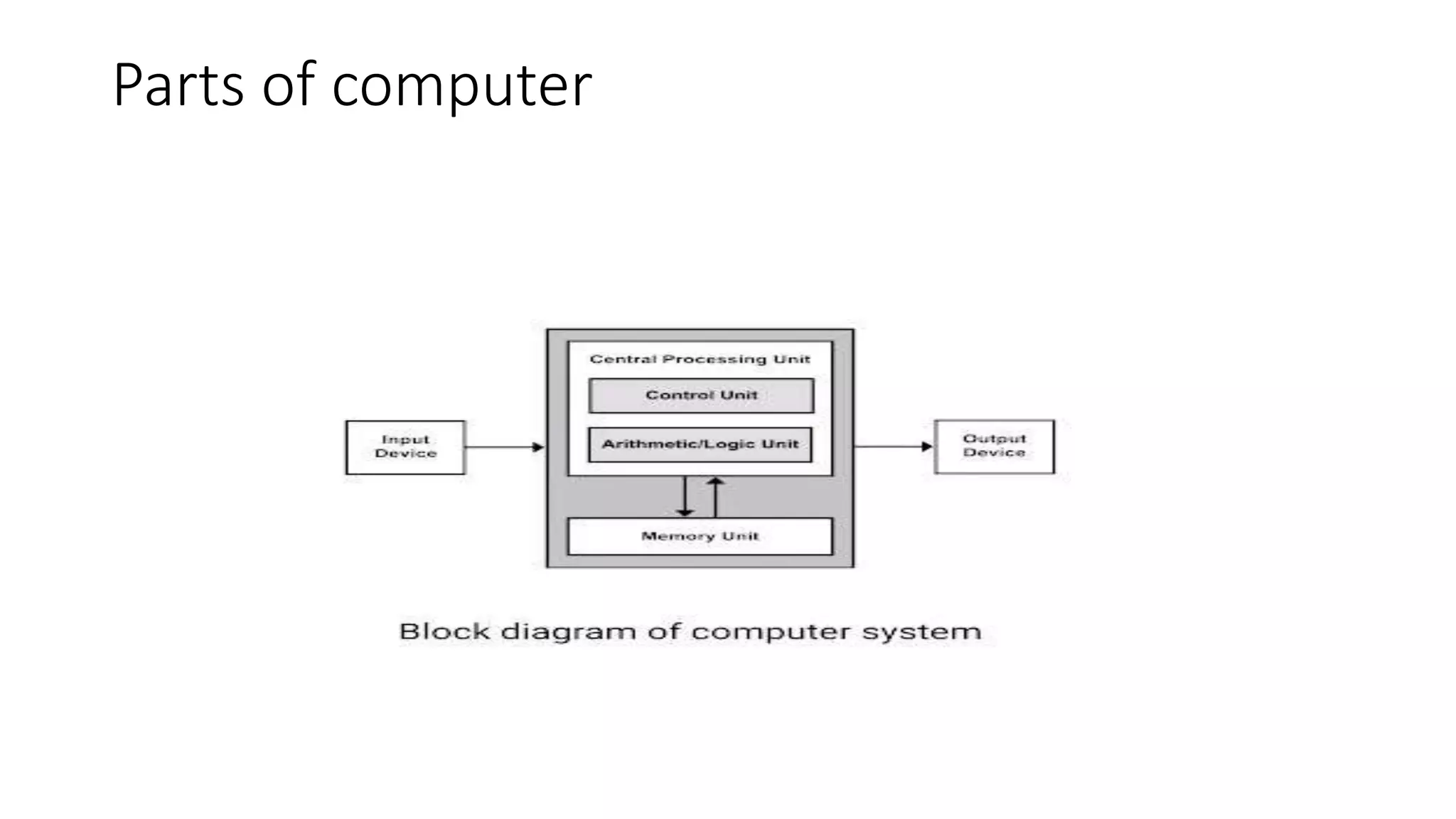
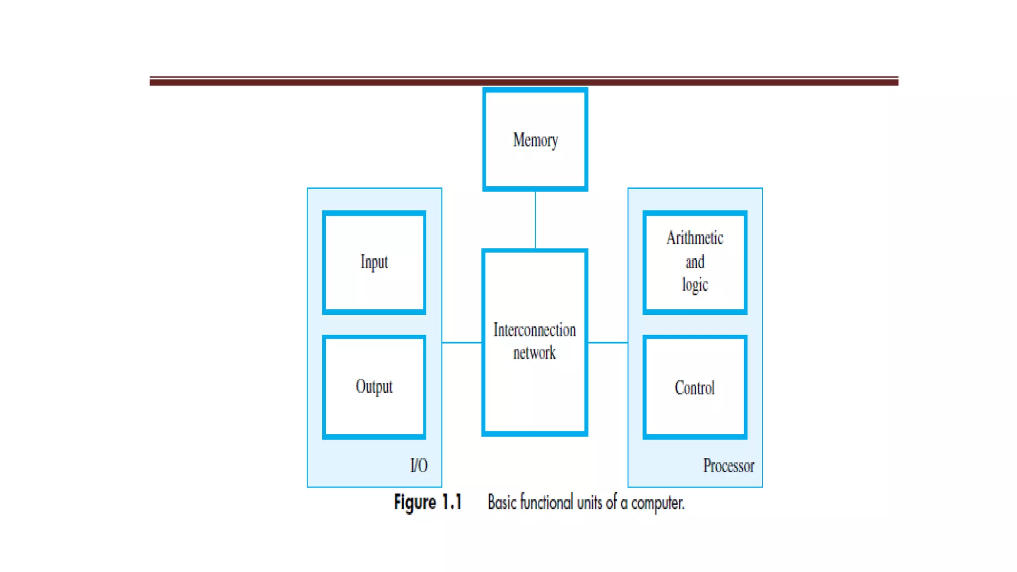
- Where data is stored, processed, and displayed in a computer.
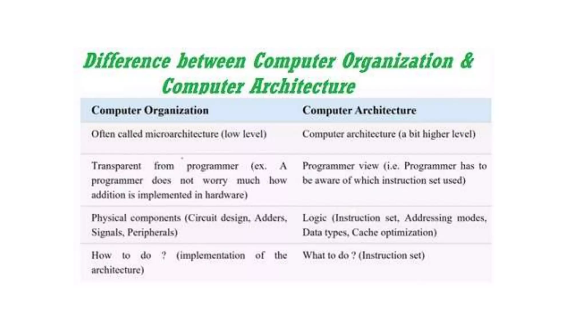
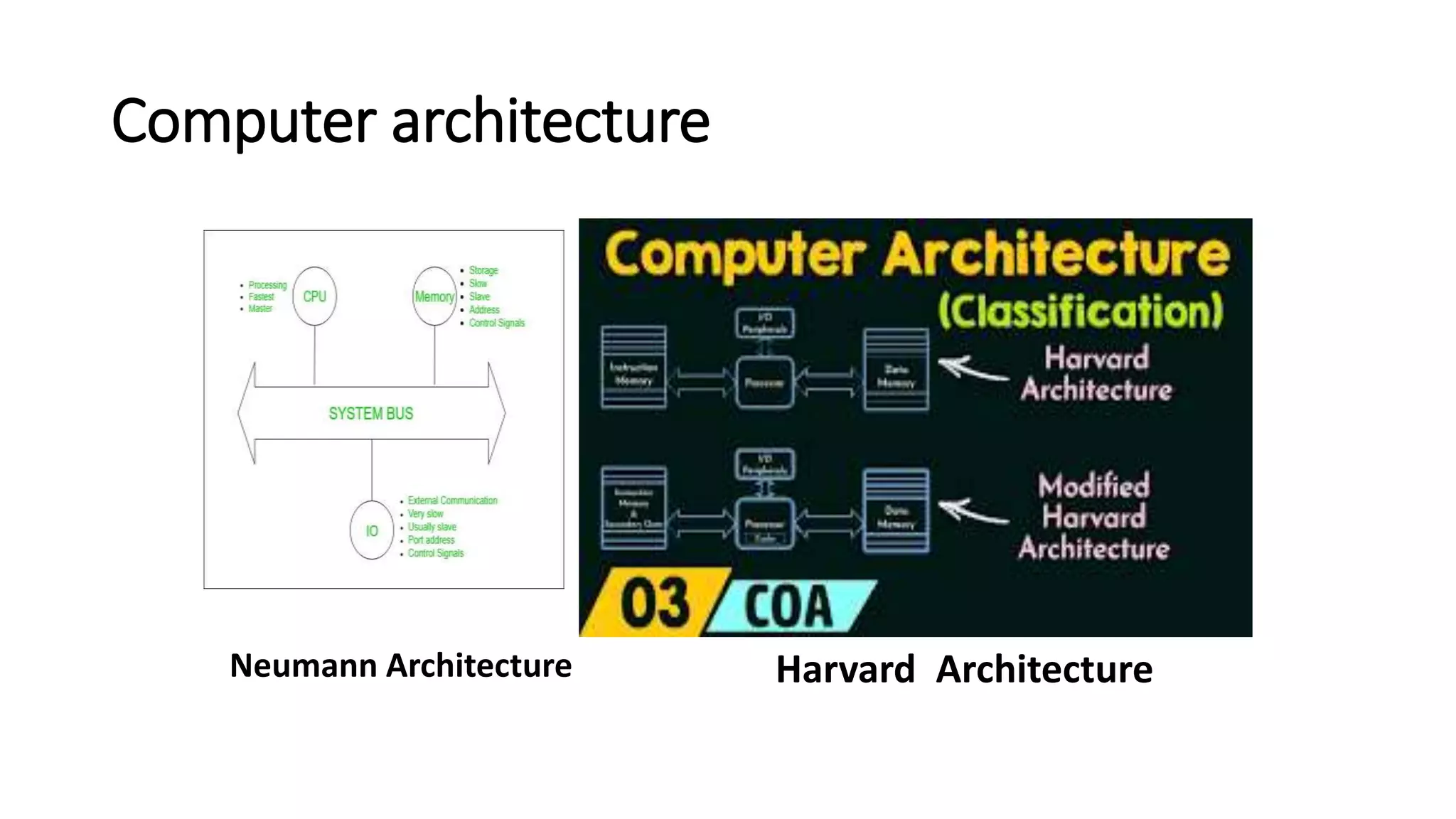
- Computer architecture deals with the functional behavior and design implementation of computer systems. Computer organization deals with the structural relationships and utilization within a computer system.
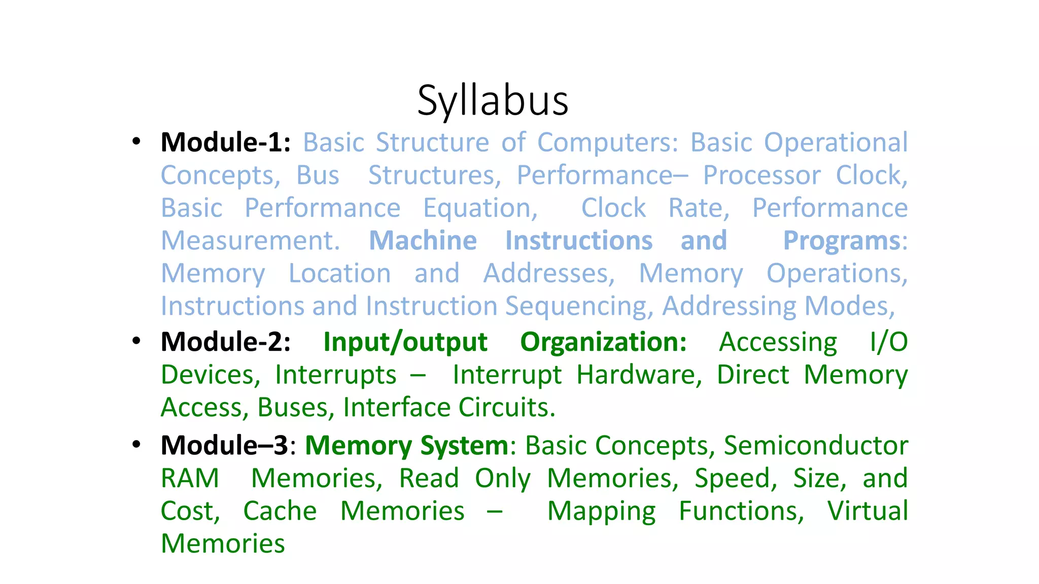
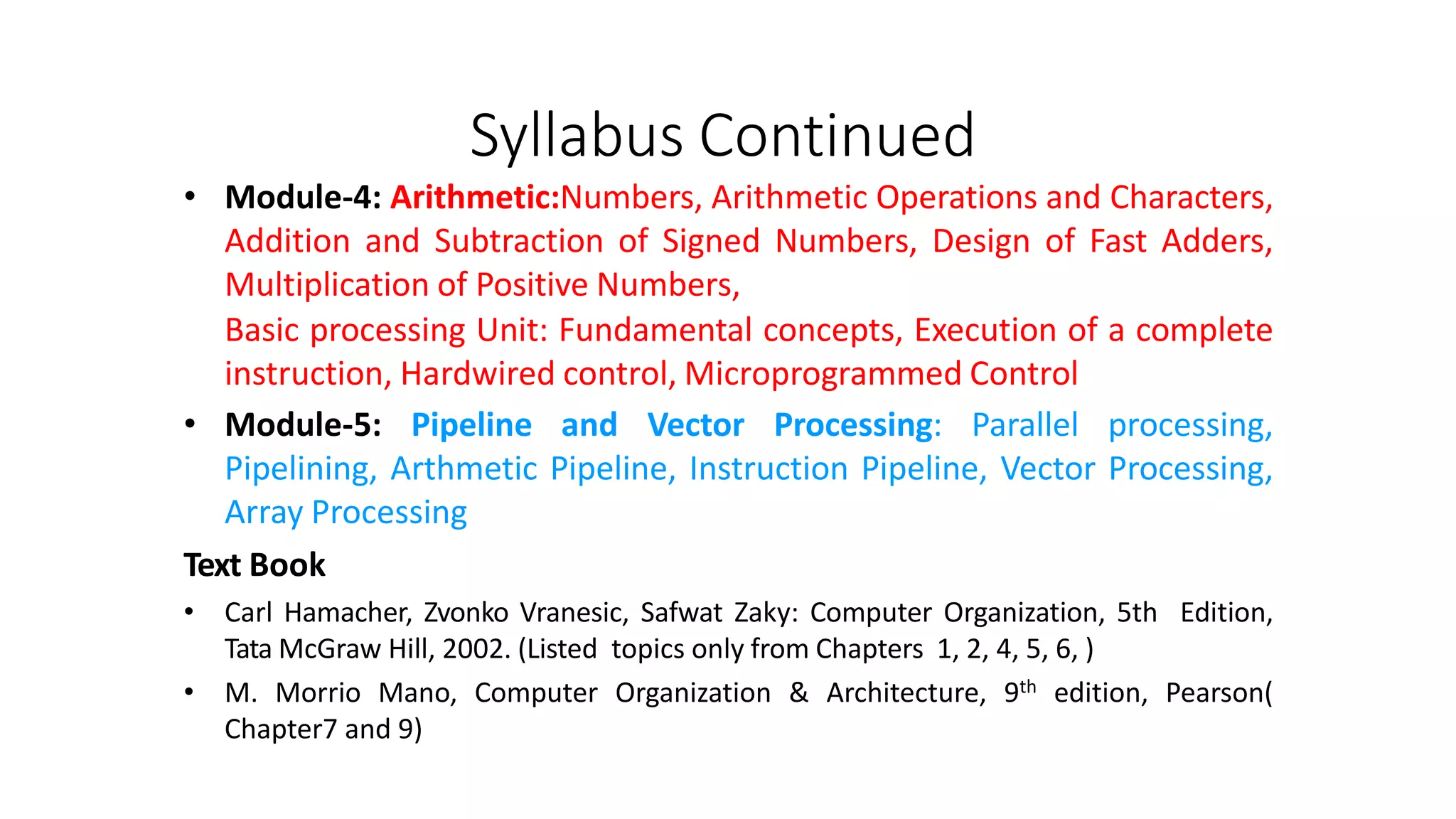
- The document outlines the syllabus which will cover topics like basic computer structure, memory systems, arithmetic and logical operations, and parallel processing techniques like pipelining and vector processing.
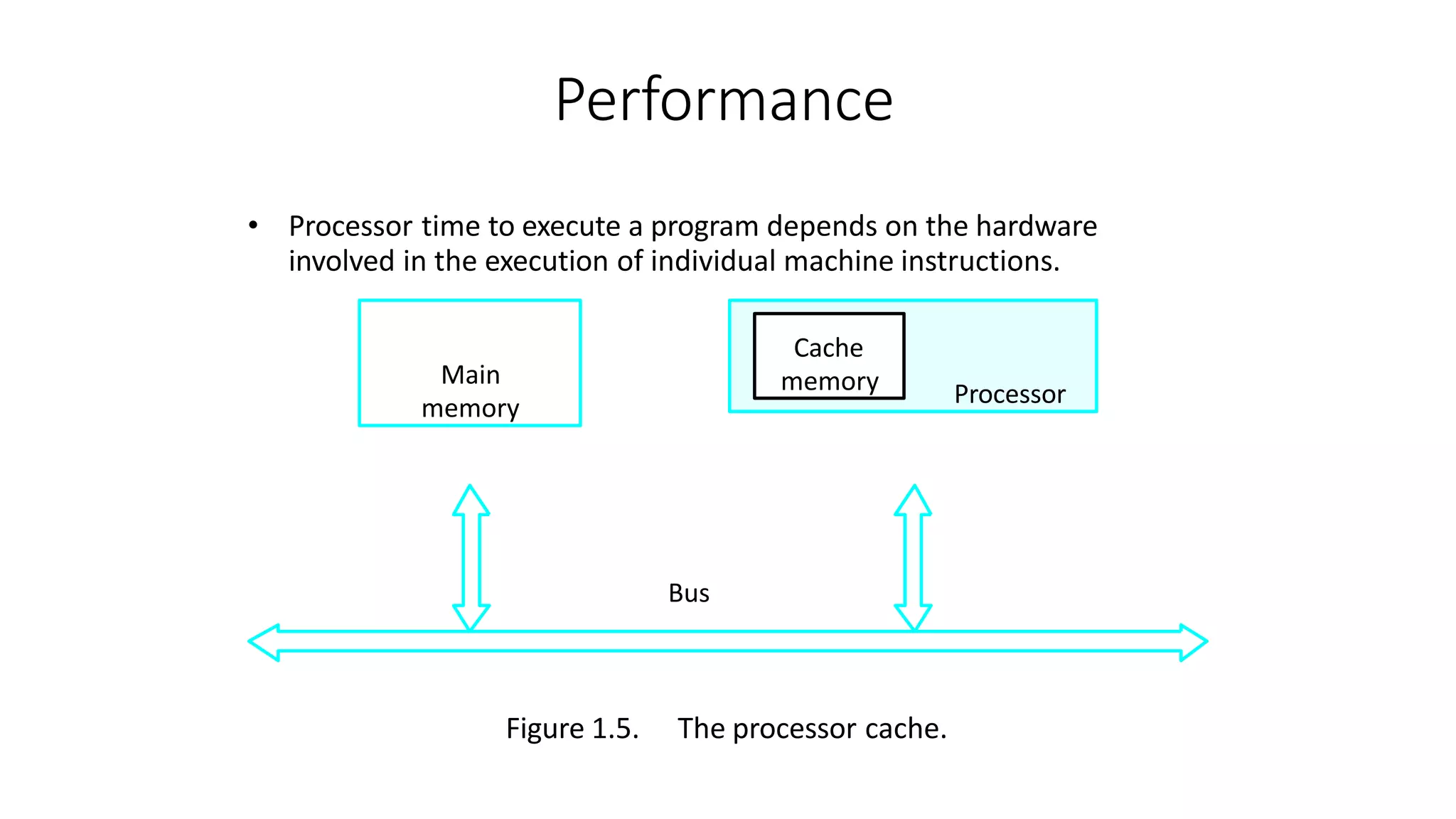
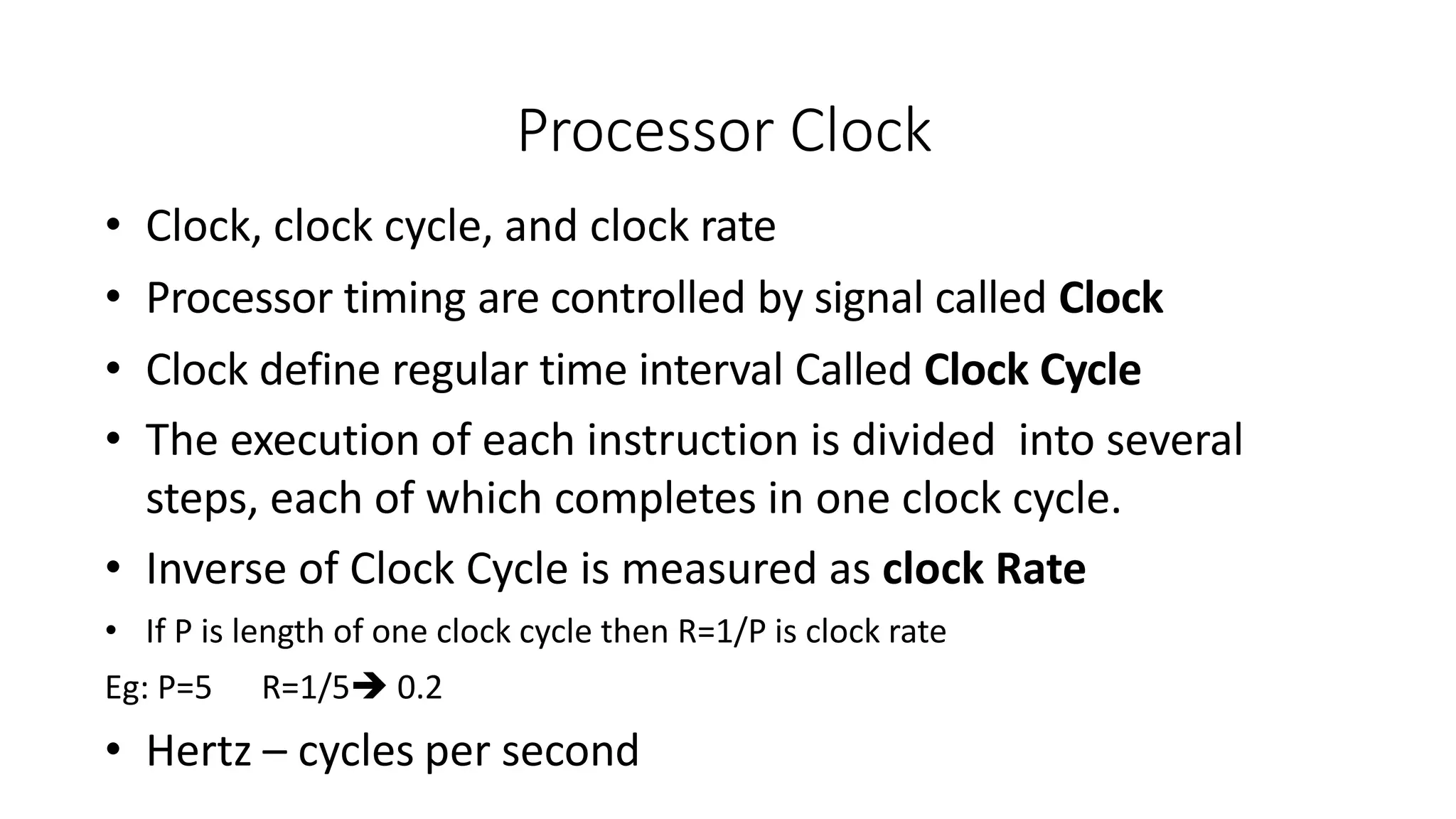
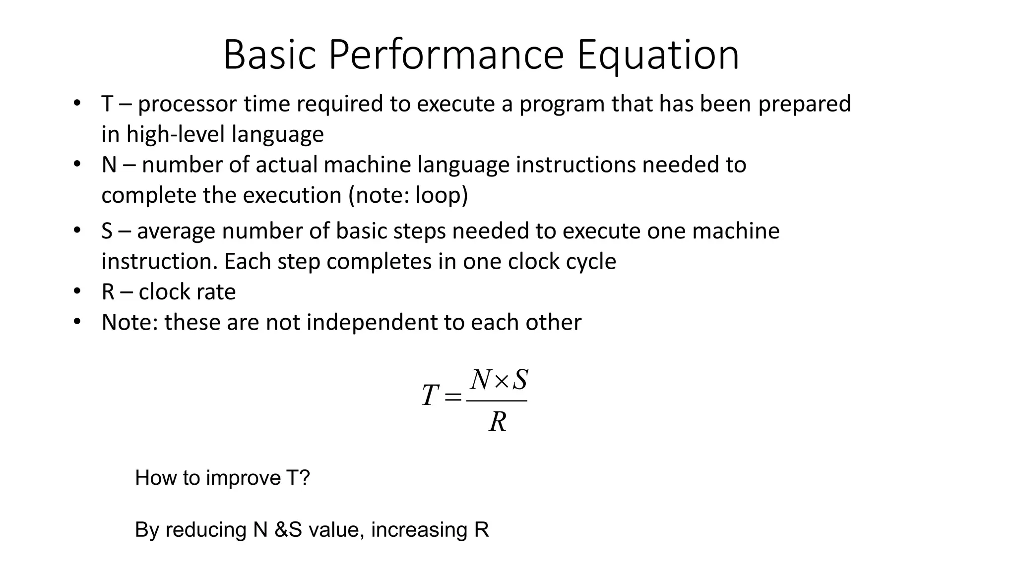
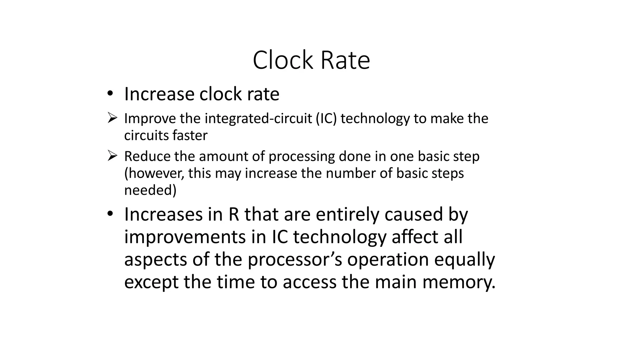
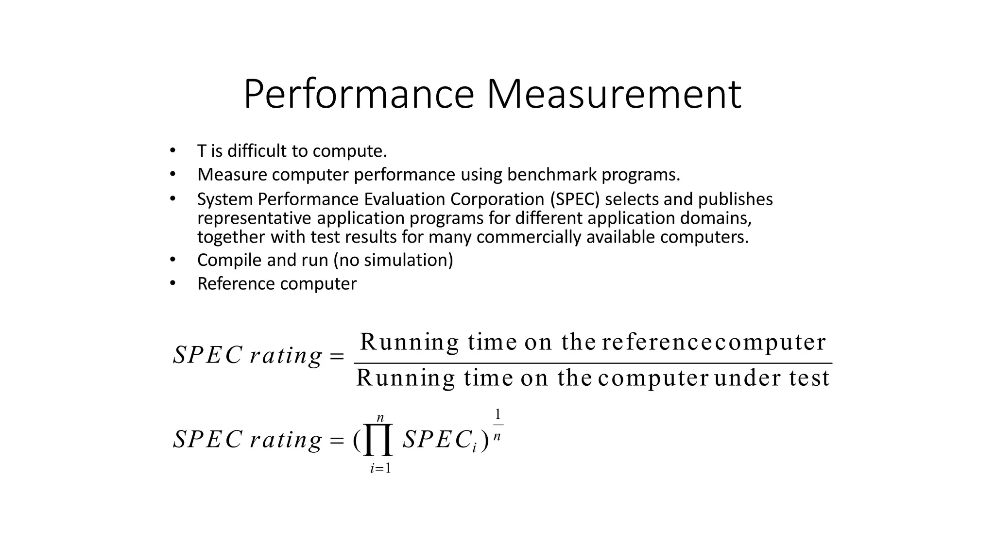
- Performance is a key measure of computers and depends on factors like hardware design, instruction set, and compiler optimizations. Processor clock rate and the basic performance equation are discussed as measures of a computer's


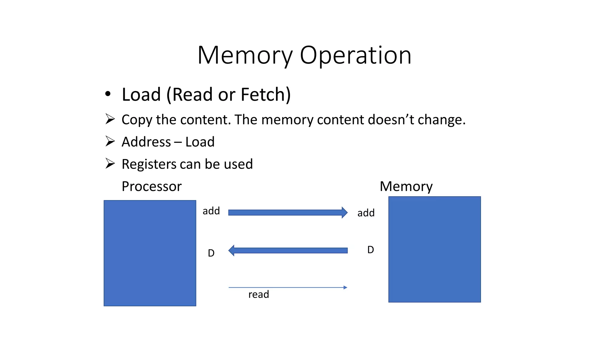
![Register Transfer Notation
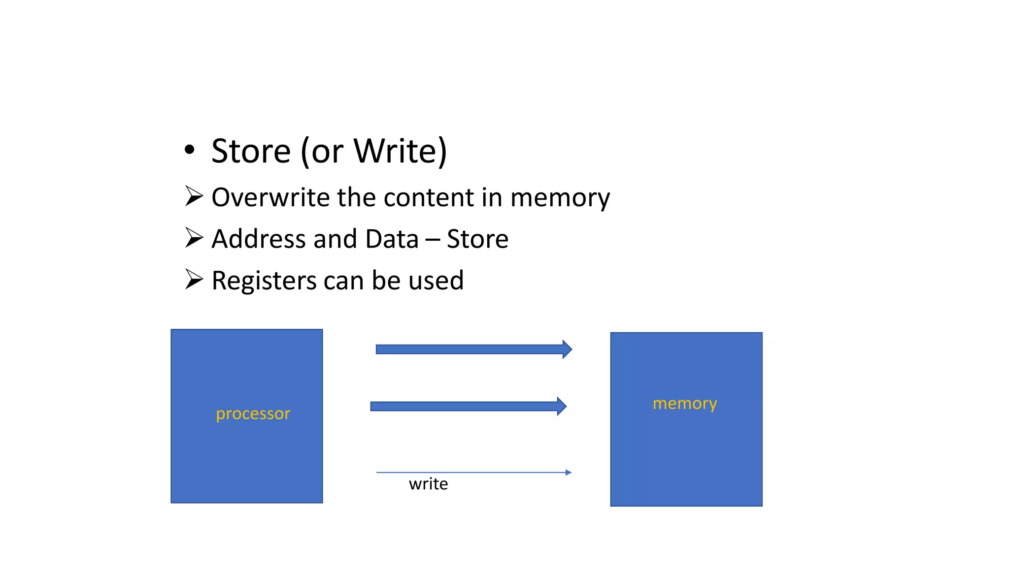
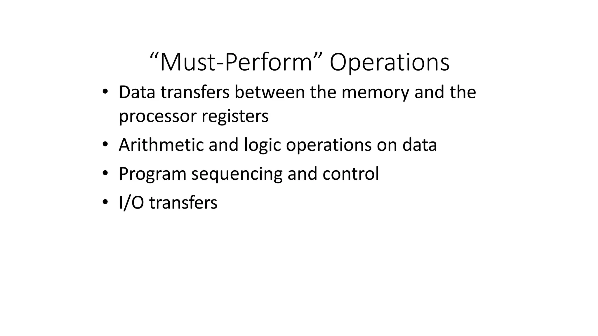
• Data transfer can be represented by using some
notation
LOC,VAR2, PLACE, MEMmemory location
A,…R0,…….Rn,... processor registers
DATAIN,OUTSTATUS,DATAOUT I/O registers
• Contents of a location are denoted by placing square
brackets around the name of the location
Eg: 1. R1←[LOC]
Eg: 2 . R3 ← [R1]+[ R2]
Register Transfer Notation (RTN)
• Data transfer from right to left](https://image.slidesharecdn.com/introductioncoam1-230215154538-4ca40209/75/introduction-COA-M1-pptx-58-2048.jpg)
![Assembly Language Notation
• Another type of notation used to represent
instruction
• Register name memory location are same as that of
RTN
• Represent machine instructions and programs.
Move LOC, R1 = R1←[LOC]
Add R1, R2, R3 = R3 ←[R1]+[R2]
Operation Source Destination
• Most of the computer follow this left to right
assignment
• Divided in to 3 fields](https://image.slidesharecdn.com/introductioncoam1-230215154538-4ca40209/75/introduction-COA-M1-pptx-59-2048.jpg)
![Instruction Formats
• Three-Address Instructions
• If n –bit is required to specify one memory address then 3n-
bit required to specify 3 address instruction
Operation Source1, Source2, Destination
ADD A, B, C
Cannot fit complete instruction in one word for 32bit
computer
• Two-Address Instructions
Operation Source, Destination
ADD A,B i.e., [B] [A]+[B] B is both Source and Destination
Opcode Operand(s) or Address(es)](https://image.slidesharecdn.com/introductioncoam1-230215154538-4ca40209/75/introduction-COA-M1-pptx-62-2048.jpg)
![Move B,C C [B]
Add A,C C [A]+[C]
Together can
perform
Add A,B,C
TwoAddress instruction containing two memory locations
also cannot fit into one word. Therefore a processor
register called accumulator can be used in One Address
instructions.
One-Address Instructions
Add A, B, C can be accomplished using below set
Load A
Add B
Store C
AC [A]
AC [AC] + [B]
C [AC]](https://image.slidesharecdn.com/introductioncoam1-230215154538-4ca40209/75/introduction-COA-M1-pptx-63-2048.jpg)
![Instruction Formats
Example: Evaluate (A+B) (C+D)
• Three-Address
1. ADD A, B, R1
2. ADD C, D, R2
3. MUL R1, R2, X
; R1 ← M[A] + M[B]
; R2 ← M[C] + M[D]
; M[X] ← [R1] [R2]](https://image.slidesharecdn.com/introductioncoam1-230215154538-4ca40209/75/introduction-COA-M1-pptx-66-2048.jpg)
![Instruction Formats
Example: Evaluate (A+B) (C+D)
• Two-Address
1. MOV A, R1
2. ADD B, R1
3. MOV C, R2
4. ADD D, R2
5. MUL R2, R1
6. MOV R1, X
; R1 ← M[A]
; R1 ← [R1] + M[B]
; R2 ← M[C]
; R2 ← [R2] + M[D]
; R1 ← [R1] [R2]
; M[X] ← [R1]](https://image.slidesharecdn.com/introductioncoam1-230215154538-4ca40209/75/introduction-COA-M1-pptx-67-2048.jpg)
![Instruction Formats
Example: Evaluate (A+B) (C+D)
• One-Address
1. LOAD A
2. ADD B
3. STORE T
4. LOAD C
5. ADD D
6. MUL T
7. STORE X
; AC ← M[A]
; AC ← [AC] + M[B]
; M[T] ← [AC]
; AC ← M[C]
; AC ← [AC] + M[D]
; AC ← [AC] M[T]
; M[X] ← [AC]](https://image.slidesharecdn.com/introductioncoam1-230215154538-4ca40209/75/introduction-COA-M1-pptx-68-2048.jpg)
![Instruction Formats
• PUSH A TOS A
• PUSH B TOS B
• ADD TOS(A+B)
• PUSH C TOS C
• PUSH D TOSD
• ADD TOS(C+D)
• MUL TOS (C+D) * (A+B)
• POP X M[X] TOS
• Eg2: X=A*B+C*D
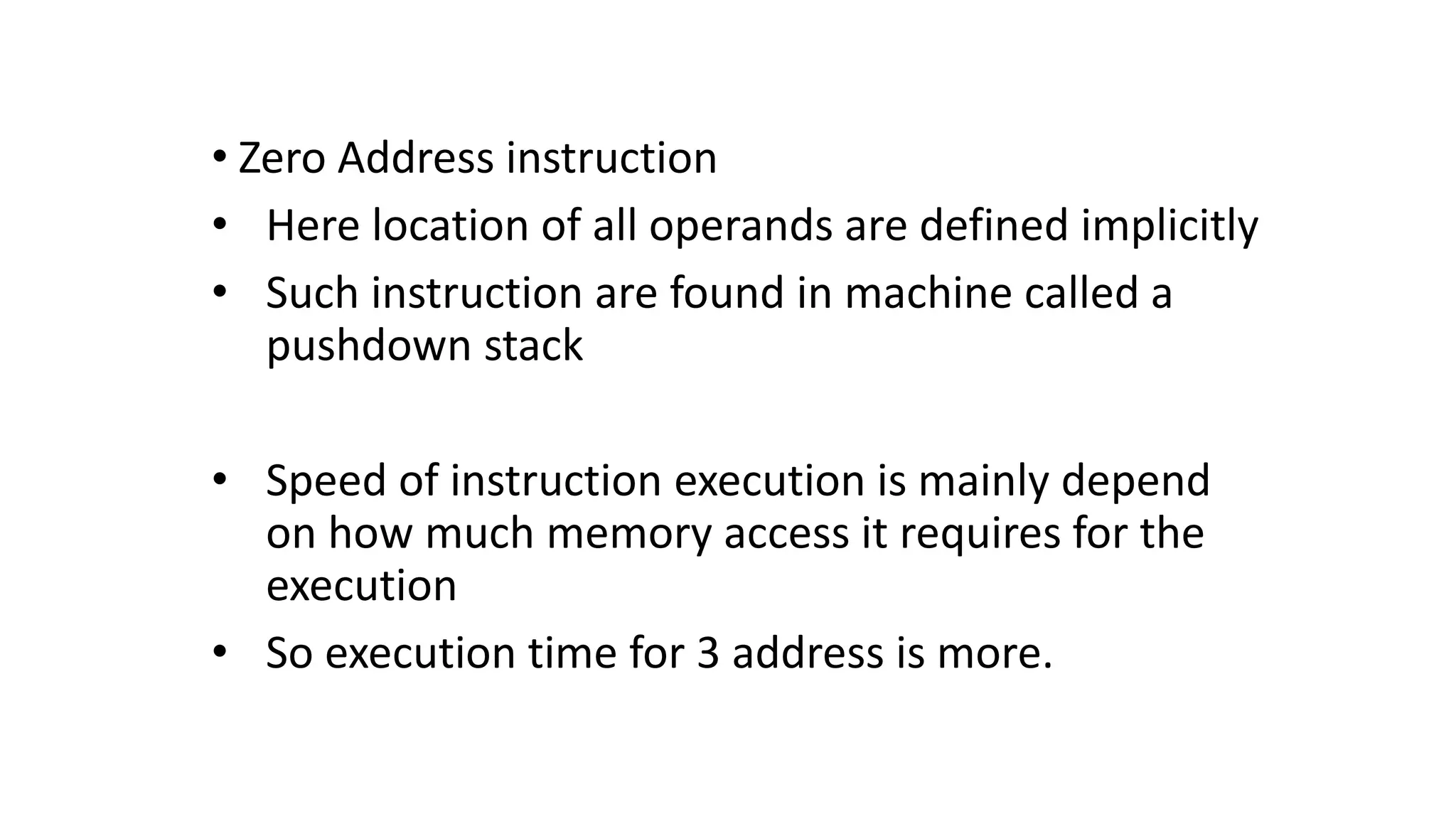
Zero address instruction](https://image.slidesharecdn.com/introductioncoam1-230215154538-4ca40209/75/introduction-COA-M1-pptx-69-2048.jpg)
![NUMn
Figure 2.9. A straight-line program for adding n
numbers.
SUM
NUM1
NUM2
i + 4n- 4
i + 4n
i
i + 4
i + 8
Move NUM1,R0
Add NUM2,R0
Add NUM3,R0
•
•
•
Add NUMn,R0
Move R0,SUM
•
•
•
•
•
•
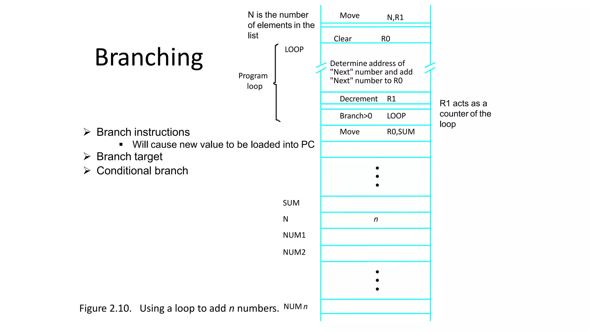
Branching
Add a list of n numbers
for( i=0; i<n; i++ )
sum= sum + a[i];
No of code is more
1
2
3](https://image.slidesharecdn.com/introductioncoam1-230215154538-4ca40209/75/introduction-COA-M1-pptx-74-2048.jpg)
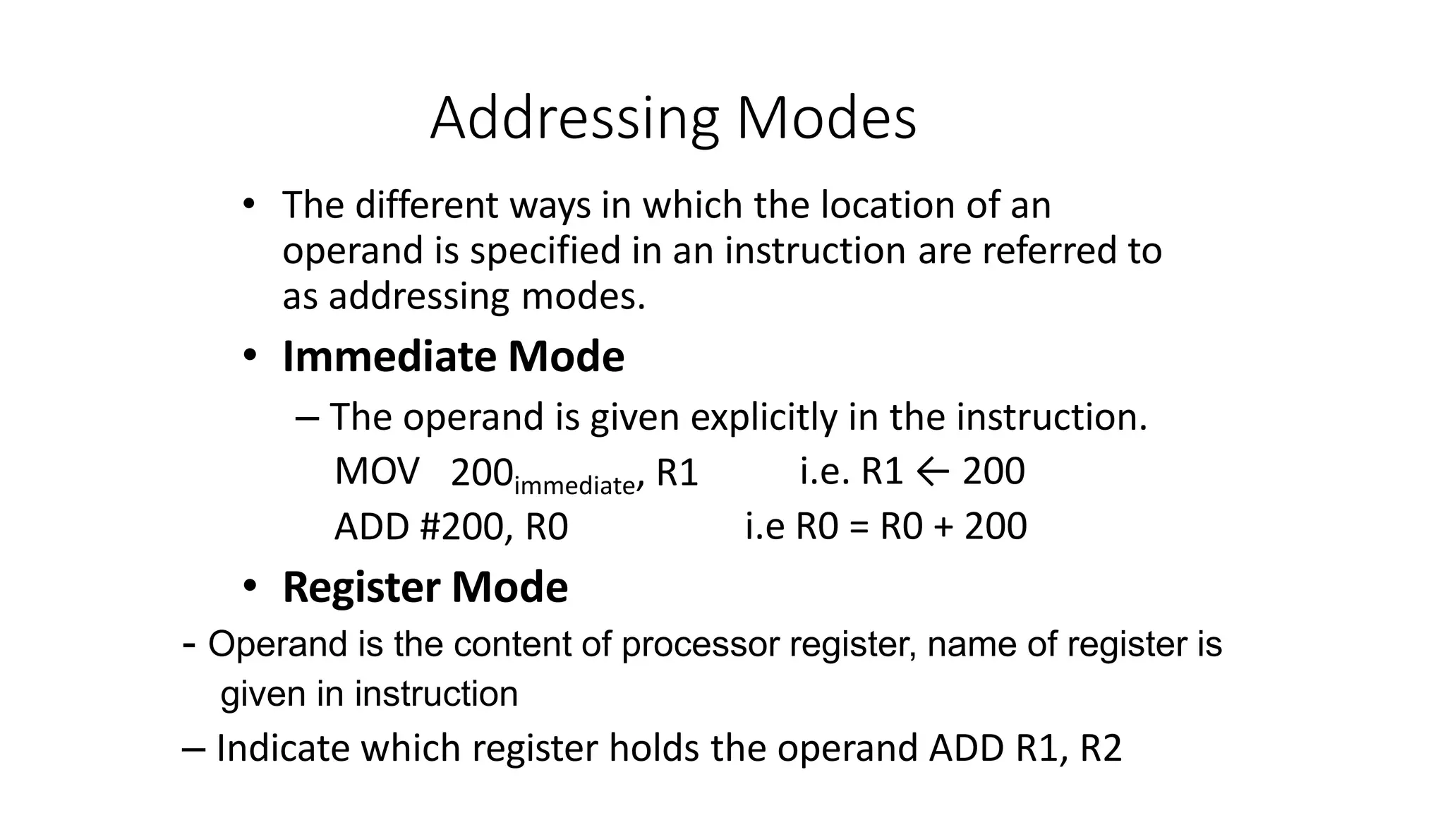
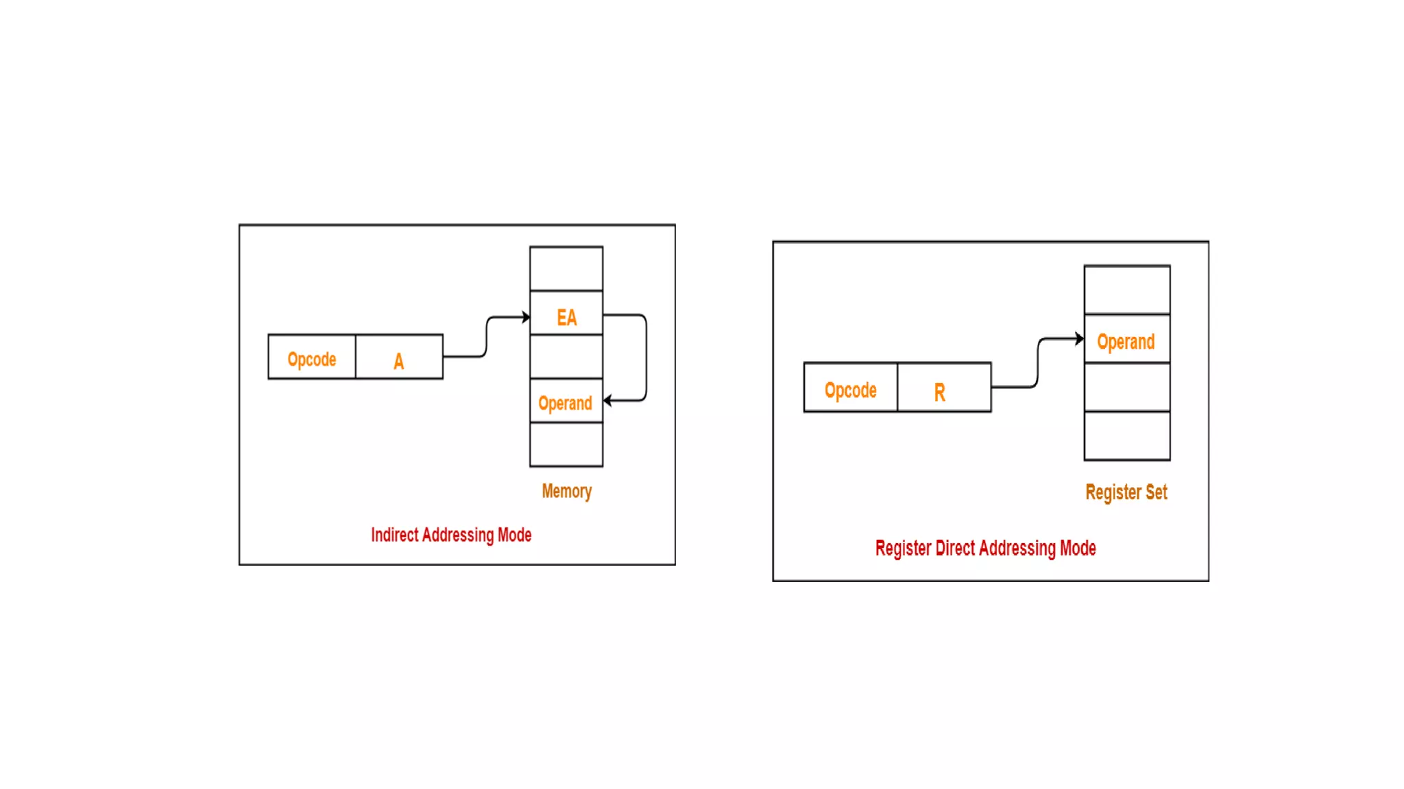
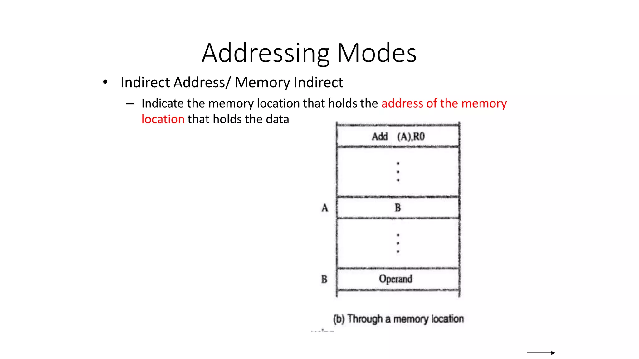
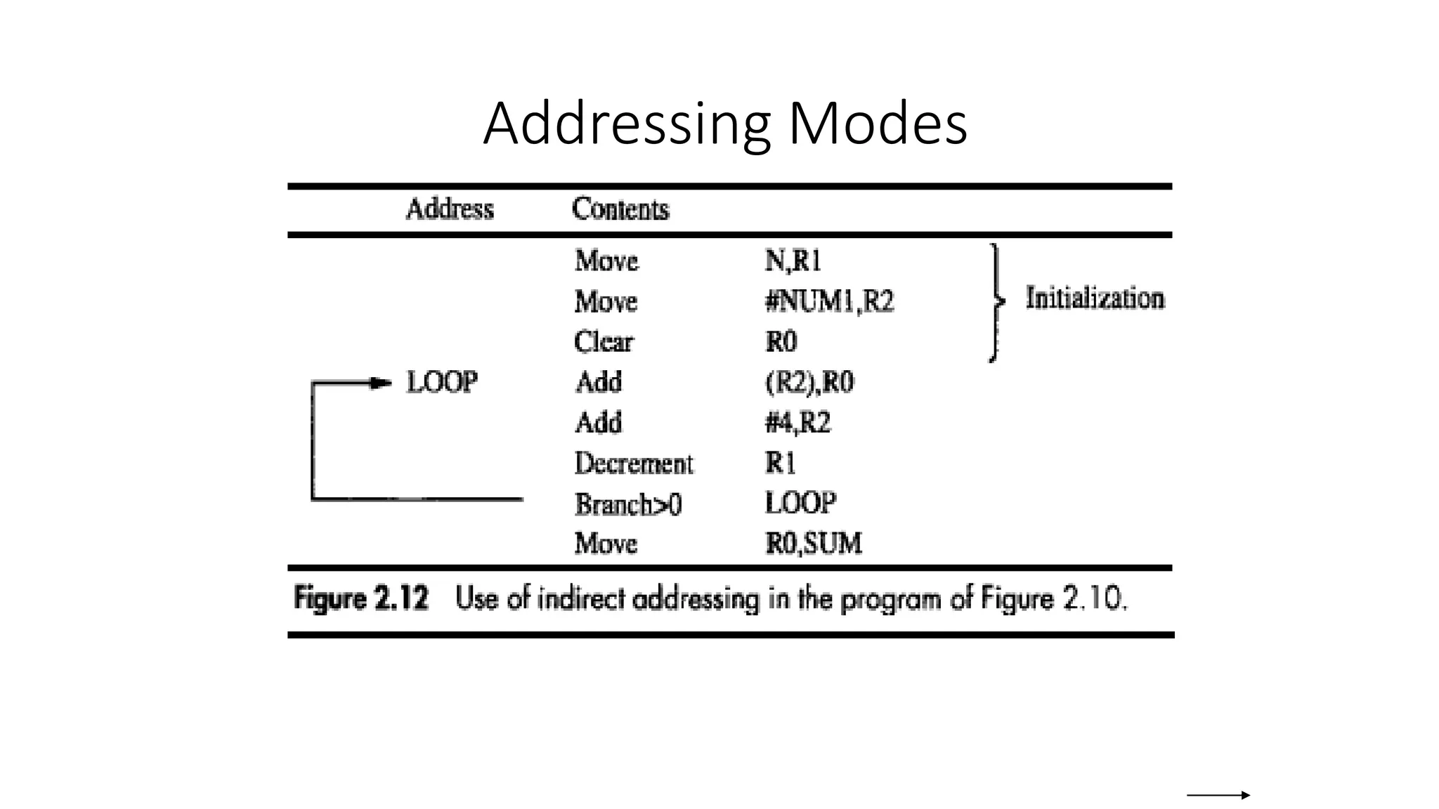
![Addressing Modes
• The different
ways in which
the location of
an operand is
specified in an
instruction are
referred to as
addressing
modes.
Name Assem bler syn tax Addressing function
Immediate #Value Op erand = Value
Register R i EA = R i
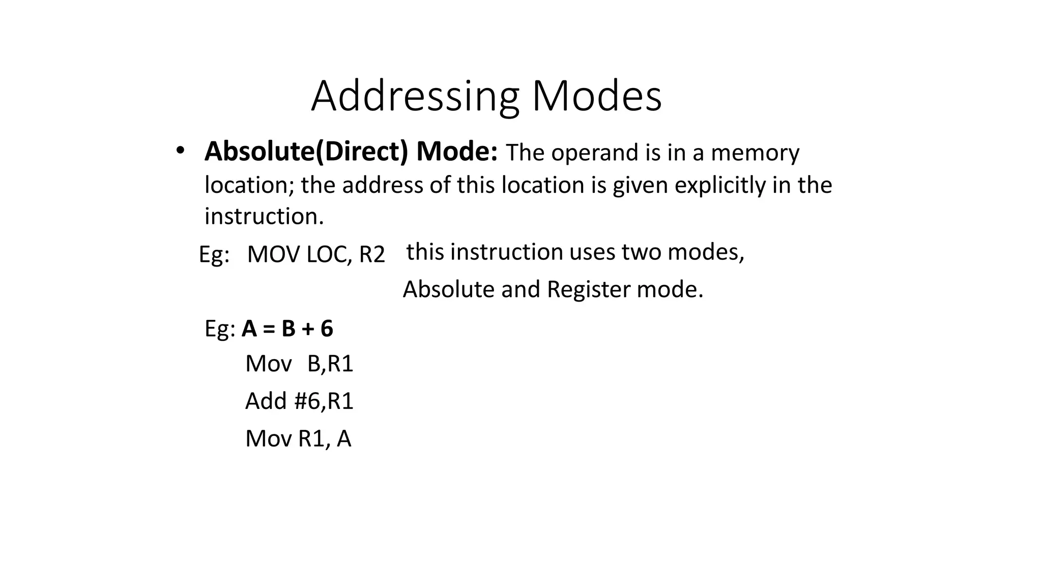
Absolute (Direct) LOC EA = LOC
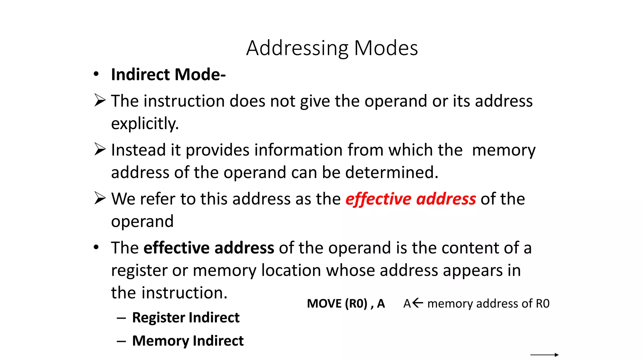
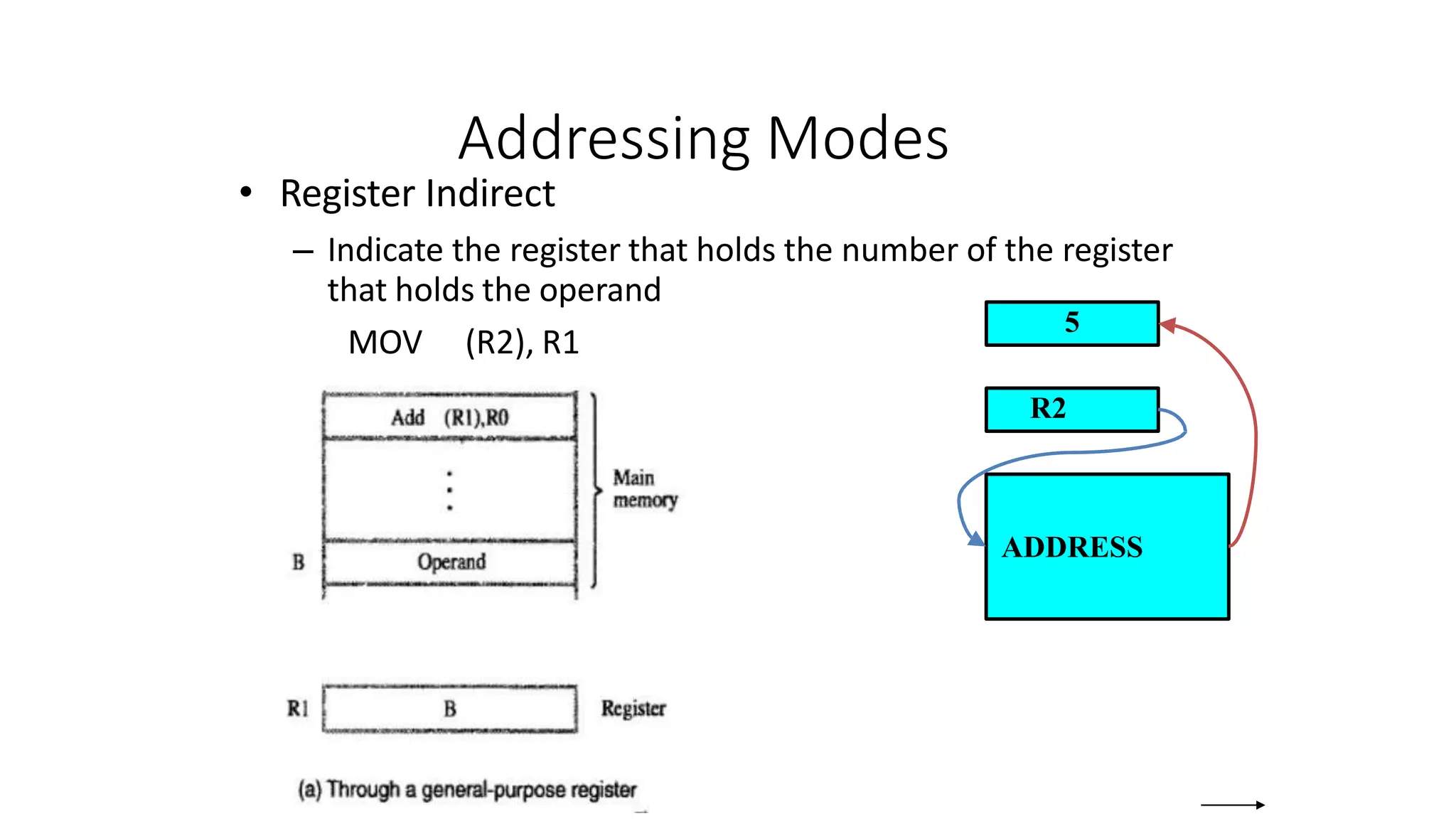
Indirect (R i ) EA = [R i ]
(LOC) EA = [LOC]
Index X(R i) EA = [R i ] + X
Base with index (R i ,R j ) EA = [R i ] + [R j ]
Base with index X(R i,R j ) EA = [R i ] + [R j ] + X
and offset
Relative X(PC) EA = [PC] + X
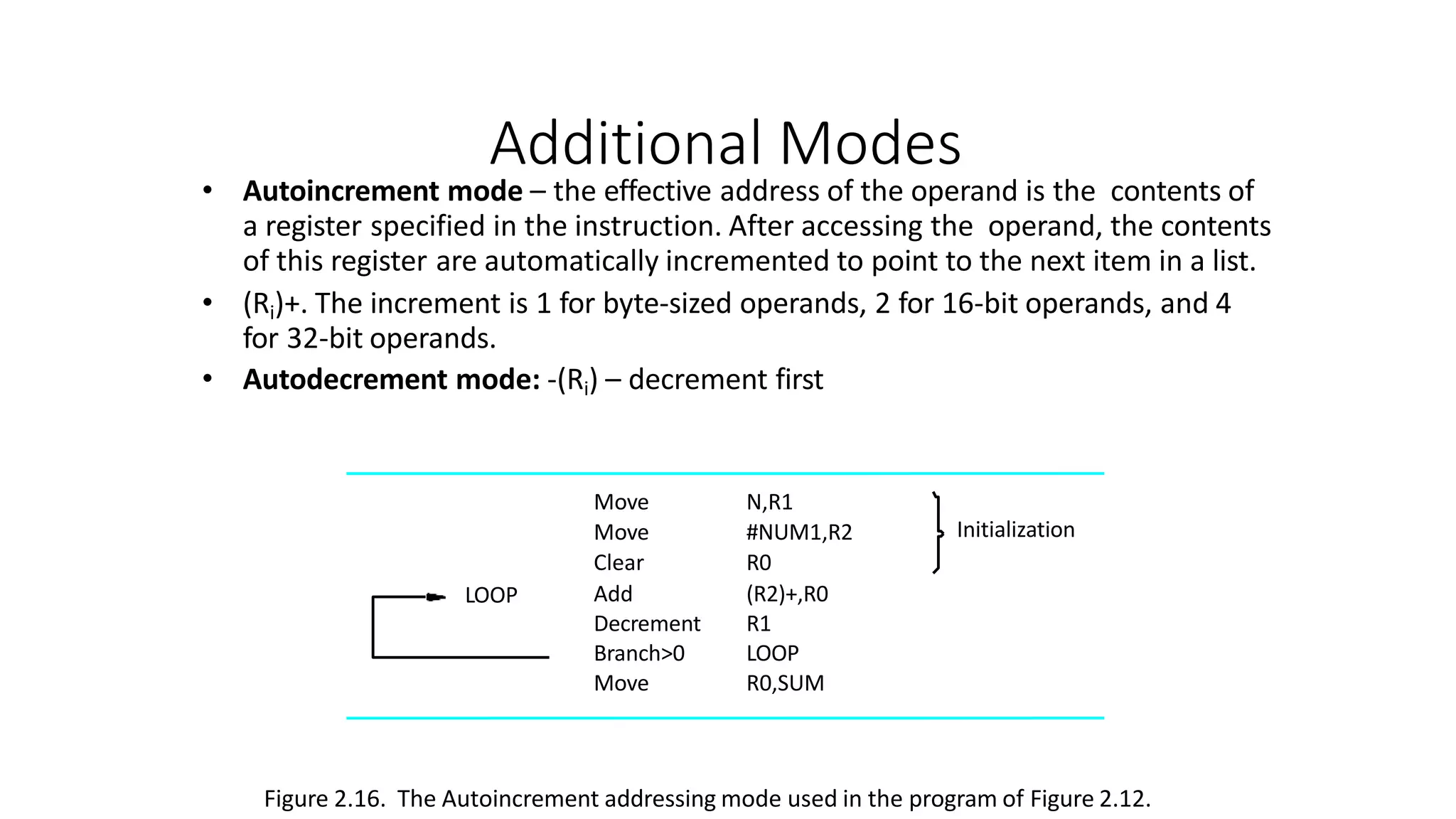
Autoincremen t (R i )+ EA = [R i ] ;
Incremen t R i
Autodecrement Decremen t R i ;
EA = [R i]
(R i )](https://image.slidesharecdn.com/introductioncoam1-230215154538-4ca40209/75/introduction-COA-M1-pptx-86-2048.jpg)
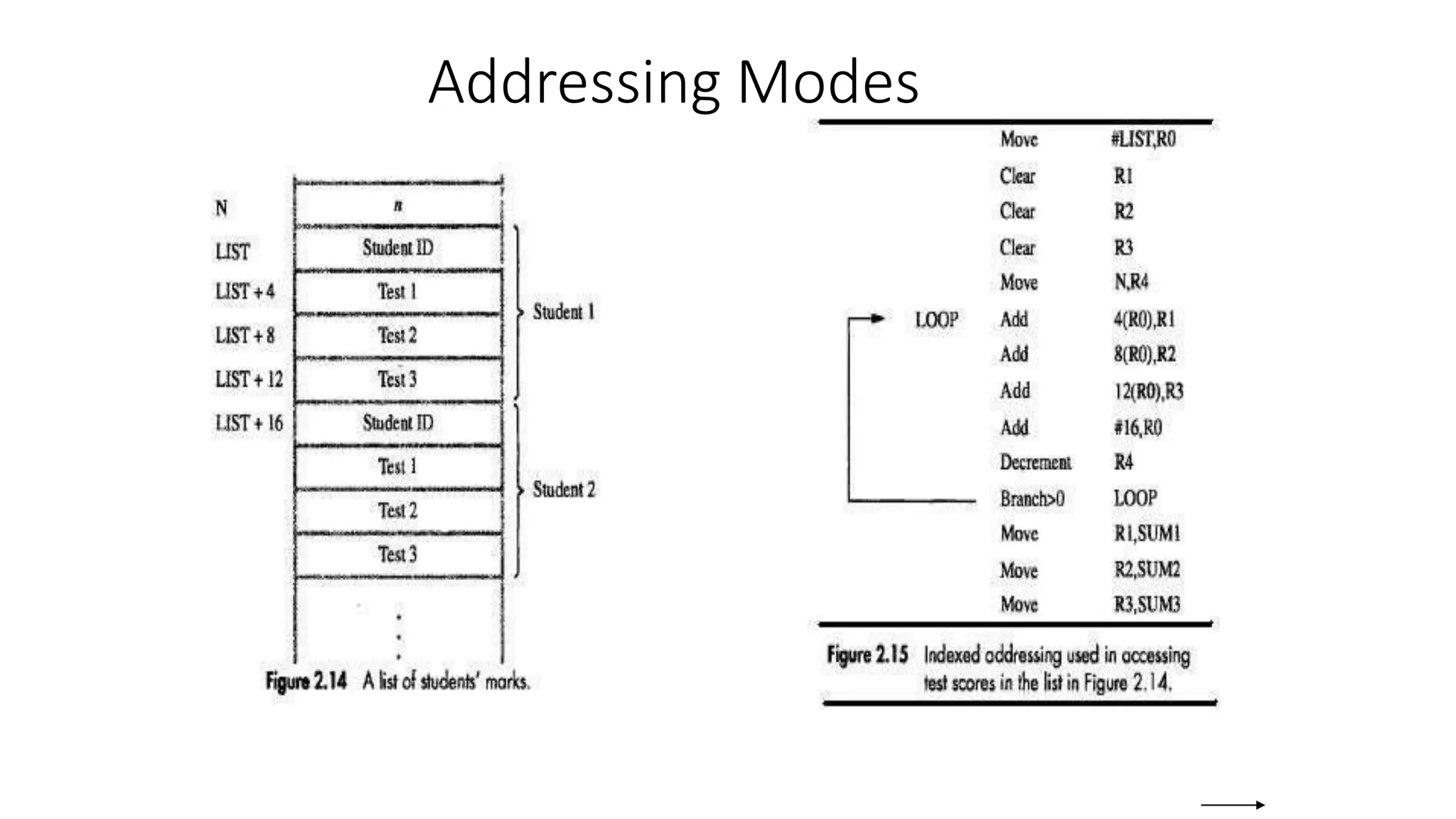
![Indexing
• Index mode – the effective address of the operand is
generated by adding a constant value to the contents of a
register.
• Index register
• X(Ri)
– EA = X + [Ri]
• The constant X may be given either as an explicit number or
as a symbolic name representing a numerical value.](https://image.slidesharecdn.com/introductioncoam1-230215154538-4ca40209/75/introduction-COA-M1-pptx-87-2048.jpg)
![Indexing
• In general, the Index mode facilitates access to an
operand whose location is defined relative to a
reference point called offset
• Several variations:
• base indexing
(Ri,Rj): EA = [Ri] + [Rj]
• base and offset with
offset
X(Ri, Rj): EA = X + [Ri] + [Rj]](https://image.slidesharecdn.com/introductioncoam1-230215154538-4ca40209/75/introduction-COA-M1-pptx-88-2048.jpg)