Downloaded 137 times
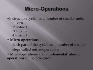
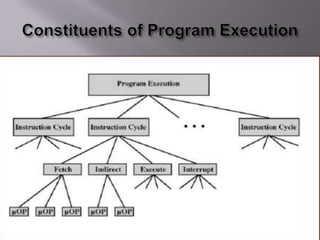

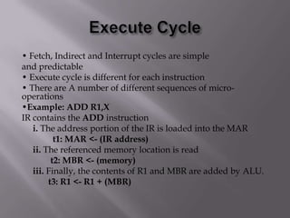

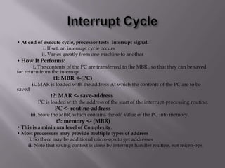
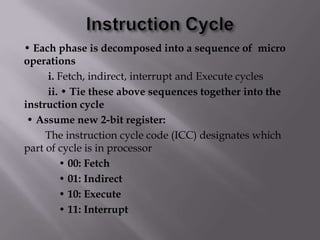
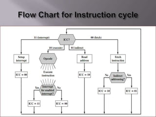
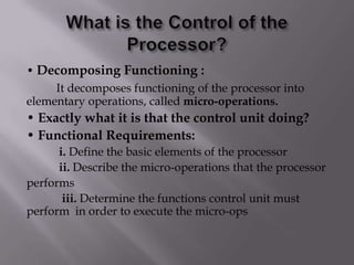
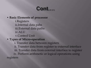
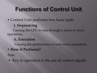
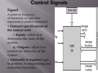
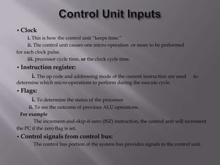
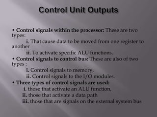


The document decomposes the functioning of a processor into elementary operations called micro-operations. It describes the basic elements of a processor including registers, data paths, an ALU, and a control unit. The control unit sequences and executes micro-operations to perform the fetch, indirect, execute, and interrupt cycles of the instruction cycle. The control unit uses a clock, instruction register, and flags to determine the timing and sequencing of micro-operations.