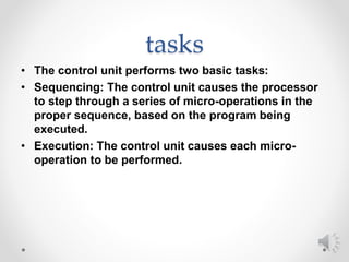
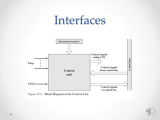
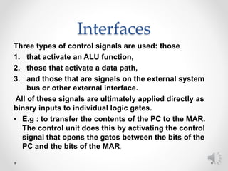
CPU
CONTROL UNIT
CONTROL UNIT
• KEY POINTS
• The execution of an instruction involves the
execution of a sequence of substeps, generally
called cycles. For example, an execution may
consist of fetch, execute, and interrupt cycles. Each
cycle is in turn made up of a sequence of more
fundamental operations, called micro-operations. A
single micro-operation generally involves a transfer
between registers, a transfe between a register and
an external bus, or a simple ALU operation.
CONTROL UNIT
• KEY POINTS
• The control unit of a processor performs two tasks:
(1) It causes the processor to ste through a series of
micro-operations in the proper sequence, based on
the program being executed, and (2) it generates the
contro signals that cause each micro-operation to be
executed.
CONTROL UNIT
• KEY POINTS
• The control signals generated by the control unit
cause the opening and closing of logic gates,
resulting in the transfer of data to and from registers
and the operation of the ALU.
• each of the smaller cycles involves a series of steps,
each of which involves the processor registers. We
will refer to these steps as micro-operations.
The Fetch Cycle
• Four registers are involved:
1. Memory address register (MAR): Is connected to
the address lines of the system bus. It specifies the
address in memory for a read or write operation.
2. • Memory buffer register (MBR): Is connected to the
data lines of the system bus. It contains the value
to be stored in memory or the last value read from
memory.
3. • Program counter (PC): Holds the address of the
next instruction to be fetched.
4. • Instruction register (IR): Holds the last instruction
fetched
The Fetch Cycle
• Steps
1. the address of the next instruction to be executed is in the
program counter (PC);
2. move that address to the memory address register (MAR)
3. bring in the instruction:The desired address (in the MAR) is
placed on the address bus, the control unit issues a READ
command on the control bus, and the result appears on the
data bus and is copied into the memory buffer register (MBR)
4. increment the PC by the instruction length to get ready for the
next instruction.(Because these two actions (read word from
memory, increment PC) do not interfere with each other, we
can do them simultaneously to save time.)
5. move the contents of the MBR to the instruction register (IR).
The Fetch Cycle
The Execute Cycle
• there are a number of different sequences of micro-
operations that can occur , due to the variety opcodes.
• ADD R1, X
• t1: MAR ← (IR(address))
• t2: MBR ← Memory
• t3: R1 ← (R1) + (MBR)
micro-operations
• micro-operations fall in to one of the following
categories:
1. Transfer data from one register to another.
2. Transfer data from a register to an external
interface (e.g., system bus).
3. Transfer data from an external interface to a
register.
4. Perform an arithmetic or logic operation, using
registers for input and output
tasks
• The control unit performs two basic tasks:
• Sequencing: The control unit causes the processor
to step through a series of micro-operations in the
proper sequence, based on the program being
executed.
• Execution: The control unit causes each micro-
operation to be performed.
Interfaces
Interfaces
Three types of control signals are used: those
1. that activate an ALU function,
2. those that activate a data path,
3. and those that are signals on the external system
bus or other external interface.
All of these signals are ultimately applied directly as
binary inputs to individual logic gates.
• E.g : to transfer the contents of the PC to the MAR.
The control unit does this by activating the control
signal that opens the gates between the bits of the
PC and the bits of the MAR.
HARDWIRED
IMPLEMENTATION
HARDWIRED
IMPLEMENTATION
• To simplify the control unit logic, there should be a
unique logic input for each opcode This function can
be performed by a decoder, which takes an encoded
input and produces a single output.
• Timing Generator: generate timing signal consist of
counter and decoder ,with pulse there is single
timing signal.
HARDWIRED
IMPLEMENTATION
• Consider I0 required the following sequence of
control signal
• C7 = t2  I0 C3 = t1  I0
HARDWIRED
IMPLEMENTATION
• Consider I9 required the following sequence of
control signal
HARDWIRED
IMPLEMENTATION
CISC & RISC
• Complex instruction set computers (CISC)
o These machines provided a variety of
instructions that may perform very
complex tasks
o To ease task for programmers
o Use large numbers of addressing modes
o Require many clock cycles per instruction
o Used a number of different instruction
formats of varying lengths
CISC & RISC
• Reduced instruction set computers (RISC)
o Fewer and simpler instructions
o Few instruction formats
o Few cycle per instruction
o Large number of internal CPU registers
o Best suited with pipeline processors

Control unit

  • 1.
  • 2.
    CONTROL UNIT • KEYPOINTS • The execution of an instruction involves the execution of a sequence of substeps, generally called cycles. For example, an execution may consist of fetch, execute, and interrupt cycles. Each cycle is in turn made up of a sequence of more fundamental operations, called micro-operations. A single micro-operation generally involves a transfer between registers, a transfe between a register and an external bus, or a simple ALU operation.
  • 3.
    CONTROL UNIT • KEYPOINTS • The control unit of a processor performs two tasks: (1) It causes the processor to ste through a series of micro-operations in the proper sequence, based on the program being executed, and (2) it generates the contro signals that cause each micro-operation to be executed.
  • 4.
    CONTROL UNIT • KEYPOINTS • The control signals generated by the control unit cause the opening and closing of logic gates, resulting in the transfer of data to and from registers and the operation of the ALU. • each of the smaller cycles involves a series of steps, each of which involves the processor registers. We will refer to these steps as micro-operations.
  • 5.
    The Fetch Cycle •Four registers are involved: 1. Memory address register (MAR): Is connected to the address lines of the system bus. It specifies the address in memory for a read or write operation. 2. • Memory buffer register (MBR): Is connected to the data lines of the system bus. It contains the value to be stored in memory or the last value read from memory. 3. • Program counter (PC): Holds the address of the next instruction to be fetched. 4. • Instruction register (IR): Holds the last instruction fetched
  • 6.
    The Fetch Cycle •Steps 1. the address of the next instruction to be executed is in the program counter (PC); 2. move that address to the memory address register (MAR) 3. bring in the instruction:The desired address (in the MAR) is placed on the address bus, the control unit issues a READ command on the control bus, and the result appears on the data bus and is copied into the memory buffer register (MBR) 4. increment the PC by the instruction length to get ready for the next instruction.(Because these two actions (read word from memory, increment PC) do not interfere with each other, we can do them simultaneously to save time.) 5. move the contents of the MBR to the instruction register (IR).
  • 7.
  • 8.
    The Execute Cycle •there are a number of different sequences of micro- operations that can occur , due to the variety opcodes. • ADD R1, X • t1: MAR ← (IR(address)) • t2: MBR ← Memory • t3: R1 ← (R1) + (MBR)
  • 9.
    micro-operations • micro-operations fallin to one of the following categories: 1. Transfer data from one register to another. 2. Transfer data from a register to an external interface (e.g., system bus). 3. Transfer data from an external interface to a register. 4. Perform an arithmetic or logic operation, using registers for input and output
  • 10.
    tasks • The controlunit performs two basic tasks: • Sequencing: The control unit causes the processor to step through a series of micro-operations in the proper sequence, based on the program being executed. • Execution: The control unit causes each micro- operation to be performed.
  • 11.
  • 12.
    Interfaces Three types ofcontrol signals are used: those 1. that activate an ALU function, 2. those that activate a data path, 3. and those that are signals on the external system bus or other external interface. All of these signals are ultimately applied directly as binary inputs to individual logic gates. • E.g : to transfer the contents of the PC to the MAR. The control unit does this by activating the control signal that opens the gates between the bits of the PC and the bits of the MAR.
  • 13.
  • 14.
    HARDWIRED IMPLEMENTATION • To simplifythe control unit logic, there should be a unique logic input for each opcode This function can be performed by a decoder, which takes an encoded input and produces a single output. • Timing Generator: generate timing signal consist of counter and decoder ,with pulse there is single timing signal.
  • 15.
    HARDWIRED IMPLEMENTATION • Consider I0required the following sequence of control signal • C7 = t2  I0 C3 = t1  I0
  • 16.
    HARDWIRED IMPLEMENTATION • Consider I9required the following sequence of control signal
  • 17.
  • 18.
    CISC & RISC •Complex instruction set computers (CISC) o These machines provided a variety of instructions that may perform very complex tasks o To ease task for programmers o Use large numbers of addressing modes o Require many clock cycles per instruction o Used a number of different instruction formats of varying lengths
  • 19.
    CISC & RISC •Reduced instruction set computers (RISC) o Fewer and simpler instructions o Few instruction formats o Few cycle per instruction o Large number of internal CPU registers o Best suited with pipeline processors