Downloaded 120 times

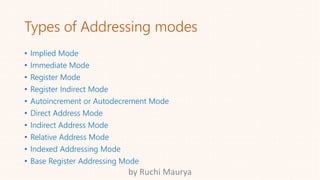
![Types of Instruction Format
• Three address instruction
• ADD R1, A, B //R1<-M[A]+M[B]
• Two address instruction
• MOV R1, A //R1<-M[A]
• One address instruction
• LOAD A //AC<-M[A]
• Zero address instruction
• PUSH A //TOS<-A
by Ruchi Maurya](https://image.slidesharecdn.com/coaslideshare-160809132440/85/Types-of-Addressing-modes-COA-9-320.jpg)
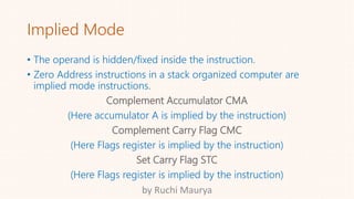
![Register Indirect Mode
• The instruction specifies the register in which the memory address
of operand is placed.
• It do not specify the operand itself but its location with in the
memory where operand is placed.
Move
MOV A , M A ← [[H][L]]
It moves the data from memory location specified by HL register
pair to A.
by Ruchi Maurya](https://image.slidesharecdn.com/coaslideshare-160809132440/85/Types-of-Addressing-modes-COA-15-320.jpg)
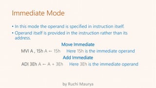
![Direct Addressing Mode
• The instruction specifies the direct address of the operand.
• The memory address is specified where the actual operand is.
Load Accumulator
LDA 2805h A ← [2805]
It loads the data from memory location 2805 to A.
Store Accumulator
STA2803h [2803] ← A
It stores the data from A to memory location 2803.
by Ruchi Maurya](https://image.slidesharecdn.com/coaslideshare-160809132440/85/Types-of-Addressing-modes-COA-16-320.jpg)


The document provides an overview of computer organization and architecture, focusing on stack organizations, instruction formats, and addressing modes. It explains stack operations such as push and pop, details various types of instruction formats, and describes multiple addressing modes used to access operands during program execution. Key examples include the differentiation between immediate, register, and direct addressing modes, along with their respective operations.