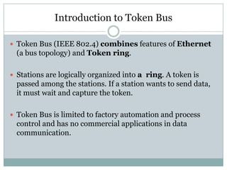
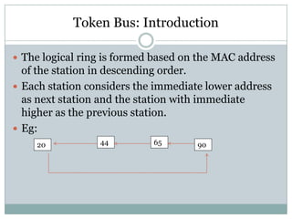
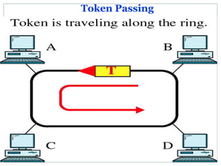
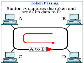
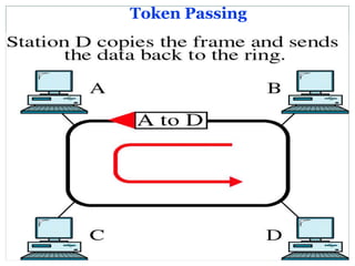
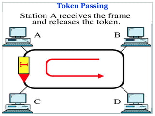
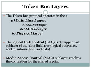
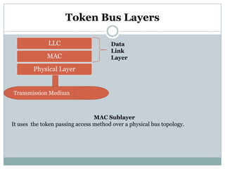
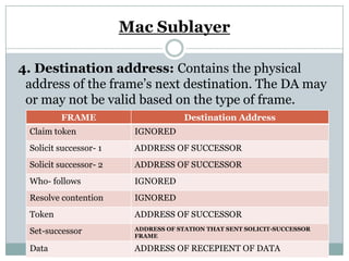
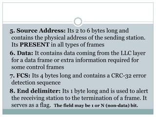
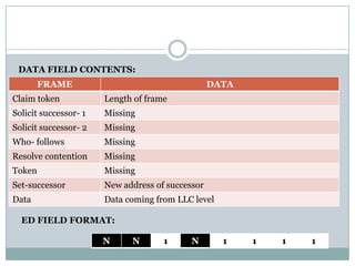
Token Bus (IEEE 802.4) : Definition


 Token bus is a physical bus
 that operates as a logical ring
 using tokens.
    (From: Local Area Networks - Fourzan)
Introduction to Token Bus

 Token Bus (IEEE 802.4) combines features of Ethernet
  (a bus topology) and Token ring.

 Stations are logically organized into a ring. A token is
  passed among the stations. If a station wants to send data,
  it must wait and capture the token.

 Token Bus is limited to factory automation and process
  control and has no commercial applications in data
  communication.
Token Bus: Introduction

 The logical ring is formed based on the MAC address
  of the station in descending order.
 Each station considers the immediate lower address
  as next station and the station with immediate
  higher as the previous station.
 Eg:
    20           44         65       90
Token Ring (IEEE 802.5)

 Token ring requires that stations take turns sending data.


 Each station may transmit only during its turn and may
  send only one frame during each turn.

 The mechanism that coordinates this rotation is called
  token passing.
Token Passing
Token Passing
Token Passing
Token Passing
Service Classes
Service Classes
Ring Management
Ring Management: Removing Stations

        1. Voluntary Leaving:
Ring Management: Removing Stations

       2. Unexpected Leaving:
Ring Management: Adding Stations

 CASE 1
Ring Management: Adding Stations

 CASE 1 (Contd….)
Ring Management: Adding Stations

 CASE 2
Ring Management

  Token Recovery
Ring Management

 Removing Duplicate Tokens
Ring Management

 Ring Initialization
Token Bus Layers
 The Token Bus protocol operates in the :-
     a) Data Link Layer:
            1. LLC Sublayer
           2. MAC Sublayer
     b) Physical Layer

 The logical link control (LLC) is the upper part
 sublayer of the data link layer (logical addresses,
 control information, and data)

 Media Access Control (MAC) sublayer resolves
 the contention for the shared media.
Token Bus Layers

              LLC                      Data
                                       Link
              MAC                      Layer

        Physical Layer


Transmission Medium


                                 MAC Sublayer
It uses the token passing access method over a physical bus topology.
Mac Sublayer

 Frame Format – general format of fields in the frame at
 the MAC layer
  1. Preamble: Consists of one or more bytes of a
  pre-defined pattern to synchronize the sender and
  receiver.
 2. Start delimiter: Its 1 byte long and is used to
  alert the receiving station when a frame is arriving.
 3. Frame control: Its 1 byte long and defines the
  type of the frame: if the 1st 2 bits are 00 - MAC control frame
                  if 01 – data frame from LLC layer.
                  if 10 – Data from other protocols.
Mac Sublayer (Frame Control Field)

 A MAC control frame can be:
        000000 – Claim token
        000001 – Solicit successor- 1
        000010 – Solicit successor- 2
        000011 – Who- follows                FC for
                                             control
        000100 – Resolve contention          frames
        001000 – Token
        001100 – Set-successor
        000 – request – with -no- response
                                              FC for
        001 – request – with response         Data
                                              frames
        010 - response
Mac Sublayer

4. Destination address: Contains the physical
 address of the frame’s next destination. The DA may
 or may not be valid based on the type of frame.
         FRAME                       Destination Address
 Claim token             IGNORED
 Solicit successor- 1    ADDRESS OF SUCCESSOR
 Solicit successor- 2    ADDRESS OF SUCCESSOR
 Who- follows            IGNORED
 Resolve contention      IGNORED
 Token                   ADDRESS OF SUCCESSOR
 Set-successor           ADDRESS OF STATION THAT SENT SOLICIT-SUCCESSOR
                         FRAME

 Data                    ADDRESS OF RECEPIENT OF DATA
5. Source Address: Its 2 to 6 bytes long and
 contains the physical address of the sending station.
 Its PRESENT in all types of frames
6. Data: It contains data coming from the LLC layer
 for a data frame or extra information required for
 some control frames
7. FCS: Its 4 bytes long and contains a CRC-32 error
 detection sequence
8. End delimiter: Its 1 byte long and is used to alert
 the receiving station to the termination of a frame. It
 serves as a flag. The field may be 1 or N (non-data) bit.
DATA FIELD CONTENTS:
        FRAME                                     DATA
Claim token            Length of frame
Solicit successor- 1   Missing
Solicit successor- 2   Missing
Who- follows           Missing
Resolve contention     Missing
Token                  Missing
Set-successor          New address of successor
Data                   Data coming from LLC level

  ED FIELD FORMAT:

                       N     N       1      N       1    1   1   1
Physical Layer

Token bus

  • 1.
    Token Bus (IEEE802.4) : Definition  Token bus is a physical bus that operates as a logical ring using tokens. (From: Local Area Networks - Fourzan)
  • 2.
    Introduction to TokenBus  Token Bus (IEEE 802.4) combines features of Ethernet (a bus topology) and Token ring.  Stations are logically organized into a ring. A token is passed among the stations. If a station wants to send data, it must wait and capture the token.  Token Bus is limited to factory automation and process control and has no commercial applications in data communication.
  • 3.
    Token Bus: Introduction The logical ring is formed based on the MAC address of the station in descending order.  Each station considers the immediate lower address as next station and the station with immediate higher as the previous station.  Eg: 20 44 65 90
  • 4.
    Token Ring (IEEE802.5)  Token ring requires that stations take turns sending data.  Each station may transmit only during its turn and may send only one frame during each turn.  The mechanism that coordinates this rotation is called token passing.
  • 5.
  • 6.
  • 7.
  • 8.
  • 9.
  • 10.
  • 11.
  • 12.
    Ring Management: RemovingStations 1. Voluntary Leaving:
  • 13.
    Ring Management: RemovingStations 2. Unexpected Leaving:
  • 14.
    Ring Management: AddingStations  CASE 1
  • 15.
    Ring Management: AddingStations  CASE 1 (Contd….)
  • 16.
    Ring Management: AddingStations  CASE 2
  • 17.
    Ring Management Token Recovery
  • 18.
  • 19.
  • 20.
    Token Bus Layers The Token Bus protocol operates in the :- a) Data Link Layer: 1. LLC Sublayer 2. MAC Sublayer b) Physical Layer  The logical link control (LLC) is the upper part sublayer of the data link layer (logical addresses, control information, and data)  Media Access Control (MAC) sublayer resolves the contention for the shared media.
  • 21.
    Token Bus Layers LLC Data Link MAC Layer Physical Layer Transmission Medium MAC Sublayer It uses the token passing access method over a physical bus topology.
  • 22.
    Mac Sublayer  FrameFormat – general format of fields in the frame at the MAC layer 1. Preamble: Consists of one or more bytes of a pre-defined pattern to synchronize the sender and receiver. 2. Start delimiter: Its 1 byte long and is used to alert the receiving station when a frame is arriving. 3. Frame control: Its 1 byte long and defines the type of the frame: if the 1st 2 bits are 00 - MAC control frame if 01 – data frame from LLC layer. if 10 – Data from other protocols.
  • 23.
    Mac Sublayer (FrameControl Field)  A MAC control frame can be: 000000 – Claim token 000001 – Solicit successor- 1 000010 – Solicit successor- 2 000011 – Who- follows FC for control 000100 – Resolve contention frames 001000 – Token 001100 – Set-successor 000 – request – with -no- response FC for 001 – request – with response Data frames 010 - response
  • 24.
    Mac Sublayer 4. Destinationaddress: Contains the physical address of the frame’s next destination. The DA may or may not be valid based on the type of frame. FRAME Destination Address Claim token IGNORED Solicit successor- 1 ADDRESS OF SUCCESSOR Solicit successor- 2 ADDRESS OF SUCCESSOR Who- follows IGNORED Resolve contention IGNORED Token ADDRESS OF SUCCESSOR Set-successor ADDRESS OF STATION THAT SENT SOLICIT-SUCCESSOR FRAME Data ADDRESS OF RECEPIENT OF DATA
  • 25.
    5. Source Address:Its 2 to 6 bytes long and contains the physical address of the sending station. Its PRESENT in all types of frames 6. Data: It contains data coming from the LLC layer for a data frame or extra information required for some control frames 7. FCS: Its 4 bytes long and contains a CRC-32 error detection sequence 8. End delimiter: Its 1 byte long and is used to alert the receiving station to the termination of a frame. It serves as a flag. The field may be 1 or N (non-data) bit.
  • 26.
    DATA FIELD CONTENTS: FRAME DATA Claim token Length of frame Solicit successor- 1 Missing Solicit successor- 2 Missing Who- follows Missing Resolve contention Missing Token Missing Set-successor New address of successor Data Data coming from LLC level ED FIELD FORMAT: N N 1 N 1 1 1 1
  • 27.