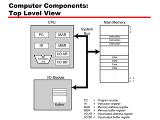
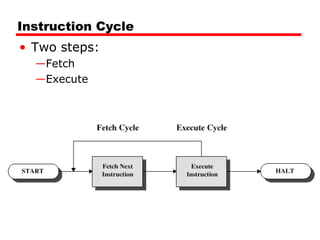
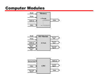
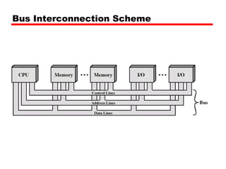
Program Concept Hardwired systems are inflexible General purpose hardware can do different tasks, given correct control signals Instead of re-wiring, supply a new set of control signals
What is a program? A sequence of steps For each step, an arithmetic or logical operation is done For each operation, a different set of control signals is needed
Function of Control Unit For each operation a unique code is provided e.g. ADD, MOVE A hardware segment accepts the code and issues the control signals We have a computer!
Components The Control Unit and the Arithmetic and Logic Unit constitute the Central Processing Unit Data and instructions need to get into the system and results out Input/output Temporary storage of code and results is needed Main memory
Computer Components: Top Level View
Instruction Cycle Two steps: Fetch Execute
Fetch Cycle Program Counter (PC) holds address of next instruction to fetch Processor fetches instruction from memory location pointed to by PC Increment PC Unless told otherwise Instruction loaded into Instruction Register (IR) Processor interprets instruction and performs required actions
Execute Cycle Processor-memory data transfer between CPU and main memory Processor I/O Data transfer between CPU and I/O module Data processing Some arithmetic or logical operation on data Control Alteration of sequence of operations e.g. jump Combination of above
example PC=Adress of instruction IR=Instruction being executed AC=temporary storage 0001= load ac from memory 0010 = store ac to memory 0101 = add to ac from memory
Example of Program Execution
Instruction Cycle State Diagram
Interrupts Mechanism by which other modules (e.g. I/O) may interrupt normal sequence of processing Program e.g. overflow, division by zero Timer Generated by internal processor timer This allows the OS to perform certain function on regular basis I/O from I/O controller Hardware failure e.g. memory parity error
Program Flow Control
Interrupt Cycle Added to instruction cycle Processor checks for interrupt Indicated by an interrupt signal If no interrupt, fetch next instruction If interrupt pending: Suspend execution of current program  Save context Set PC to start address of interrupt handler routine Process interrupt Restore context and continue interrupted program
Transfer of Control via Interrupts
Instruction Cycle with Interrupts
Program Timing Short I/O Wait
Program Timing Long I/O Wait
Instruction Cycle (with Interrupts) -  State Diagram
Multiple Interrupts Disable interrupts Processor will ignore further interrupts whilst processing one interrupt Interrupts remain pending and are checked after first interrupt has been processed Interrupts handled in sequence as they occur Define priorities Low priority interrupts can be interrupted by higher priority interrupts When higher priority interrupt has been processed, processor returns to previous interrupt
Multiple Interrupts - Sequential
Multiple Interrupts – Nested
Time Sequence of Multiple Interrupts
Connecting All the units must be connected Different type of connection for different type of unit Memory Input/Output CPU
Computer Modules
Memory Connection Receives and sends data Receives addresses (of locations) Receives control signals  Read Write Timing
Input/Output Connection(1) Similar to memory from computer’s viewpoint Output Receive data from computer Send data to peripheral Input Receive data from peripheral Send data to computer
Input/Output Connection(2) Receive control signals from computer Send control signals to peripherals e.g. spin disk Receive addresses from computer e.g. port number to identify peripheral Send interrupt signals (control)
CPU Connection Reads instruction and data Writes out data (after processing) Sends control signals to other units Receives (& acts on) interrupts
Buses There are a number of possible interconnection systems Single and multiple BUS structures are most common e.g. Control/Address/Data bus (PC) e.g. Unibus (DEC-PDP)
What is a Bus? A communication pathway connecting two or more devices Usually broadcast  Often grouped A number of channels in one bus e.g. 32 bit data bus is 32 separate single bit channels Power lines may not be shown
Data Bus Carries data Remember that there is no difference between “data” and “instruction” at this level Width is a key determinant of performance 8, 16, 32, 64 bit
Address bus Identify the source or destination of data e.g. CPU needs to read an instruction (data) from a given location in memory Bus width determines maximum memory capacity of system e.g. 8080 has 16 bit address bus giving 64k address space
Control Bus Control and timing information Memory read/write signal Interrupt request Clock signals
Bus Interconnection Scheme
What do buses look like? Parallel lines on circuit boards Ribbon cables Strip connectors on mother boards e.g. PCI Sets of wires
Physical Realization of Bus Architecture
Single Bus Problems Lots of devices on one bus leads to: Propagation delays Long data paths mean that co-ordination of bus use can adversely affect performance If aggregate data transfer approaches bus capacity Most systems use multiple buses to overcome these problems
Traditional (with cache)
High Performance Bus
Bus Types Dedicated Separate data & address lines Multiplexed Shared lines Address valid or data valid control line Advantage - fewer lines Disadvantages More complex control Ultimate performance
Bus Arbitration More than one module controlling the bus e.g. CPU and DMA controller Only one module may control bus at one time Arbitration may be centralised or distributed
Centralised or Distributed Arbitration Centralised Single hardware device controlling bus access Bus Controller Arbiter May be part of CPU or separate Distributed Each module may claim the bus Control logic on all modules
Timing Co-ordination of events on bus Synchronous Events determined by clock signals Control Bus includes clock line A single 1-0 is a bus cycle All devices can read clock line Usually sync on leading edge Usually a single cycle for an event
Synchronous Timing Diagram
Asynchronous Timing – Read Diagram
Asynchronous Timing – Write Diagram
PCI Bus Peripheral Component Interconnection Intel released to public domain 32 or 64 bit 50 lines
PCI Bus Lines (required) Systems lines Including clock and reset Address & Data 32 time mux lines for address/data Interrupt & validate lines Interface Control Arbitration Not shared Direct connection to PCI bus arbiter Error lines
PCI Bus Lines (Optional) Interrupt lines Not shared Cache support 64-bit Bus Extension Additional 32 lines Time multiplexed 2 lines to enable devices to agree to use 64-bit transfer JTAG/Boundary Scan For testing procedures
PCI Commands Transaction between initiator (master) and target Master claims bus Determine type of transaction e.g. I/O read/write Address phase One or more data phases
PCI Read Timing Diagram
PCI Bus Arbiter
PCI Bus Arbitration

Counit2 2

  • 1.
    Program Concept Hardwiredsystems are inflexible General purpose hardware can do different tasks, given correct control signals Instead of re-wiring, supply a new set of control signals
  • 2.
    What is aprogram? A sequence of steps For each step, an arithmetic or logical operation is done For each operation, a different set of control signals is needed
  • 3.
    Function of ControlUnit For each operation a unique code is provided e.g. ADD, MOVE A hardware segment accepts the code and issues the control signals We have a computer!
  • 4.
    Components The ControlUnit and the Arithmetic and Logic Unit constitute the Central Processing Unit Data and instructions need to get into the system and results out Input/output Temporary storage of code and results is needed Main memory
  • 5.
  • 6.
    Instruction Cycle Twosteps: Fetch Execute
  • 7.
    Fetch Cycle ProgramCounter (PC) holds address of next instruction to fetch Processor fetches instruction from memory location pointed to by PC Increment PC Unless told otherwise Instruction loaded into Instruction Register (IR) Processor interprets instruction and performs required actions
  • 8.
    Execute Cycle Processor-memorydata transfer between CPU and main memory Processor I/O Data transfer between CPU and I/O module Data processing Some arithmetic or logical operation on data Control Alteration of sequence of operations e.g. jump Combination of above
  • 9.
    example PC=Adress ofinstruction IR=Instruction being executed AC=temporary storage 0001= load ac from memory 0010 = store ac to memory 0101 = add to ac from memory
  • 10.
  • 11.
  • 12.
    Interrupts Mechanism bywhich other modules (e.g. I/O) may interrupt normal sequence of processing Program e.g. overflow, division by zero Timer Generated by internal processor timer This allows the OS to perform certain function on regular basis I/O from I/O controller Hardware failure e.g. memory parity error
  • 13.
  • 14.
    Interrupt Cycle Addedto instruction cycle Processor checks for interrupt Indicated by an interrupt signal If no interrupt, fetch next instruction If interrupt pending: Suspend execution of current program Save context Set PC to start address of interrupt handler routine Process interrupt Restore context and continue interrupted program
  • 15.
    Transfer of Controlvia Interrupts
  • 16.
  • 17.
  • 18.
  • 19.
    Instruction Cycle (withInterrupts) - State Diagram
  • 20.
    Multiple Interrupts Disableinterrupts Processor will ignore further interrupts whilst processing one interrupt Interrupts remain pending and are checked after first interrupt has been processed Interrupts handled in sequence as they occur Define priorities Low priority interrupts can be interrupted by higher priority interrupts When higher priority interrupt has been processed, processor returns to previous interrupt
  • 21.
  • 22.
  • 23.
    Time Sequence ofMultiple Interrupts
  • 24.
    Connecting All theunits must be connected Different type of connection for different type of unit Memory Input/Output CPU
  • 25.
  • 26.
    Memory Connection Receivesand sends data Receives addresses (of locations) Receives control signals Read Write Timing
  • 27.
    Input/Output Connection(1) Similarto memory from computer’s viewpoint Output Receive data from computer Send data to peripheral Input Receive data from peripheral Send data to computer
  • 28.
    Input/Output Connection(2) Receivecontrol signals from computer Send control signals to peripherals e.g. spin disk Receive addresses from computer e.g. port number to identify peripheral Send interrupt signals (control)
  • 29.
    CPU Connection Readsinstruction and data Writes out data (after processing) Sends control signals to other units Receives (& acts on) interrupts
  • 30.
    Buses There area number of possible interconnection systems Single and multiple BUS structures are most common e.g. Control/Address/Data bus (PC) e.g. Unibus (DEC-PDP)
  • 31.
    What is aBus? A communication pathway connecting two or more devices Usually broadcast Often grouped A number of channels in one bus e.g. 32 bit data bus is 32 separate single bit channels Power lines may not be shown
  • 32.
    Data Bus Carriesdata Remember that there is no difference between “data” and “instruction” at this level Width is a key determinant of performance 8, 16, 32, 64 bit
  • 33.
    Address bus Identifythe source or destination of data e.g. CPU needs to read an instruction (data) from a given location in memory Bus width determines maximum memory capacity of system e.g. 8080 has 16 bit address bus giving 64k address space
  • 34.
    Control Bus Controland timing information Memory read/write signal Interrupt request Clock signals
  • 35.
  • 36.
    What do buseslook like? Parallel lines on circuit boards Ribbon cables Strip connectors on mother boards e.g. PCI Sets of wires
  • 37.
    Physical Realization ofBus Architecture
  • 38.
    Single Bus ProblemsLots of devices on one bus leads to: Propagation delays Long data paths mean that co-ordination of bus use can adversely affect performance If aggregate data transfer approaches bus capacity Most systems use multiple buses to overcome these problems
  • 39.
  • 40.
  • 41.
    Bus Types DedicatedSeparate data & address lines Multiplexed Shared lines Address valid or data valid control line Advantage - fewer lines Disadvantages More complex control Ultimate performance
  • 42.
    Bus Arbitration Morethan one module controlling the bus e.g. CPU and DMA controller Only one module may control bus at one time Arbitration may be centralised or distributed
  • 43.
    Centralised or DistributedArbitration Centralised Single hardware device controlling bus access Bus Controller Arbiter May be part of CPU or separate Distributed Each module may claim the bus Control logic on all modules
  • 44.
    Timing Co-ordination ofevents on bus Synchronous Events determined by clock signals Control Bus includes clock line A single 1-0 is a bus cycle All devices can read clock line Usually sync on leading edge Usually a single cycle for an event
  • 45.
  • 46.
  • 47.
  • 48.
    PCI Bus PeripheralComponent Interconnection Intel released to public domain 32 or 64 bit 50 lines
  • 49.
    PCI Bus Lines(required) Systems lines Including clock and reset Address & Data 32 time mux lines for address/data Interrupt & validate lines Interface Control Arbitration Not shared Direct connection to PCI bus arbiter Error lines
  • 50.
    PCI Bus Lines(Optional) Interrupt lines Not shared Cache support 64-bit Bus Extension Additional 32 lines Time multiplexed 2 lines to enable devices to agree to use 64-bit transfer JTAG/Boundary Scan For testing procedures
  • 51.
    PCI Commands Transactionbetween initiator (master) and target Master claims bus Determine type of transaction e.g. I/O read/write Address phase One or more data phases
  • 52.
  • 53.
  • 54.