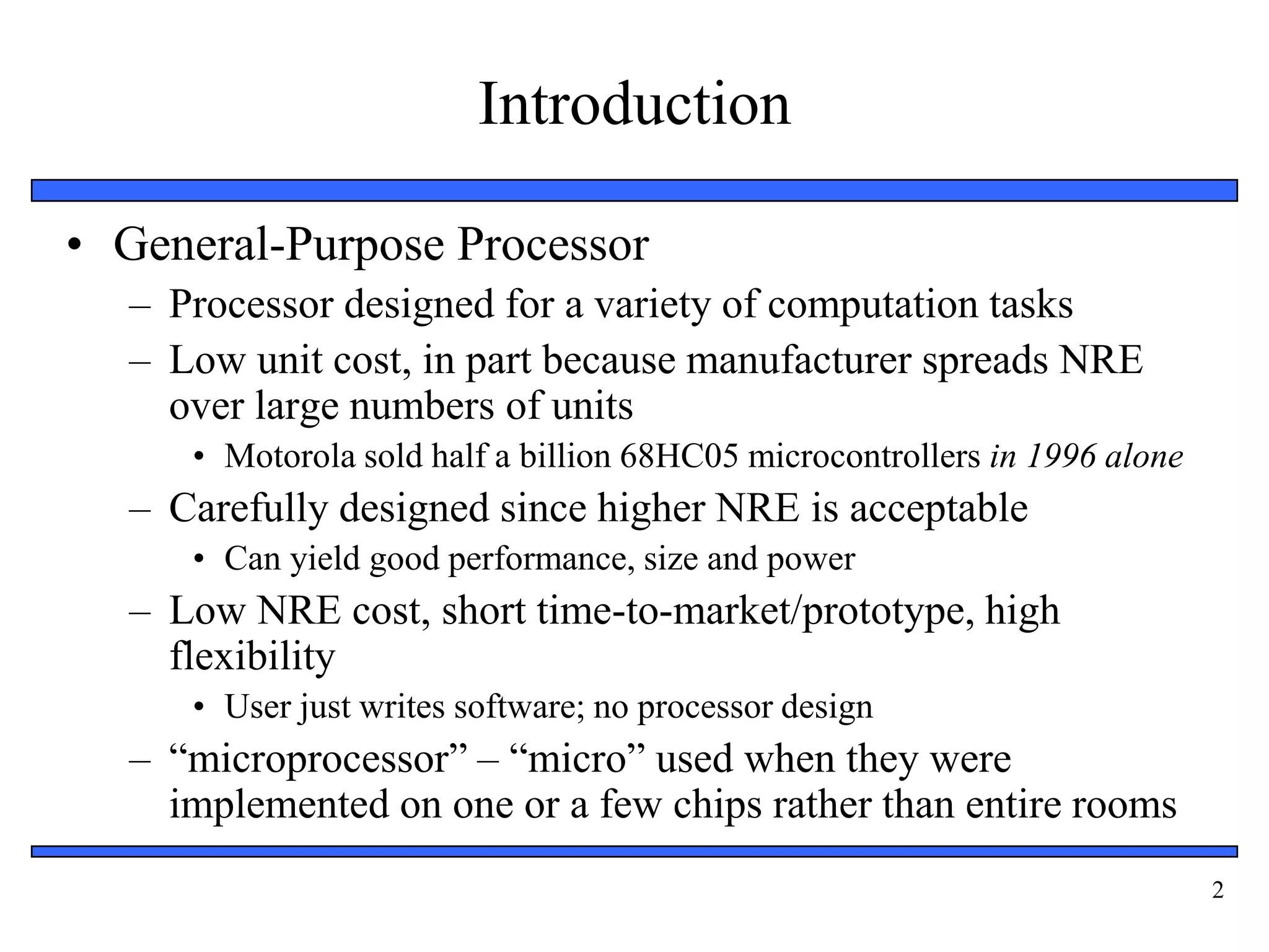
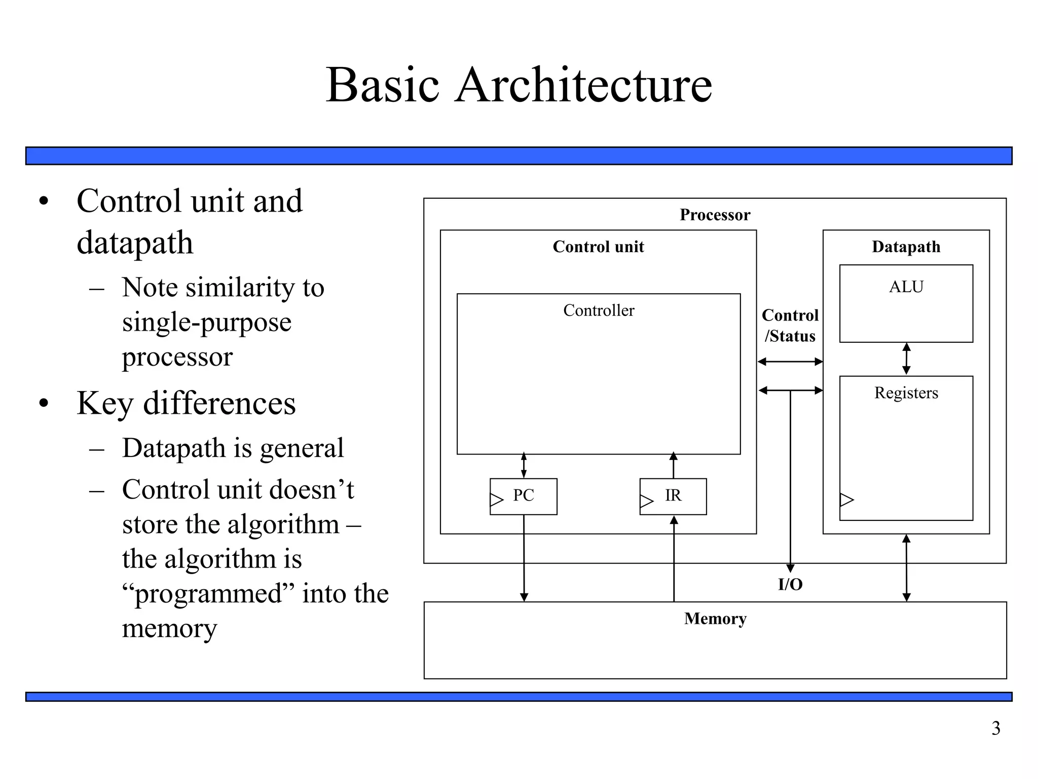
1
Unit 3: General-Purpose Processors
2
Introduction
• General-Purpose Processor
– Processor designed for a variety of computation tasks
– Low unit cost, in part because manufacturer spreads NRE
over large numbers of units
• Motorola sold half a billion 68HC05 microcontrollers in 1996 alone
– Carefully designed since higher NRE is acceptable
• Can yield good performance, size and power
– Low NRE cost, short time-to-market/prototype, high
flexibility
• User just writes software; no processor design
– “microprocessor” – “micro” used when they were
implemented on one or a few chips rather than entire rooms
3
Basic Architecture
• Control unit and
datapath
– Note similarity to
single-purpose
processor
• Key differences
– Datapath is general
– Control unit doesn’t
store the algorithm –
the algorithm is
“programmed” into the
memory
Processor
Control unit Datapath
ALU
Registers
IR
PC
Controller
Memory
I/O
Control
/Status
4
Datapath Operations
• Load
– Read memory location
into register
• ALU operation
– Input certain registers
through ALU, store
back in register
• Store
– Write register to
memory location
Processor
Control unit Datapath
ALU
Registers
IR
PC
Controller
Memory
I/O
Control
/Status
10
...
...
10
+1
11
11
5
Control Unit
• Control unit: configures the datapath
operations
– Sequence of desired operations
(“instructions”) stored in memory –
“program”
• Instruction cycle – broken into
several sub-operations, each one
clock cycle, e.g.:
– Fetch: Get next instruction into IR
– Decode: Determine what the
instruction means
– Fetch operands: Move data from
memory to datapath register
– Execute: Move data through the
ALU
– Store results: Write data from
register to memory
Processor
Control unit Datapath
ALU
Registers
IR
PC
Controller
Memory
I/O
Control
/Status
10
...
...
load R0, M[500]
500
501
100
inc R1, R0
101
store M[501], R1
102
R0 R1
6
Control Unit Sub-Operations
• Fetch
– Get next instruction
into IR
– PC: program
counter, always
points to next
instruction
– IR: holds the
fetched instruction
Processor
Control unit Datapath
ALU
Registers
IR
PC
Controller
Memory
I/O
Control
/Status
10
...
...
load R0, M[500]
500
501
100
inc R1, R0
101
store M[501], R1
102
R0 R1
100
load R0, M[500]
7
Control Unit Sub-Operations
• Decode
– Determine what the
instruction means
Processor
Control unit Datapath
ALU
Registers
IR
PC
Controller
Memory
I/O
Control
/Status
10
...
...
load R0, M[500]
500
501
100
inc R1, R0
101
store M[501], R1
102
R0 R1
100
load R0, M[500]
8
Control Unit Sub-Operations
• Fetch operands
– Move data from
memory to datapath
register
Processor
Control unit Datapath
ALU
Registers
IR
PC
Controller
Memory
I/O
Control
/Status
10
...
...
load R0, M[500]
500
501
100
inc R1, R0
101
store M[501], R1
102
R0 R1
100
load R0, M[500]
10
9
Control Unit Sub-Operations
• Execute
– Move data through
the ALU
– This particular
instruction does
nothing during this
sub-operation
Processor
Control unit Datapath
ALU
Registers
IR
PC
Controller
Memory
I/O
Control
/Status
10
...
...
load R0, M[500]
500
501
100
inc R1, R0
101
store M[501], R1
102
R0 R1
100
load R0, M[500]
10
10
Control Unit Sub-Operations
• Store results
– Write data from
register to memory
– This particular
instruction does
nothing during this
sub-operation
Processor
Control unit Datapath
ALU
Registers
IR
PC
Controller
Memory
I/O
Control
/Status
10
...
...
load R0, M[500]
500
501
100
inc R1, R0
101
store M[501], R1
102
R0 R1
100
load R0, M[500]
10
11
Instruction Cycles
Processor
Control unit Datapath
ALU
Registers
IR
PC
Controller
Memory
I/O
Control
/Status
10
...
...
load R0, M[500]
500
501
100
inc R1, R0
101
store M[501], R1
102
R0 R1
PC=100
10
Fetch
ops
Exec. Store
results
clk
Fetch
load R0, M[500]
Decode
100
12
Instruction Cycles
Processor
Control unit Datapath
ALU
Registers
IR
PC
Controller
Memory
I/O
Control
/Status
10
...
...
load R0, M[500]
500
501
100
inc R1, R0
101
store M[501], R1
102
R0 R1
10
PC=100
Fetch Decode Fetch
ops
Exec. Store
results
clk
PC=101
inc R1, R0
Fetch Fetch
ops
+1
11
Exec. Store
results
clk
101
Decode
13
Instruction Cycles
Processor
Control unit Datapath
ALU
Registers
IR
PC
Controller
Memory
I/O
Control
/Status
10
...
...
load R0, M[500]
500
501
100
inc R1, R0
101
store M[501], R1
102
R0 R1
11
10
PC=100
Fetch Decode Fetch
ops
Exec. Store
results
clk
PC=101
Fetch Decode Fetch
ops
Exec. Store
results
clk
PC=102
store M[501], R1
Fetch Fetch
ops
Exec.
11
Store
results
clk
Decode
102
14
Architectural Considerations
• N-bit processor
– N-bit ALU, registers,
buses, memory data
interface
– Embedded: 8-bit, 16-
bit, 32-bit common
– Desktop/servers: 32-
bit, even 64
• PC size determines
address space
Processor
Control unit Datapath
ALU
Registers
IR
PC
Controller
Memory
I/O
Control
/Status
15
Architectural Considerations
• Clock frequency
– Inverse of clock
period
– Must be longer than
longest register to
register delay in
entire processor
– Memory access is
often the longest
Processor
Control unit Datapath
ALU
Registers
IR
PC
Controller
Memory
I/O
Control
/Status
16
Pipelining: Increasing Instruction
Throughput
1 2 3 4 5 6 7 8
1 2 3 4 5 6 7 8
1 2 3 4 5 6 7 8
1 2 3 4 5 6 7 8
Fetch-instr.
Decode
Fetch ops.
Execute
Store res.
1 2 3 4 5 6 7 8
1 2 3 4 5 6 7 8
1 2 3 4 5 6 7 8
1 2 3 4 5 6 7 8
1 2 3 4 5 6 7 8
Wash
Dry
Time
Non-pipelined Pipelined
Time
Time
Pipelined
pipelined instruction execution
non-pipelined dish cleaning pipelined dish cleaning
Instruction 1
17
Superscalar and VLIW Architectures
• Performance can be improved by:
– Faster clock (but there’s a limit)
– Pipelining: slice up instruction into stages, overlap stages
– Multiple ALUs to support more than one instruction stream
• Superscalar
– Scalar: non-vector operations
– Fetches instructions in batches, executes as many as possible
• May require extensive hardware to detect independent instructions
– VLIW: each word in memory has multiple independent instructions
• Relies on the compiler to detect and schedule instructions
• Currently growing in popularity
18
Two Memory Architectures
Processor
Program
memory
Data memory
Processor
Memory
(program and data)
Harvard Princeton
• Princeton
– Fewer memory
wires
• Harvard
– Simultaneous
program and data
memory access
19
Cache Memory
• Memory access may be slow
• Cache is small but fast
memory close to processor
– Holds copy of part of memory
– Hits and misses
Processor
Memory
Cache
Fast/expensive technology, usually on
the same chip
Slower/cheaper technology, usually on
a different chip
20
Programmer’s View
• Programmer doesn’t need detailed understanding of architecture
– Instead, needs to know what instructions can be executed
• Two levels of instructions:
– Assembly level
– Structured languages (C, C++, Java, etc.)
• Most development today done using structured languages
– But, some assembly level programming may still be necessary
– Drivers: portion of program that communicates with and/or controls
(drives) another device
• Often have detailed timing considerations, extensive bit manipulation
• Assembly level may be best for these
21
Assembly-Level Instructions
opcode operand1 operand2
...
Instruction 1
Instruction 2
Instruction 3
Instruction 4
• Instruction Set
– Defines the legal set of instructions for that processor
• Data transfer: memory/register, register/register, I/O, etc.
• Arithmetic/logical: move register through ALU and back
• Branches: determine next PC value when not just PC+1
22
A Simple (Trivial) Instruction Set
opcode operands
MOV Rn, direct
MOV @Rn, Rm
ADD Rn, Rm
0000 Rn direct
0010 Rn
0100 Rm
Rn
Rn = M(direct)
Rn = Rn + Rm
SUB Rn, Rm 0101 Rm Rn = Rn - Rm
MOV Rn, #immed. 0011 Rn immediate Rn = immediate
Assembly instruct. First byte Second byte Operation
JZ Rn, relative 0110 Rn relative PC = PC+ relative
(only if Rn is 0)
Rn
MOV direct, Rn 0001 Rn direct M(direct) = Rn
Rm M(Rn) = Rm
23
Addressing Modes
Data
Immediate
Register-direct
Register
indirect
Direct
Indirect
Data
Operand field
Register address
Register address
Memory address
Memory address
Memory address Data
Data
Memory address
Data
Addressing
mode
Register-file
contents
Memory
contents
24
Sample Programs
int total = 0;
for (int i=10; i!=0; i--)
total += i;
// next instructions...
C program
MOV R0, #0; // total = 0
MOV R1, #10; // i = 10
JZ R1, Next; // Done if i=0
ADD R0, R1; // total += i
MOV R2, #1; // constant 1
JZ R3, Loop; // Jump always
Loop:
Next: // next instructions...
SUB R1, R2; // i--
Equivalent assembly program
MOV R3, #0; // constant 0
0
1
2
3
5
6
7
• Try some others
– Handshake: Wait until the value of M[254] is not 0, set M[255] to 1, wait
until M[254] is 0, set M[255] to 0 (assume those locations are ports).
– (Harder) Count the occurrences of zero in an array stored in memory
locations 100 through 199.
25
Programmer Considerations
• Program and data memory space
– Embedded processors often very limited
• e.g., 64 Kbytes program, 256 bytes of RAM (expandable)
• Registers: How many are there?
– Only a direct concern for assembly-level programmers
• I/O
– How to communicate with external signals?
• Interrupts
27
Example: parallel port driver
• Using assembly language programming we can configure a PC
parallel port to perform digital I/O
– write and read to three special registers to accomplish this table provides
list of parallel port connector pins and corresponding register location
– Example : parallel port monitors the input switch and turns the LED
on/off accordingly
PC Parallel port
Pin 13
Pin 2
Switch
LED
LPT Connection Pin I/O Direction Register Address
1 Output 0th bit of register #2
2-9 Output 0th bit of register #2
14,16,17 Output 1,2,3th bit of register #2
10,11,12,13,15 Input 6,7,5,4,3th bit of register #1
28
Parallel Port Example
; This program consists of a sub-routine that reads
; the state of the input pin, determining the on/off state
; of our switch and asserts the output pin, turning the LED
; on/off accordingly
.386
CheckPort proc
push ax ; save the content
push dx ; save the content
mov dx, 3BCh + 1 ; base + 1 for register #1
in al, dx ; read register #1
and al, 10h ; mask out all but bit # 4
cmp al, 0 ; is it 0?
jne SwitchOn ; if not, we need to turn the LED on
SwitchOff:
mov dx, 3BCh + 0 ; base + 0 for register #0
in al, dx ; read the current state of the port
and al, f7h ; clear first bit (masking)
out dx, al ; write it out to the port
jmp Done ; we are done
SwitchOn:
mov dx, 3BCh + 0 ; base + 0 for register #0
in al, dx ; read the current state of the port
or al, 01h ; set first bit (masking)
out dx, al ; write it out to the port
Done: pop dx ; restore the content
pop ax ; restore the content
CheckPort endp
extern “C” CheckPort(void); // defined in
// assembly
void main(void) {
while( 1 ) {
CheckPort();
}
}
LPT Connection Pin I/O Direction Register Address
1 Output 0th bit of register #2
2-9 Output 0th bit of register #2
14,16,17 Output 1,2,3th bit of register #2
10,11,12,13,15 Input 6,7,5,4,3th bit of register
#1
PC Parallel port
Pin 13
Pin 2
Switch
LED
29
Operating System
• Optional software layer
providing low-level services to
a program (application).
– File management, disk access
– Keyboard/display interfacing
– Scheduling multiple programs for
execution
• Or even just multiple threads from
one program
– Program makes system calls to
the OS
DB file_name “out.txt” -- store file name
MOV R0, 1324 -- system call “open” id
MOV R1, file_name -- address of file-name
INT 34 -- cause a system call
JZ R0, L1 -- if zero -> error
. . . read the file
JMP L2 -- bypass error cond.
L1:
. . . handle the error
L2:
30
Development Environment
• Development processor
– The processor on which we write and debug our programs
• Usually a PC
• Target processor
– The processor that the program will run on in our embedded
system
• Often different from the development processor
Development processor Target processor
31
Software Development Process
Compiler
Linker
C File C File Asm.
File
Binary
File
Binary
File
Binary
File
Exec.
File
Assemble
r
Library
Implementation Phase
Debugger
Profiler
Verification Phase
• Compilers
– Cross compiler
• Runs on one
processor, but
generates code for
another
• Assemblers
• Linkers
• Debuggers
• Profilers
32
Running a Program
• If development processor is different than target, how
can we run our compiled code? Two options:
– Download to target processor
– Simulate
• Simulation
– One method: Hardware description language
• But slow, not always available
– Another method: Instruction set simulator (ISS)
• Runs on development processor, but executes instructions of target
processor
33
Instruction Set Simulator For A Simple
Processor
#include <stdio.h>
typedef struct {
unsigned char first_byte, second_byte;
} instruction;
instruction program[1024]; //instruction memory
unsigned char memory[256]; //data memory
void run_program(int num_bytes) {
int pc = -1;
unsigned char reg[16], fb, sb;
while( ++pc < (num_bytes / 2) ) {
fb = program[pc].first_byte;
sb = program[pc].second_byte;
switch( fb >> 4 ) {
case 0: reg[fb & 0x0f] = memory[sb]; break;
case 1: memory[sb] = reg[fb & 0x0f]; break;
case 2: memory[reg[fb & 0x0f]] =
reg[sb >> 4]; break;
case 3: reg[fb & 0x0f] = sb; break;
case 4: reg[fb & 0x0f] += reg[sb >> 4]; break;
case 5: reg[fb & 0x0f] -= reg[sb >> 4]; break;
case 6: pc += sb; break;
default: return –1;
}
}
return 0;
}
int main(int argc, char *argv[]) {
FILE* ifs;
If( argc != 2 ||
(ifs = fopen(argv[1], “rb”) == NULL ) {
return –1;
}
if (run_program(fread(program,
sizeof(program) == 0) {
print_memory_contents();
return(0);
}
else return(-1);
}
34
Testing and Debugging
Implementation
Phase
Implementation
Phase
Verification
Phase
Verification
Phase
Emulator
Debugger
/ ISS
Programmer
Development processor
(a) (b)
External tools
• ISS
– Gives us control over time –
set breakpoints, look at
register values, set values,
step-by-step execution, ...
– But, doesn’t interact with real
environment
• Download to board
– Use device programmer
– Runs in real environment, but
not controllable
• Compromise: emulator
– Runs in real environment, at
speed or near
– Supports some controllability
from the PC
35
Application-Specific Instruction-Set
Processors (ASIPs)
• General-purpose processors
– Sometimes too general to be effective in demanding
application
• e.g., video processing – requires huge video buffers and operations
on large arrays of data, inefficient on a GPP
– But single-purpose processor has high NRE, not
programmable
• ASIPs – targeted to a particular domain
– Contain architectural features specific to that domain
• e.g., embedded control, digital signal processing, video processing,
network processing, telecommunications, etc.
– Still programmable
36
A Common ASIP: Microcontroller
• For embedded control applications
– Reading sensors, setting actuators
– Mostly dealing with events (bits): data is present, but not in huge
amounts
– e.g., VCR, disk drive, digital camera (assuming SPP for image
compression), washing machine, microwave oven
• Microcontroller features
– On-chip peripherals
• Timers, analog-digital converters, serial communication, etc.
• Tightly integrated for programmer, typically part of register space
– On-chip program and data memory
– Direct programmer access to many of the chip’s pins
– Specialized instructions for bit-manipulation and other low-level
operations
37
Another Common ASIP: Digital Signal
Processors (DSP)
• For signal processing applications
– Large amounts of digitized data, often streaming
– Data transformations must be applied fast
– e.g., cell-phone voice filter, digital TV, music synthesizer
• DSP features
– Several instruction execution units
– Multiple-accumulate single-cycle instruction, other instrs.
– Efficient vector operations – e.g., add two arrays
• Vector ALUs, loop buffers, etc.

UNIT 3 - General Purpose Processors

  • 1.
  • 2.
    2 Introduction • General-Purpose Processor –Processor designed for a variety of computation tasks – Low unit cost, in part because manufacturer spreads NRE over large numbers of units • Motorola sold half a billion 68HC05 microcontrollers in 1996 alone – Carefully designed since higher NRE is acceptable • Can yield good performance, size and power – Low NRE cost, short time-to-market/prototype, high flexibility • User just writes software; no processor design – “microprocessor” – “micro” used when they were implemented on one or a few chips rather than entire rooms
  • 3.
    3 Basic Architecture • Controlunit and datapath – Note similarity to single-purpose processor • Key differences – Datapath is general – Control unit doesn’t store the algorithm – the algorithm is “programmed” into the memory Processor Control unit Datapath ALU Registers IR PC Controller Memory I/O Control /Status
  • 4.
    4 Datapath Operations • Load –Read memory location into register • ALU operation – Input certain registers through ALU, store back in register • Store – Write register to memory location Processor Control unit Datapath ALU Registers IR PC Controller Memory I/O Control /Status 10 ... ... 10 +1 11 11
  • 5.
    5 Control Unit • Controlunit: configures the datapath operations – Sequence of desired operations (“instructions”) stored in memory – “program” • Instruction cycle – broken into several sub-operations, each one clock cycle, e.g.: – Fetch: Get next instruction into IR – Decode: Determine what the instruction means – Fetch operands: Move data from memory to datapath register – Execute: Move data through the ALU – Store results: Write data from register to memory Processor Control unit Datapath ALU Registers IR PC Controller Memory I/O Control /Status 10 ... ... load R0, M[500] 500 501 100 inc R1, R0 101 store M[501], R1 102 R0 R1
  • 6.
    6 Control Unit Sub-Operations •Fetch – Get next instruction into IR – PC: program counter, always points to next instruction – IR: holds the fetched instruction Processor Control unit Datapath ALU Registers IR PC Controller Memory I/O Control /Status 10 ... ... load R0, M[500] 500 501 100 inc R1, R0 101 store M[501], R1 102 R0 R1 100 load R0, M[500]
  • 7.
    7 Control Unit Sub-Operations •Decode – Determine what the instruction means Processor Control unit Datapath ALU Registers IR PC Controller Memory I/O Control /Status 10 ... ... load R0, M[500] 500 501 100 inc R1, R0 101 store M[501], R1 102 R0 R1 100 load R0, M[500]
  • 8.
    8 Control Unit Sub-Operations •Fetch operands – Move data from memory to datapath register Processor Control unit Datapath ALU Registers IR PC Controller Memory I/O Control /Status 10 ... ... load R0, M[500] 500 501 100 inc R1, R0 101 store M[501], R1 102 R0 R1 100 load R0, M[500] 10
  • 9.
    9 Control Unit Sub-Operations •Execute – Move data through the ALU – This particular instruction does nothing during this sub-operation Processor Control unit Datapath ALU Registers IR PC Controller Memory I/O Control /Status 10 ... ... load R0, M[500] 500 501 100 inc R1, R0 101 store M[501], R1 102 R0 R1 100 load R0, M[500] 10
  • 10.
    10 Control Unit Sub-Operations •Store results – Write data from register to memory – This particular instruction does nothing during this sub-operation Processor Control unit Datapath ALU Registers IR PC Controller Memory I/O Control /Status 10 ... ... load R0, M[500] 500 501 100 inc R1, R0 101 store M[501], R1 102 R0 R1 100 load R0, M[500] 10
  • 11.
    11 Instruction Cycles Processor Control unitDatapath ALU Registers IR PC Controller Memory I/O Control /Status 10 ... ... load R0, M[500] 500 501 100 inc R1, R0 101 store M[501], R1 102 R0 R1 PC=100 10 Fetch ops Exec. Store results clk Fetch load R0, M[500] Decode 100
  • 12.
    12 Instruction Cycles Processor Control unitDatapath ALU Registers IR PC Controller Memory I/O Control /Status 10 ... ... load R0, M[500] 500 501 100 inc R1, R0 101 store M[501], R1 102 R0 R1 10 PC=100 Fetch Decode Fetch ops Exec. Store results clk PC=101 inc R1, R0 Fetch Fetch ops +1 11 Exec. Store results clk 101 Decode
  • 13.
    13 Instruction Cycles Processor Control unitDatapath ALU Registers IR PC Controller Memory I/O Control /Status 10 ... ... load R0, M[500] 500 501 100 inc R1, R0 101 store M[501], R1 102 R0 R1 11 10 PC=100 Fetch Decode Fetch ops Exec. Store results clk PC=101 Fetch Decode Fetch ops Exec. Store results clk PC=102 store M[501], R1 Fetch Fetch ops Exec. 11 Store results clk Decode 102
  • 14.
    14 Architectural Considerations • N-bitprocessor – N-bit ALU, registers, buses, memory data interface – Embedded: 8-bit, 16- bit, 32-bit common – Desktop/servers: 32- bit, even 64 • PC size determines address space Processor Control unit Datapath ALU Registers IR PC Controller Memory I/O Control /Status
  • 15.
    15 Architectural Considerations • Clockfrequency – Inverse of clock period – Must be longer than longest register to register delay in entire processor – Memory access is often the longest Processor Control unit Datapath ALU Registers IR PC Controller Memory I/O Control /Status
  • 16.
    16 Pipelining: Increasing Instruction Throughput 12 3 4 5 6 7 8 1 2 3 4 5 6 7 8 1 2 3 4 5 6 7 8 1 2 3 4 5 6 7 8 Fetch-instr. Decode Fetch ops. Execute Store res. 1 2 3 4 5 6 7 8 1 2 3 4 5 6 7 8 1 2 3 4 5 6 7 8 1 2 3 4 5 6 7 8 1 2 3 4 5 6 7 8 Wash Dry Time Non-pipelined Pipelined Time Time Pipelined pipelined instruction execution non-pipelined dish cleaning pipelined dish cleaning Instruction 1
  • 17.
    17 Superscalar and VLIWArchitectures • Performance can be improved by: – Faster clock (but there’s a limit) – Pipelining: slice up instruction into stages, overlap stages – Multiple ALUs to support more than one instruction stream • Superscalar – Scalar: non-vector operations – Fetches instructions in batches, executes as many as possible • May require extensive hardware to detect independent instructions – VLIW: each word in memory has multiple independent instructions • Relies on the compiler to detect and schedule instructions • Currently growing in popularity
  • 18.
    18 Two Memory Architectures Processor Program memory Datamemory Processor Memory (program and data) Harvard Princeton • Princeton – Fewer memory wires • Harvard – Simultaneous program and data memory access
  • 19.
    19 Cache Memory • Memoryaccess may be slow • Cache is small but fast memory close to processor – Holds copy of part of memory – Hits and misses Processor Memory Cache Fast/expensive technology, usually on the same chip Slower/cheaper technology, usually on a different chip
  • 20.
    20 Programmer’s View • Programmerdoesn’t need detailed understanding of architecture – Instead, needs to know what instructions can be executed • Two levels of instructions: – Assembly level – Structured languages (C, C++, Java, etc.) • Most development today done using structured languages – But, some assembly level programming may still be necessary – Drivers: portion of program that communicates with and/or controls (drives) another device • Often have detailed timing considerations, extensive bit manipulation • Assembly level may be best for these
  • 21.
    21 Assembly-Level Instructions opcode operand1operand2 opcode operand1 operand2 opcode operand1 operand2 opcode operand1 operand2 ... Instruction 1 Instruction 2 Instruction 3 Instruction 4 • Instruction Set – Defines the legal set of instructions for that processor • Data transfer: memory/register, register/register, I/O, etc. • Arithmetic/logical: move register through ALU and back • Branches: determine next PC value when not just PC+1
  • 22.
    22 A Simple (Trivial)Instruction Set opcode operands MOV Rn, direct MOV @Rn, Rm ADD Rn, Rm 0000 Rn direct 0010 Rn 0100 Rm Rn Rn = M(direct) Rn = Rn + Rm SUB Rn, Rm 0101 Rm Rn = Rn - Rm MOV Rn, #immed. 0011 Rn immediate Rn = immediate Assembly instruct. First byte Second byte Operation JZ Rn, relative 0110 Rn relative PC = PC+ relative (only if Rn is 0) Rn MOV direct, Rn 0001 Rn direct M(direct) = Rn Rm M(Rn) = Rm
  • 23.
    23 Addressing Modes Data Immediate Register-direct Register indirect Direct Indirect Data Operand field Registeraddress Register address Memory address Memory address Memory address Data Data Memory address Data Addressing mode Register-file contents Memory contents
  • 24.
    24 Sample Programs int total= 0; for (int i=10; i!=0; i--) total += i; // next instructions... C program MOV R0, #0; // total = 0 MOV R1, #10; // i = 10 JZ R1, Next; // Done if i=0 ADD R0, R1; // total += i MOV R2, #1; // constant 1 JZ R3, Loop; // Jump always Loop: Next: // next instructions... SUB R1, R2; // i-- Equivalent assembly program MOV R3, #0; // constant 0 0 1 2 3 5 6 7 • Try some others – Handshake: Wait until the value of M[254] is not 0, set M[255] to 1, wait until M[254] is 0, set M[255] to 0 (assume those locations are ports). – (Harder) Count the occurrences of zero in an array stored in memory locations 100 through 199.
  • 25.
    25 Programmer Considerations • Programand data memory space – Embedded processors often very limited • e.g., 64 Kbytes program, 256 bytes of RAM (expandable) • Registers: How many are there? – Only a direct concern for assembly-level programmers • I/O – How to communicate with external signals? • Interrupts
  • 26.
    27 Example: parallel portdriver • Using assembly language programming we can configure a PC parallel port to perform digital I/O – write and read to three special registers to accomplish this table provides list of parallel port connector pins and corresponding register location – Example : parallel port monitors the input switch and turns the LED on/off accordingly PC Parallel port Pin 13 Pin 2 Switch LED LPT Connection Pin I/O Direction Register Address 1 Output 0th bit of register #2 2-9 Output 0th bit of register #2 14,16,17 Output 1,2,3th bit of register #2 10,11,12,13,15 Input 6,7,5,4,3th bit of register #1
  • 27.
    28 Parallel Port Example ;This program consists of a sub-routine that reads ; the state of the input pin, determining the on/off state ; of our switch and asserts the output pin, turning the LED ; on/off accordingly .386 CheckPort proc push ax ; save the content push dx ; save the content mov dx, 3BCh + 1 ; base + 1 for register #1 in al, dx ; read register #1 and al, 10h ; mask out all but bit # 4 cmp al, 0 ; is it 0? jne SwitchOn ; if not, we need to turn the LED on SwitchOff: mov dx, 3BCh + 0 ; base + 0 for register #0 in al, dx ; read the current state of the port and al, f7h ; clear first bit (masking) out dx, al ; write it out to the port jmp Done ; we are done SwitchOn: mov dx, 3BCh + 0 ; base + 0 for register #0 in al, dx ; read the current state of the port or al, 01h ; set first bit (masking) out dx, al ; write it out to the port Done: pop dx ; restore the content pop ax ; restore the content CheckPort endp extern “C” CheckPort(void); // defined in // assembly void main(void) { while( 1 ) { CheckPort(); } } LPT Connection Pin I/O Direction Register Address 1 Output 0th bit of register #2 2-9 Output 0th bit of register #2 14,16,17 Output 1,2,3th bit of register #2 10,11,12,13,15 Input 6,7,5,4,3th bit of register #1 PC Parallel port Pin 13 Pin 2 Switch LED
  • 28.
    29 Operating System • Optionalsoftware layer providing low-level services to a program (application). – File management, disk access – Keyboard/display interfacing – Scheduling multiple programs for execution • Or even just multiple threads from one program – Program makes system calls to the OS DB file_name “out.txt” -- store file name MOV R0, 1324 -- system call “open” id MOV R1, file_name -- address of file-name INT 34 -- cause a system call JZ R0, L1 -- if zero -> error . . . read the file JMP L2 -- bypass error cond. L1: . . . handle the error L2:
  • 29.
    30 Development Environment • Developmentprocessor – The processor on which we write and debug our programs • Usually a PC • Target processor – The processor that the program will run on in our embedded system • Often different from the development processor Development processor Target processor
  • 30.
    31 Software Development Process Compiler Linker CFile C File Asm. File Binary File Binary File Binary File Exec. File Assemble r Library Implementation Phase Debugger Profiler Verification Phase • Compilers – Cross compiler • Runs on one processor, but generates code for another • Assemblers • Linkers • Debuggers • Profilers
  • 31.
    32 Running a Program •If development processor is different than target, how can we run our compiled code? Two options: – Download to target processor – Simulate • Simulation – One method: Hardware description language • But slow, not always available – Another method: Instruction set simulator (ISS) • Runs on development processor, but executes instructions of target processor
  • 32.
    33 Instruction Set SimulatorFor A Simple Processor #include <stdio.h> typedef struct { unsigned char first_byte, second_byte; } instruction; instruction program[1024]; //instruction memory unsigned char memory[256]; //data memory void run_program(int num_bytes) { int pc = -1; unsigned char reg[16], fb, sb; while( ++pc < (num_bytes / 2) ) { fb = program[pc].first_byte; sb = program[pc].second_byte; switch( fb >> 4 ) { case 0: reg[fb & 0x0f] = memory[sb]; break; case 1: memory[sb] = reg[fb & 0x0f]; break; case 2: memory[reg[fb & 0x0f]] = reg[sb >> 4]; break; case 3: reg[fb & 0x0f] = sb; break; case 4: reg[fb & 0x0f] += reg[sb >> 4]; break; case 5: reg[fb & 0x0f] -= reg[sb >> 4]; break; case 6: pc += sb; break; default: return –1; } } return 0; } int main(int argc, char *argv[]) { FILE* ifs; If( argc != 2 || (ifs = fopen(argv[1], “rb”) == NULL ) { return –1; } if (run_program(fread(program, sizeof(program) == 0) { print_memory_contents(); return(0); } else return(-1); }
  • 33.
    34 Testing and Debugging Implementation Phase Implementation Phase Verification Phase Verification Phase Emulator Debugger /ISS Programmer Development processor (a) (b) External tools • ISS – Gives us control over time – set breakpoints, look at register values, set values, step-by-step execution, ... – But, doesn’t interact with real environment • Download to board – Use device programmer – Runs in real environment, but not controllable • Compromise: emulator – Runs in real environment, at speed or near – Supports some controllability from the PC
  • 34.
    35 Application-Specific Instruction-Set Processors (ASIPs) •General-purpose processors – Sometimes too general to be effective in demanding application • e.g., video processing – requires huge video buffers and operations on large arrays of data, inefficient on a GPP – But single-purpose processor has high NRE, not programmable • ASIPs – targeted to a particular domain – Contain architectural features specific to that domain • e.g., embedded control, digital signal processing, video processing, network processing, telecommunications, etc. – Still programmable
  • 35.
    36 A Common ASIP:Microcontroller • For embedded control applications – Reading sensors, setting actuators – Mostly dealing with events (bits): data is present, but not in huge amounts – e.g., VCR, disk drive, digital camera (assuming SPP for image compression), washing machine, microwave oven • Microcontroller features – On-chip peripherals • Timers, analog-digital converters, serial communication, etc. • Tightly integrated for programmer, typically part of register space – On-chip program and data memory – Direct programmer access to many of the chip’s pins – Specialized instructions for bit-manipulation and other low-level operations
  • 36.
    37 Another Common ASIP:Digital Signal Processors (DSP) • For signal processing applications – Large amounts of digitized data, often streaming – Data transformations must be applied fast – e.g., cell-phone voice filter, digital TV, music synthesizer • DSP features – Several instruction execution units – Multiple-accumulate single-cycle instruction, other instrs. – Efficient vector operations – e.g., add two arrays • Vector ALUs, loop buffers, etc.