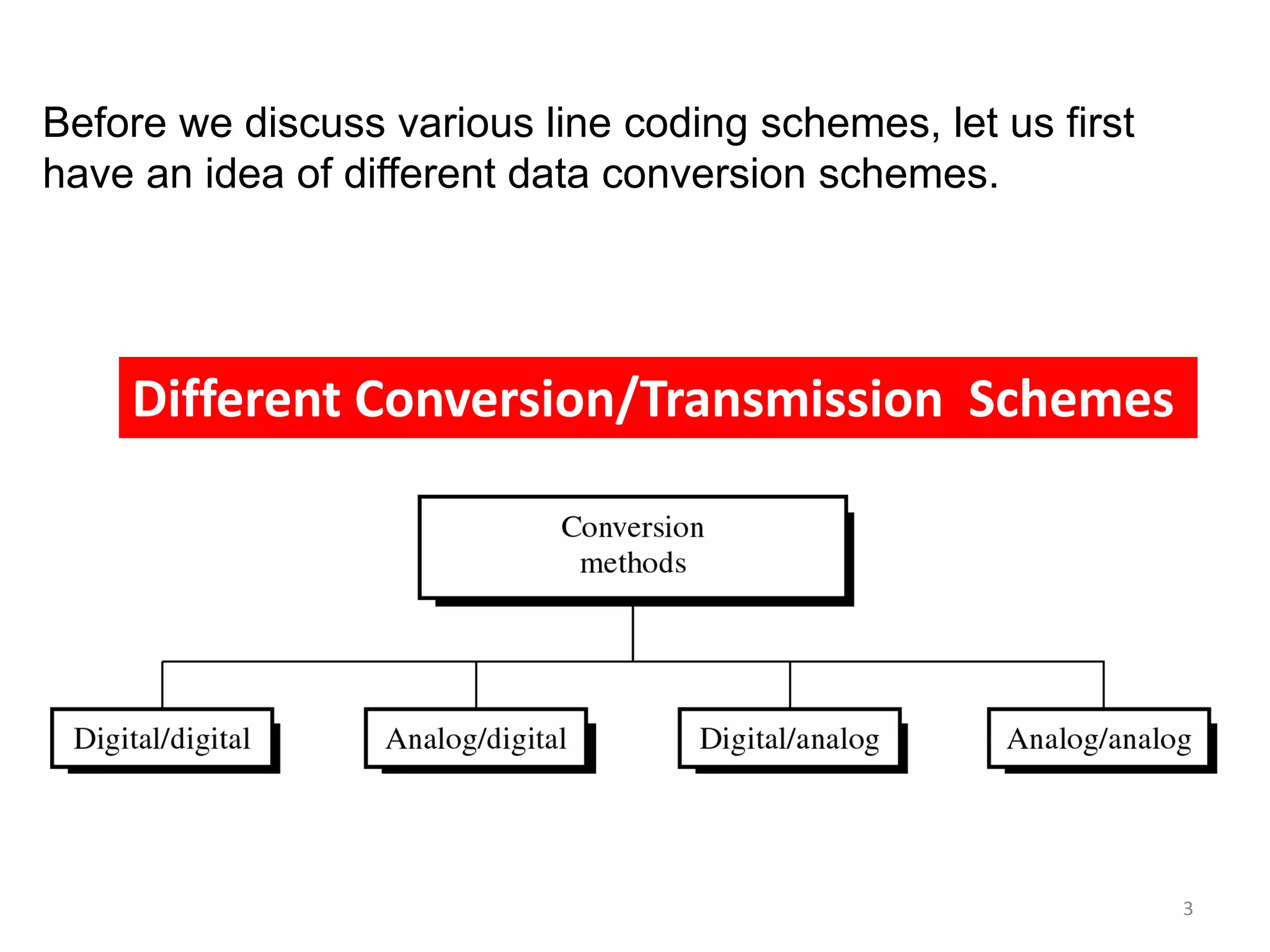
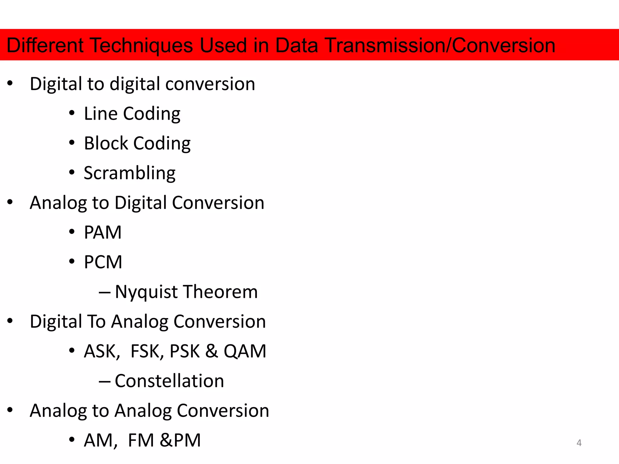
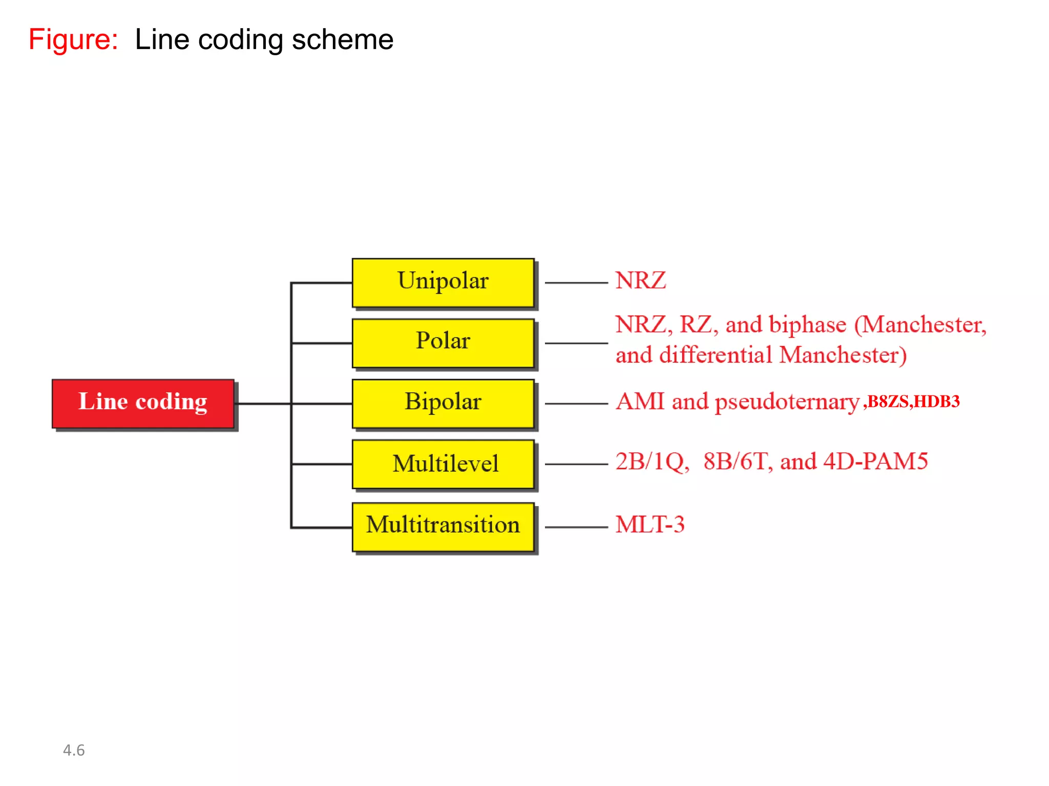
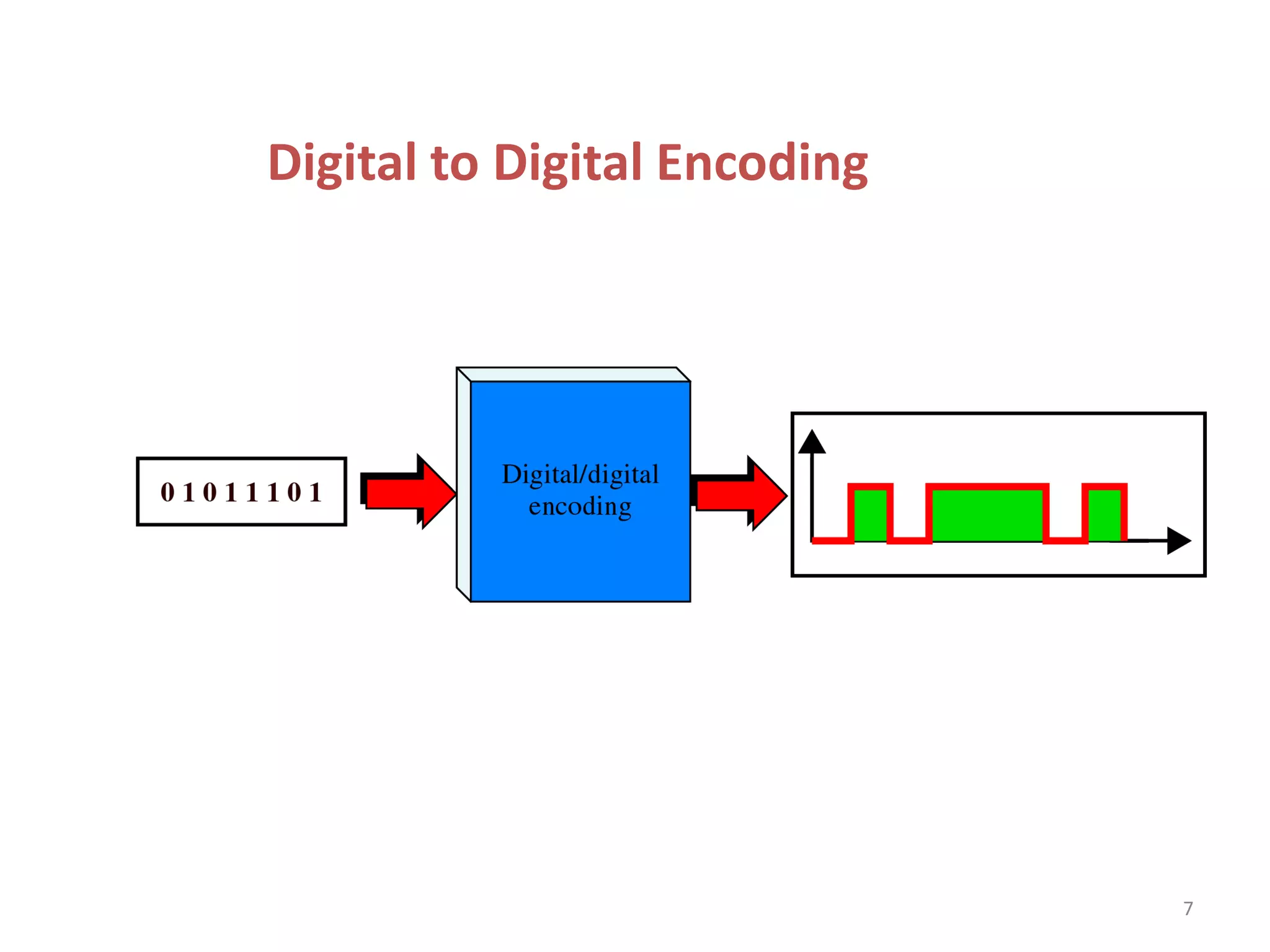
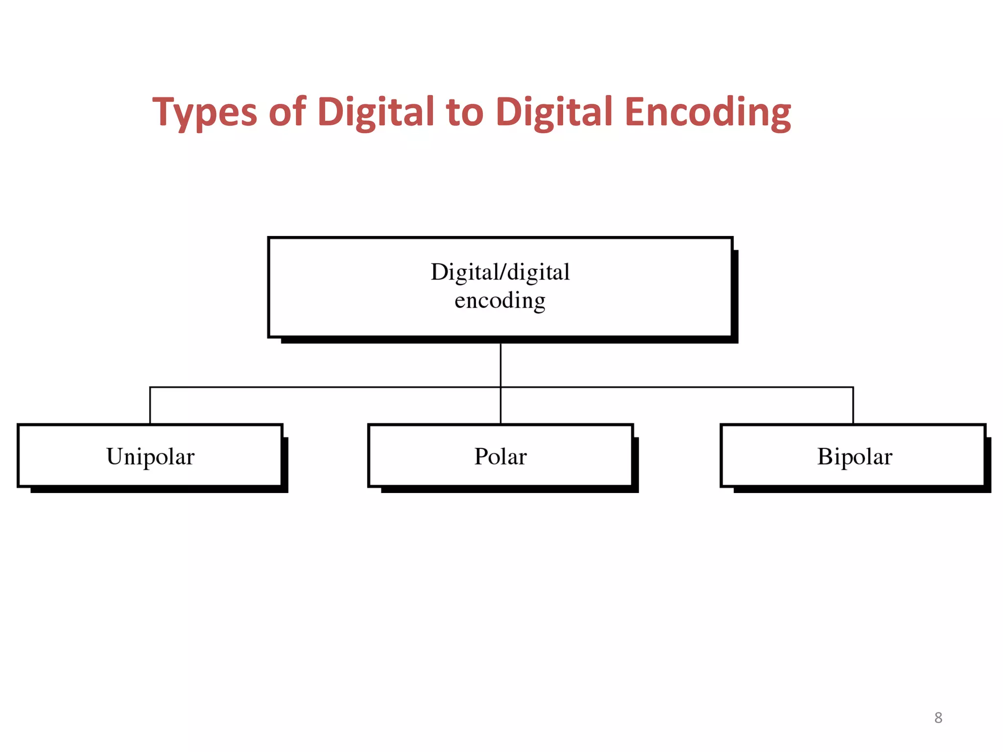
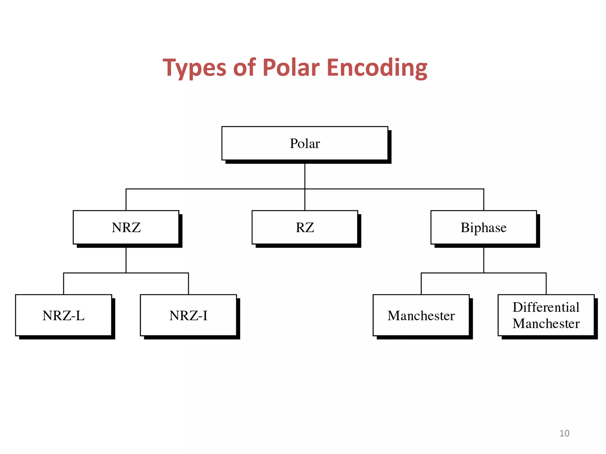
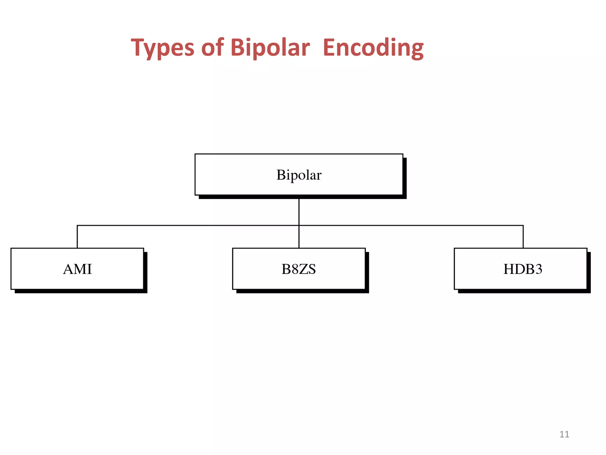
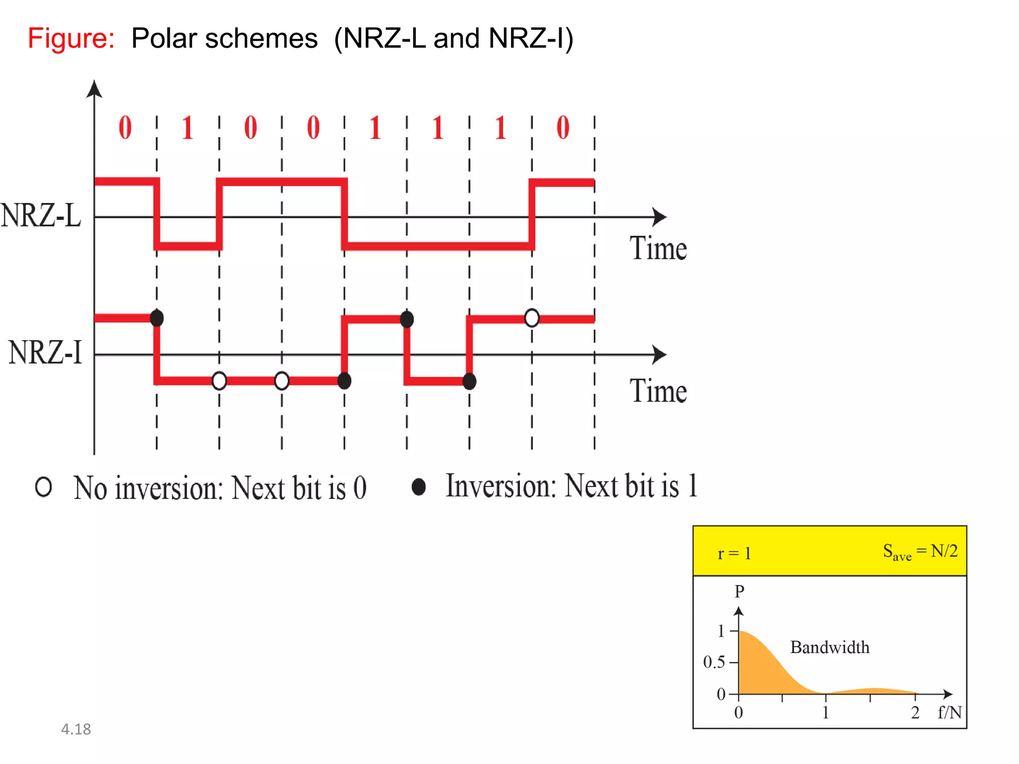
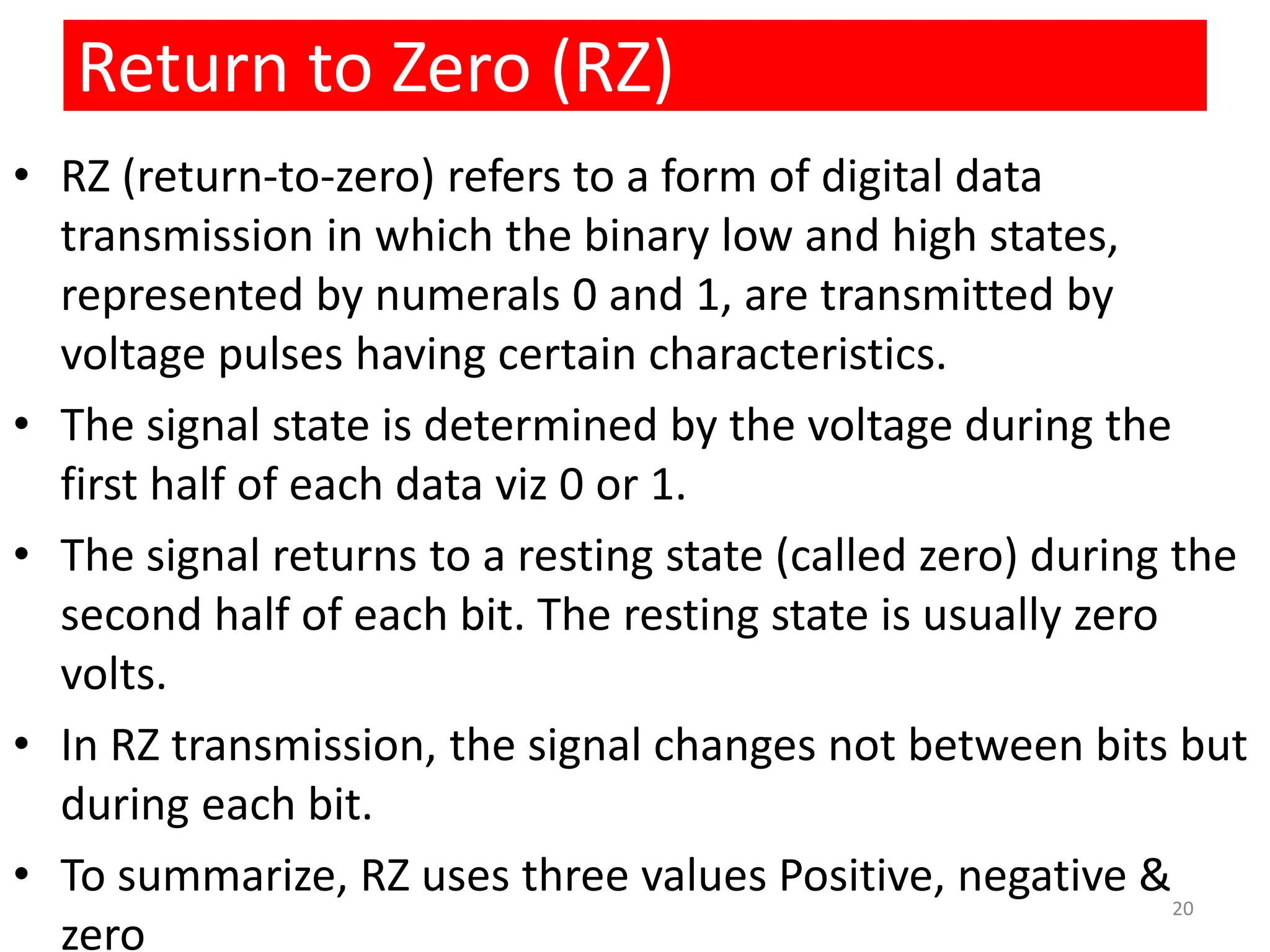
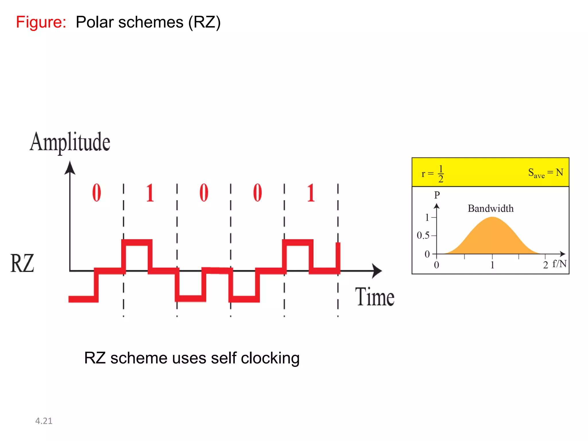
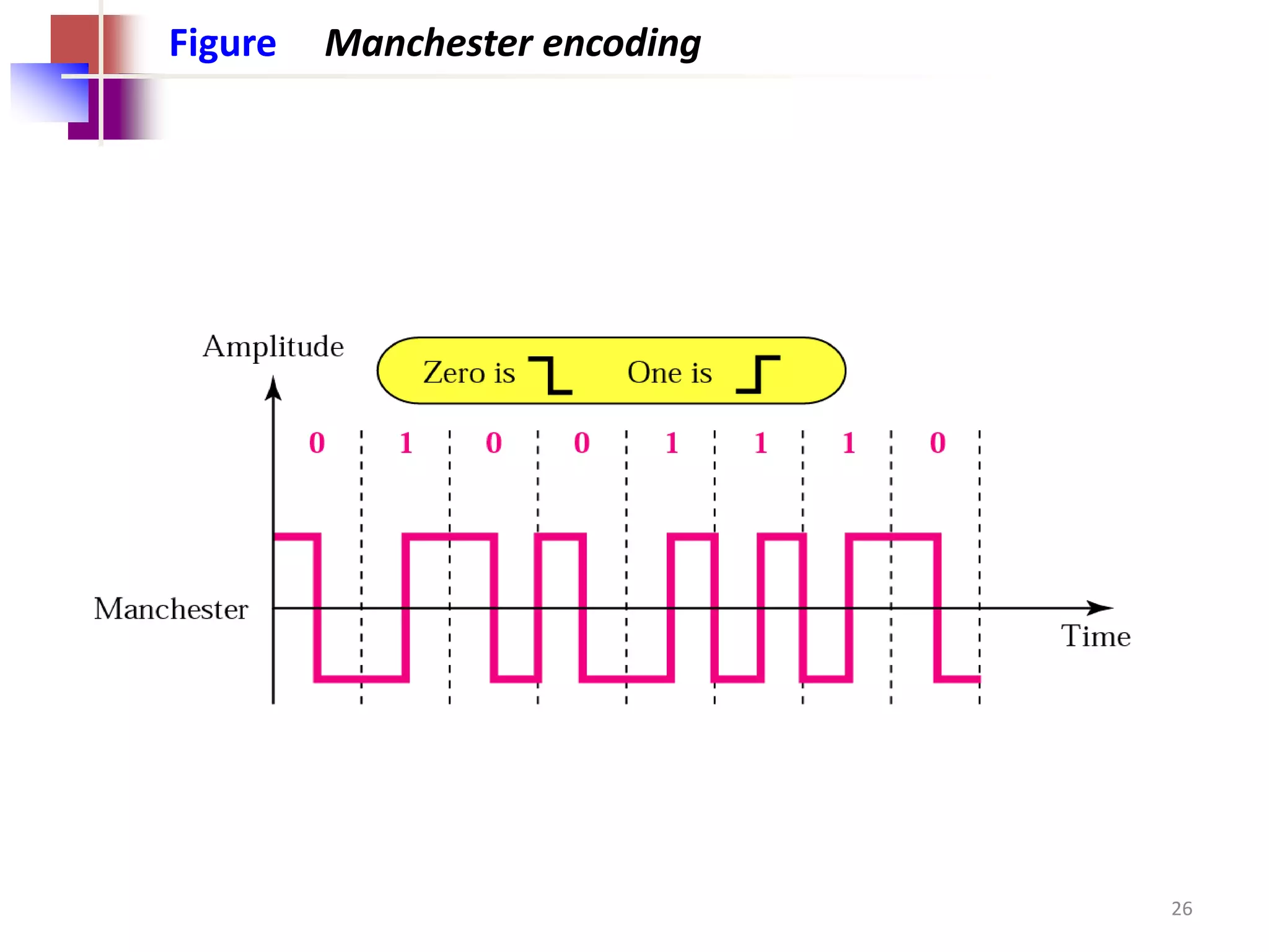
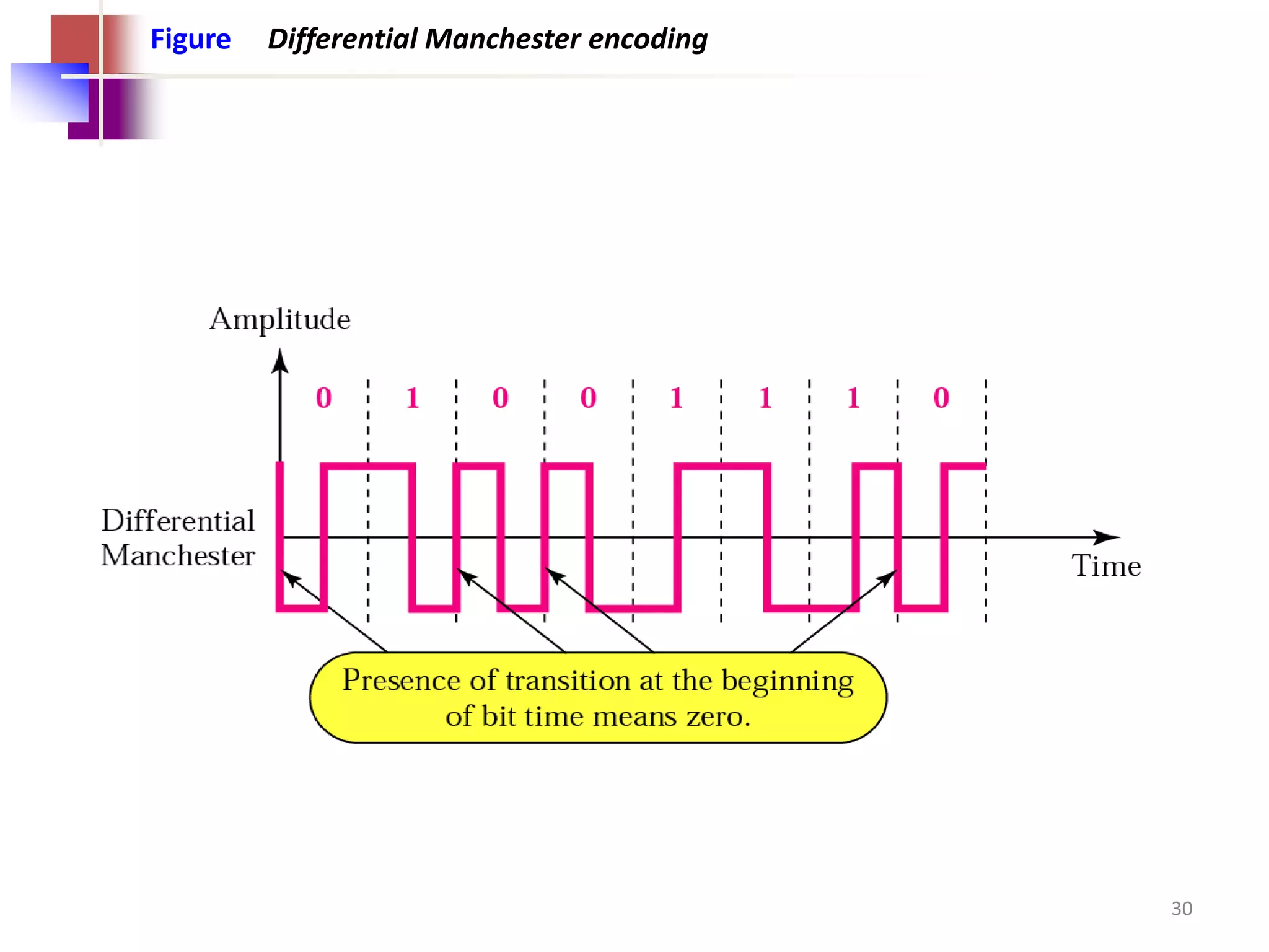
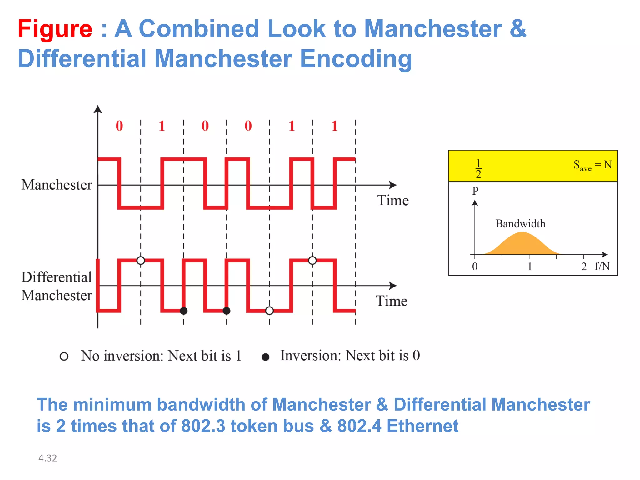
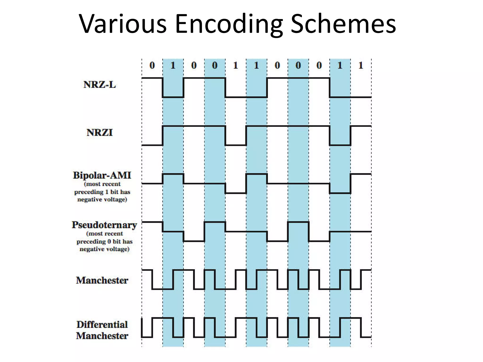
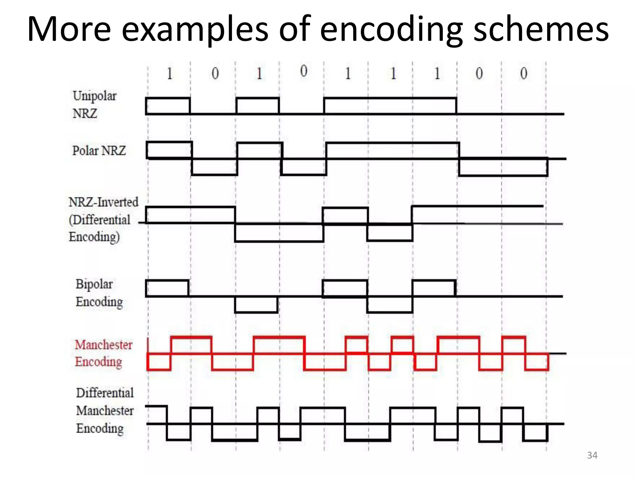
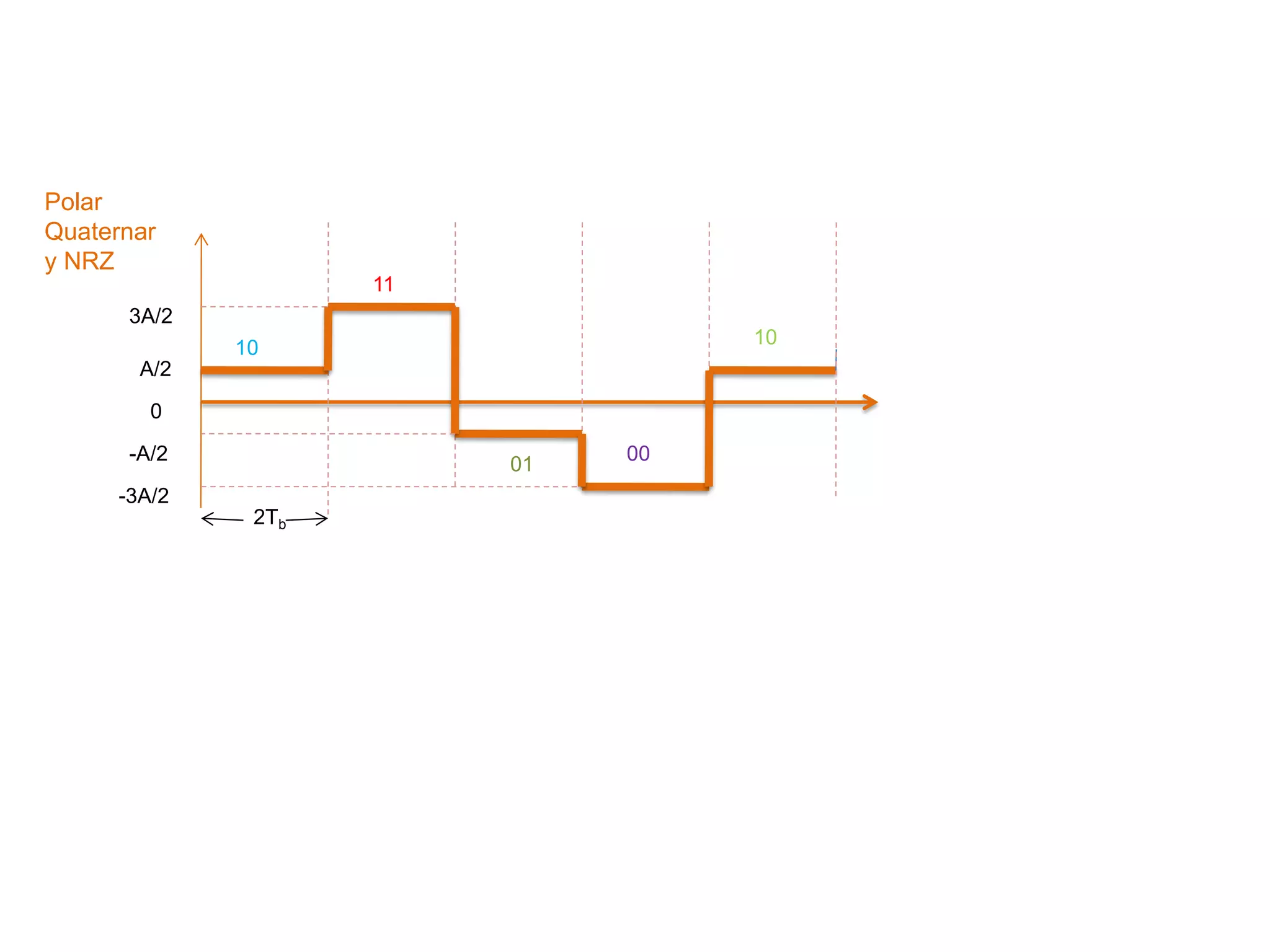
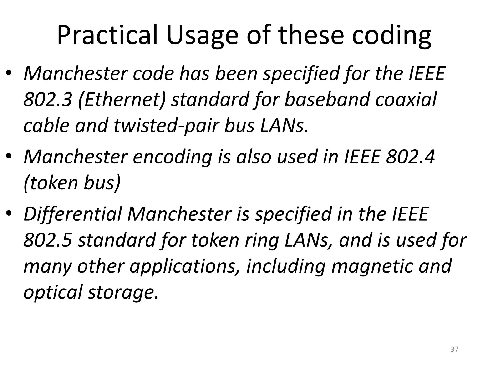
Introduction to Data communication
Topic : Unipolar and polar coding
Lecture #6
Dr Rajiv Srivastava
Director
Sagar Institute of Research & Technology (SIRT)
Sagar Group of Institutions, Bhopal
http://www.sirtbhopal.ac.in
Unit 1
Lecture 6
2
Different Conversion/Transmission Schemes
3
Before we discuss various line coding schemes, let us first
have an idea of different data conversion schemes.
• Digital to digital conversion
• Line Coding
• Block Coding
• Scrambling
• Analog to Digital Conversion
• PAM
• PCM
– Nyquist Theorem
• Digital To Analog Conversion
• ASK, FSK, PSK & QAM
– Constellation
• Analog to Analog Conversion
• AM, FM &PM 4
Different Techniques Used in Data Transmission/Conversion
4.5
Line Coding Schemes
• We can roughly divide line coding schemes into
five broad categories, as shown in Figure.
• There are several schemes in each category.
4.6
Figure: Line coding scheme
,B8ZS,HDB3
Digital to Digital Encoding
7
Types of Digital to Digital Encoding
8
Unipolar Encoding
9
• Unipolar encoding uses only one voltage level or one polarity
• This polarity is assigned to one of the two binary states usually the 1
& other state is usually 0
• The average amplitude of a unipolar encoded signal is nonzero. This
creates a DC component with zero frequency. That means it can
travel only through media which can handle DC component.
• This is almost an obsolete method today.
Types of Polar Encoding
10
Types of Bipolar Encoding
11
Polar encoding
• Polar encoding uses two voltage levels
(positive and negative).
• By using both levels, the average voltage level
on the line is reduced & the DC component
problem of unipolar encoding is alleviated.
• There are three most popular variations of
polar coding
1. Non Return to Zero (NRZ)
2. Return to Zero (RZ) &
3. Biphase Encoding
12
Non Return Zero (NRZ)
In NRZ encoding, the level of signal is always either
positive or negative as it does not return to zero. The
two most popular methods of NRZ transmission are:
1. NRZ-L (NRZ Level)
2. NRZ-I (NRZ Inversion)
NRZ-L : in NRZ-L encoding, the type of the signal
depends on the type of bit it represents.
– A positive voltage usually means the bit is 0
– negative voltage means bit is 1 or vice versa.
Thus the level of voltage depends on the level of the
bit. 13
• NRZ-I
– It is a method, in which the inversion of the voltage
level represents a 1 bit.
– It is a transition between a positive & a negative
voltage, not the voltages themselves that represent
a 1 bit.
– A 0 bit is represented by no change.
• Out of two methods the NRZ-I is superior to
NRZ-L due to the synchronization provided by
the signal change each time a 1 bit is
encountered. The existence of 1s in the data
stream allows the receiver to resynchronize. 14
In NRZ-L the level of the signal is
dependent upon the state of the bit.
Tips
15
In NRZ-I the signal is inverted if a 1 is
encountered.
NRZ-I is used in USB, Compact
CD & Fast Ethernet
0 1 0 0 1 1 1 0
NRZ-L
NRZ-I
Binary Data
Figure NRZ-L and NRZ-I encoding
time
time
Transition because
next bit is 1.
Amplitude
Variation 1 : When 0 is low
voltage.
Figure NRZ-L and NRZ-I encoding
17
VARIATION 2 : WHEN 0 IS
HIGH VOLTAGE
4.18
Figure: Polar schemes (NRZ-L and NRZ-I)
A system is using NRZ-I to transfer 1-Mbps data. What are
the average signal rate and minimum bandwidth?
Example
Solution
The average signal rate in NRZ-I coding is S = N/2
= 500 kbaud.
The minimum bandwidth for this average baud rate
is
Bmin = S = 500 kHz.
4.19
19
Return to Zero (RZ)
• RZ (return-to-zero) refers to a form of digital data
transmission in which the binary low and high states,
represented by numerals 0 and 1, are transmitted by
voltage pulses having certain characteristics.
• The signal state is determined by the voltage during the
first half of each data viz 0 or 1.
• The signal returns to a resting state (called zero) during the
second half of each bit. The resting state is usually zero
volts.
• In RZ transmission, the signal changes not between bits but
during each bit.
• To summarize, RZ uses three values Positive, negative &
zero
20
4.21
Figure: Polar schemes (RZ)
RZ scheme uses self clocking
A good encoded digital signal must
contain a provision for
synchronization.
Tip
22
Biphase Encoding
• The best solution to the problem of
synchronization is biphase encoding.
• In this method the signal changes at the
middle of the bit but does not return to zero.
• Instead it continues to the opposite pole.
• It has two variations
1. Manchester encoding
2. Differential Manchester Encoding
23
Manchester Encoding
• In telecommunication and data storage,
Manchester coding (also known as phase encoding,
or PE) is a line code in which the encoding of each
data bit has at least one transition and occupies the
same time.
• It therefore has no DC component, and is self-
clocking.
24
Manchester Encoding
• Manchester encoding uses the inversion at the
middle of each bit interval for both synchronization
and bit representation.
• A negative-to-positive transition represents binary 1
and a positive-to-negative transition represents
binary 0.
• By using a single transition for a dual purpose,
Manchester encoding achieves the same level of
synchronization as RZ but with only two levels of
amplitude.
25
Figure Manchester encoding
26
In Manchester encoding, the transition
at the middle of the bit is used for
both synchronization and bit
representation.
Tip
27
Differential Manchester Encoding
• Differential Manchester encoding is a line code in
which data and clock signals are combined to form a
single 2-level self-synchronizing data stream. It is a
differential encoding, using the presence or absence of
transitions to indicate logical value.
• It is not necessary to know the polarity of the sent
signal since the information is not kept in the actual
values of the voltage but in their change:
• in other words it does not matter whether a logical 1 or
0 is received, but only whether the polarity is the same
or different from the previous value; this makes
synchronization easier.
28
Differential Manchester Encoding
• In differential Manchester, the inversion at the
middle of the bit interval is used for
synchronization, but the presence or absence of
an additional transition at the beginning of the
interval is used to identify the bit.
• A transition means binary 0 and no transition
means binary 1.
• Differential Manchester requires two signal
changes to represent binary 0 but only one to
represent binary 1.
29
Figure Differential Manchester encoding
30
In differential Manchester encoding,
the transition at the middle of the bit
is used only for synchronization.
The bit representation is defined by
the inversion or noninversion at the
beginning of the bit.
Tip
31
4.32
Figure : A Combined Look to Manchester &
Differential Manchester Encoding
The minimum bandwidth of Manchester & Differential Manchester
is 2 times that of 802.3 token bus & 802.4 Ethernet
Various Encoding Schemes
More examples of encoding schemes
34
1 0 1 1 0 1 0 0 1 0 1
0
Tb Tb
A
0
A/2
0
-A/2
A/2
0
-A/2
A
0
-A
A/2
0
-A/2
Binary Data
Unipolar
Unipolar
NRZ
Polar
RZ
Polar
NRZ
Bipolar
NRZ
(AMI)
Split phase
Manchester
Figure : Various line codes for data stream 10110100101
t
t
t
t
t
t
10
11
01
00
10
2Tb
A/2
0
-A/2
-3A/2
3A/2
Polar
Quaternar
y NRZ
Practical Usage of these coding
• Manchester code has been specified for the IEEE
802.3 (Ethernet) standard for baseband coaxial
cable and twisted-pair bus LANs.
• Manchester encoding is also used in IEEE 802.4
(token bus)
• Differential Manchester is specified in the IEEE
802.5 standard for token ring LANs, and is used for
many other applications, including magnetic and
optical storage.
37
Thank You
Dr Rajiv Srivastava
Director
Sagar Institute of Research & Technology (SIRT)
Sagar Group of Institutions, Bhopal
http://www.sirtbhopal.ac.in

Data Communication & Computer Networks : Unipolar & Polar coding

  • 1.
    Introduction to Datacommunication Topic : Unipolar and polar coding Lecture #6 Dr Rajiv Srivastava Director Sagar Institute of Research & Technology (SIRT) Sagar Group of Institutions, Bhopal http://www.sirtbhopal.ac.in
  • 2.
  • 3.
    Different Conversion/Transmission Schemes 3 Beforewe discuss various line coding schemes, let us first have an idea of different data conversion schemes.
  • 4.
    • Digital todigital conversion • Line Coding • Block Coding • Scrambling • Analog to Digital Conversion • PAM • PCM – Nyquist Theorem • Digital To Analog Conversion • ASK, FSK, PSK & QAM – Constellation • Analog to Analog Conversion • AM, FM &PM 4 Different Techniques Used in Data Transmission/Conversion
  • 5.
    4.5 Line Coding Schemes •We can roughly divide line coding schemes into five broad categories, as shown in Figure. • There are several schemes in each category.
  • 6.
    4.6 Figure: Line codingscheme ,B8ZS,HDB3
  • 7.
  • 8.
    Types of Digitalto Digital Encoding 8
  • 9.
    Unipolar Encoding 9 • Unipolarencoding uses only one voltage level or one polarity • This polarity is assigned to one of the two binary states usually the 1 & other state is usually 0 • The average amplitude of a unipolar encoded signal is nonzero. This creates a DC component with zero frequency. That means it can travel only through media which can handle DC component. • This is almost an obsolete method today.
  • 10.
    Types of PolarEncoding 10
  • 11.
    Types of BipolarEncoding 11
  • 12.
    Polar encoding • Polarencoding uses two voltage levels (positive and negative). • By using both levels, the average voltage level on the line is reduced & the DC component problem of unipolar encoding is alleviated. • There are three most popular variations of polar coding 1. Non Return to Zero (NRZ) 2. Return to Zero (RZ) & 3. Biphase Encoding 12
  • 13.
    Non Return Zero(NRZ) In NRZ encoding, the level of signal is always either positive or negative as it does not return to zero. The two most popular methods of NRZ transmission are: 1. NRZ-L (NRZ Level) 2. NRZ-I (NRZ Inversion) NRZ-L : in NRZ-L encoding, the type of the signal depends on the type of bit it represents. – A positive voltage usually means the bit is 0 – negative voltage means bit is 1 or vice versa. Thus the level of voltage depends on the level of the bit. 13
  • 14.
    • NRZ-I – Itis a method, in which the inversion of the voltage level represents a 1 bit. – It is a transition between a positive & a negative voltage, not the voltages themselves that represent a 1 bit. – A 0 bit is represented by no change. • Out of two methods the NRZ-I is superior to NRZ-L due to the synchronization provided by the signal change each time a 1 bit is encountered. The existence of 1s in the data stream allows the receiver to resynchronize. 14
  • 15.
    In NRZ-L thelevel of the signal is dependent upon the state of the bit. Tips 15 In NRZ-I the signal is inverted if a 1 is encountered. NRZ-I is used in USB, Compact CD & Fast Ethernet
  • 16.
    0 1 00 1 1 1 0 NRZ-L NRZ-I Binary Data Figure NRZ-L and NRZ-I encoding time time Transition because next bit is 1. Amplitude Variation 1 : When 0 is low voltage.
  • 17.
    Figure NRZ-L andNRZ-I encoding 17 VARIATION 2 : WHEN 0 IS HIGH VOLTAGE
  • 18.
    4.18 Figure: Polar schemes(NRZ-L and NRZ-I)
  • 19.
    A system isusing NRZ-I to transfer 1-Mbps data. What are the average signal rate and minimum bandwidth? Example Solution The average signal rate in NRZ-I coding is S = N/2 = 500 kbaud. The minimum bandwidth for this average baud rate is Bmin = S = 500 kHz. 4.19 19
  • 20.
    Return to Zero(RZ) • RZ (return-to-zero) refers to a form of digital data transmission in which the binary low and high states, represented by numerals 0 and 1, are transmitted by voltage pulses having certain characteristics. • The signal state is determined by the voltage during the first half of each data viz 0 or 1. • The signal returns to a resting state (called zero) during the second half of each bit. The resting state is usually zero volts. • In RZ transmission, the signal changes not between bits but during each bit. • To summarize, RZ uses three values Positive, negative & zero 20
  • 21.
    4.21 Figure: Polar schemes(RZ) RZ scheme uses self clocking
  • 22.
    A good encodeddigital signal must contain a provision for synchronization. Tip 22
  • 23.
    Biphase Encoding • Thebest solution to the problem of synchronization is biphase encoding. • In this method the signal changes at the middle of the bit but does not return to zero. • Instead it continues to the opposite pole. • It has two variations 1. Manchester encoding 2. Differential Manchester Encoding 23
  • 24.
    Manchester Encoding • Intelecommunication and data storage, Manchester coding (also known as phase encoding, or PE) is a line code in which the encoding of each data bit has at least one transition and occupies the same time. • It therefore has no DC component, and is self- clocking. 24
  • 25.
    Manchester Encoding • Manchesterencoding uses the inversion at the middle of each bit interval for both synchronization and bit representation. • A negative-to-positive transition represents binary 1 and a positive-to-negative transition represents binary 0. • By using a single transition for a dual purpose, Manchester encoding achieves the same level of synchronization as RZ but with only two levels of amplitude. 25
  • 26.
  • 27.
    In Manchester encoding,the transition at the middle of the bit is used for both synchronization and bit representation. Tip 27
  • 28.
    Differential Manchester Encoding •Differential Manchester encoding is a line code in which data and clock signals are combined to form a single 2-level self-synchronizing data stream. It is a differential encoding, using the presence or absence of transitions to indicate logical value. • It is not necessary to know the polarity of the sent signal since the information is not kept in the actual values of the voltage but in their change: • in other words it does not matter whether a logical 1 or 0 is received, but only whether the polarity is the same or different from the previous value; this makes synchronization easier. 28
  • 29.
    Differential Manchester Encoding •In differential Manchester, the inversion at the middle of the bit interval is used for synchronization, but the presence or absence of an additional transition at the beginning of the interval is used to identify the bit. • A transition means binary 0 and no transition means binary 1. • Differential Manchester requires two signal changes to represent binary 0 but only one to represent binary 1. 29
  • 30.
  • 31.
    In differential Manchesterencoding, the transition at the middle of the bit is used only for synchronization. The bit representation is defined by the inversion or noninversion at the beginning of the bit. Tip 31
  • 32.
    4.32 Figure : ACombined Look to Manchester & Differential Manchester Encoding The minimum bandwidth of Manchester & Differential Manchester is 2 times that of 802.3 token bus & 802.4 Ethernet
  • 33.
  • 34.
    More examples ofencoding schemes 34
  • 35.
    1 0 11 0 1 0 0 1 0 1 0 Tb Tb A 0 A/2 0 -A/2 A/2 0 -A/2 A 0 -A A/2 0 -A/2 Binary Data Unipolar Unipolar NRZ Polar RZ Polar NRZ Bipolar NRZ (AMI) Split phase Manchester Figure : Various line codes for data stream 10110100101 t t t t t t
  • 36.
  • 37.
    Practical Usage ofthese coding • Manchester code has been specified for the IEEE 802.3 (Ethernet) standard for baseband coaxial cable and twisted-pair bus LANs. • Manchester encoding is also used in IEEE 802.4 (token bus) • Differential Manchester is specified in the IEEE 802.5 standard for token ring LANs, and is used for many other applications, including magnetic and optical storage. 37
  • 38.
    Thank You Dr RajivSrivastava Director Sagar Institute of Research & Technology (SIRT) Sagar Group of Institutions, Bhopal http://www.sirtbhopal.ac.in