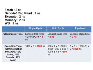
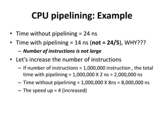
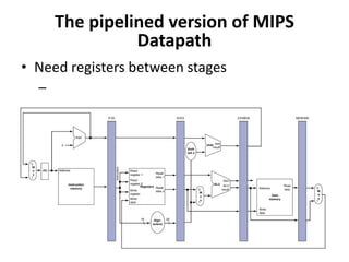
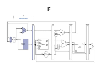
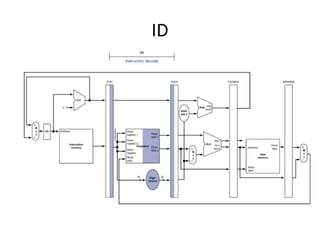
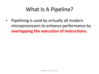
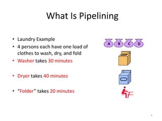
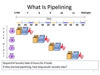
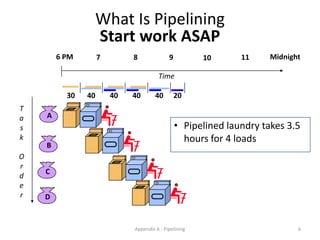
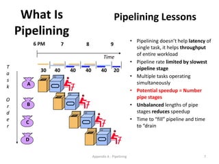
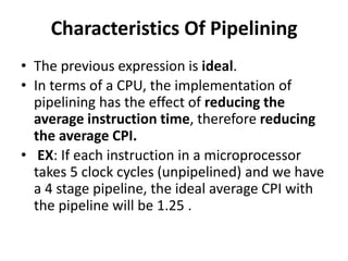
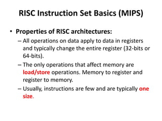
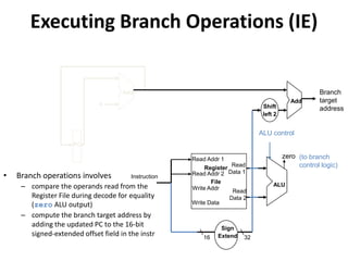
Pipelining is a technique used in computer processors to overlap the execution of instructions to enhance performance. It works by dividing instruction execution into discrete stages, such as fetch, decode, execute, memory, and write-back, so that multiple instructions can be in different stages at the same time. In a pipelined processor, the average time to complete an instruction is reduced compared to a non-pipelined processor, leading to higher throughput. However, special techniques are needed to handle data and structural hazards that can occur when instructions interact in unexpected ways within the pipeline.

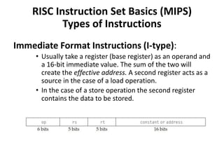
![Pipelining Theoretical
Performance
• An ideal pipeline divides a task into k independent
sequential subtasks
– Each subtask requires 1 time unit to complete
– The task itself requires k time units to complete
• For n iterations of task, the execution times:
– With no pipelining: nk time units
– With pipelining: k + (n-1) time units
• Speedup of a k-stage pipeline is
– S = nk/[k+(n-1)] → = k for large n](https://image.slidesharecdn.com/cmpn301-pipeliningv2-221224155110-ce32fb03/85/CMPN301-Pipelining_V2-pptx-8-320.jpg)


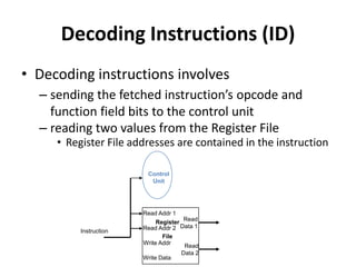
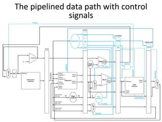
![Single Cycle Datapath with Control Unit
Read
Address
Instr[31-0]
Instruction
Memory
Add
PC
4
Write Data
Read Addr 1
Read Addr 2
Write Addr
Register
File
Read
Data 1
Read
Data 2
ALU
ovf
zero
RegWrite
Data
Memory
Address
Write Data
Read Data
MemWrite
MemRead
Sign
Extend
16 32
MemtoReg
ALUSrc
Shift
left 2
Add
PCSrc
RegDst
ALU
control
1
1
1
0
0
0
0
1
ALUOp
Instr[5-0]
Instr[15-0]
Instr[25-21]
Instr[20-16]
Instr[15
-11]
Control
Unit
Instr[31-26]
Branch](https://image.slidesharecdn.com/cmpn301-pipeliningv2-221224155110-ce32fb03/85/CMPN301-Pipelining_V2-pptx-27-320.jpg)
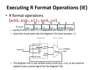
![Read
Address
Instr[31-0]
Instruction
Memory
Add
PC
4
Write Data
Read Addr 1
Read Addr 2
Write Addr
Register
File
Read
Data 1
Read
Data 2
ALU
ovf
zero
RegWrite
Data
Memory
Address
Write Data
Read Data
MemWrite
MemRead
Sign
Extend
16 32
MemtoReg
ALUSrc
Shift
left 2
Add
PCSrc
RegDst
ALU
control
1
1
1
0
0
0
0
1
ALUOp
Instr[5-0]
Instr[5-0]
Instr[25-21]
Instr[20-16]
Instr[15
-11]
Control
Unit
Instr[31-26]
Branch
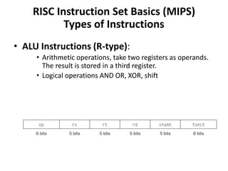
R-type Instruction Data/Control Flow](https://image.slidesharecdn.com/cmpn301-pipeliningv2-221224155110-ce32fb03/85/CMPN301-Pipelining_V2-pptx-28-320.jpg)
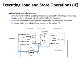
![Read
Address Instr[31-0]
Instruction
Memory
Add
PC
4
Write Data
Read Addr 1
Read Addr 2
Write Addr
Register
File
Read
Data 1
Read
Data 2
ALU
ovf
zero
RegWrite
Data
Memory
Address
Write Data
Read Data
MemWrite
MemRead
Sign
Extend
16 32
MemtoReg
ALUSrc
Shift
left 2
Add
PCSrc
RegDst
ALU
control
1
1
1
0
0 0
0
1
ALUOp
Instr[5-0]
Instr[15-0]
Instr[25-21]
Instr[20-16]
Instr[15
-11]
Control
Unit
Instr[31-26]
Branch
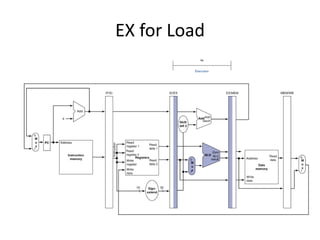
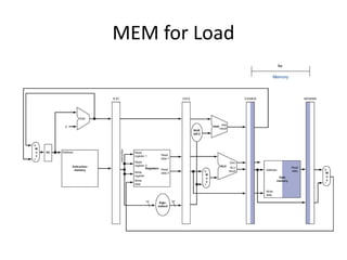
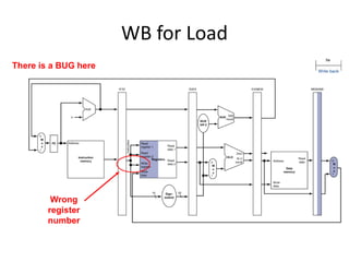
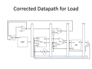
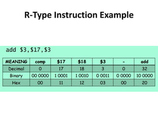
Load Word Instruction Data/Control Flow
Store Word
Instruction?](https://image.slidesharecdn.com/cmpn301-pipeliningv2-221224155110-ce32fb03/85/CMPN301-Pipelining_V2-pptx-29-320.jpg)
![Read
Address
Instr[31-0]
Instruction
Memory
Add
PC
4
Write Data
Read Addr 1
Read Addr 2
Write Addr
Register
File
Read
Data 1
Read
Data 2
ALU
ovf
zero
RegWrite
Data
Memory
Address
Write Data
Read Data
MemWrite
MemRead
Sign
Extend
16 32
MemtoReg
ALUSrc
Shift
left 2
Add
PCSrc
RegDst
ALU
control
1
1
1
0
0
0
0
1
ALUOp
Instr[5-0]
Instr[15-0]
Instr[25-21]
Instr[20-16]
Instr[15
-11]
Control
Unit
Instr[31-26]
Branch
Branch Instruction Data/Control Flow](https://image.slidesharecdn.com/cmpn301-pipeliningv2-221224155110-ce32fb03/85/CMPN301-Pipelining_V2-pptx-30-320.jpg)