Downloaded 403 times
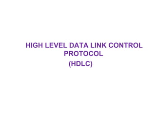
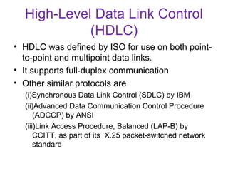
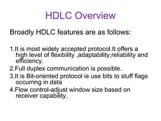
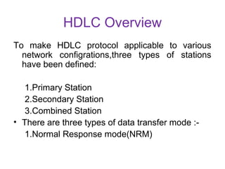
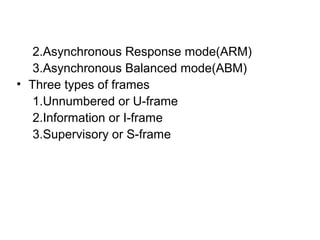
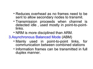
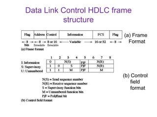
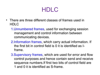


HDLC is a bit-oriented protocol defined by ISO for point-to-point and multipoint communication over data links. It supports full-duplex communication and provides reliability, efficiency and flexibility. HDLC defines three types of stations - primary, secondary and combined. It uses three frame types - unnumbered, information and supervisory frames. HDLC also specifies three data transfer modes - normal response mode, asynchronous response mode and asynchronous balanced mode. [/SUMMARY]