This document discusses transformer ratings, regulation, losses, and efficiency. It provides explanations for the following key points:
1. Transformer ratings are in kVA rather than kW because total transformer loss depends on volt-ampere (VA) and is independent of load power factor.
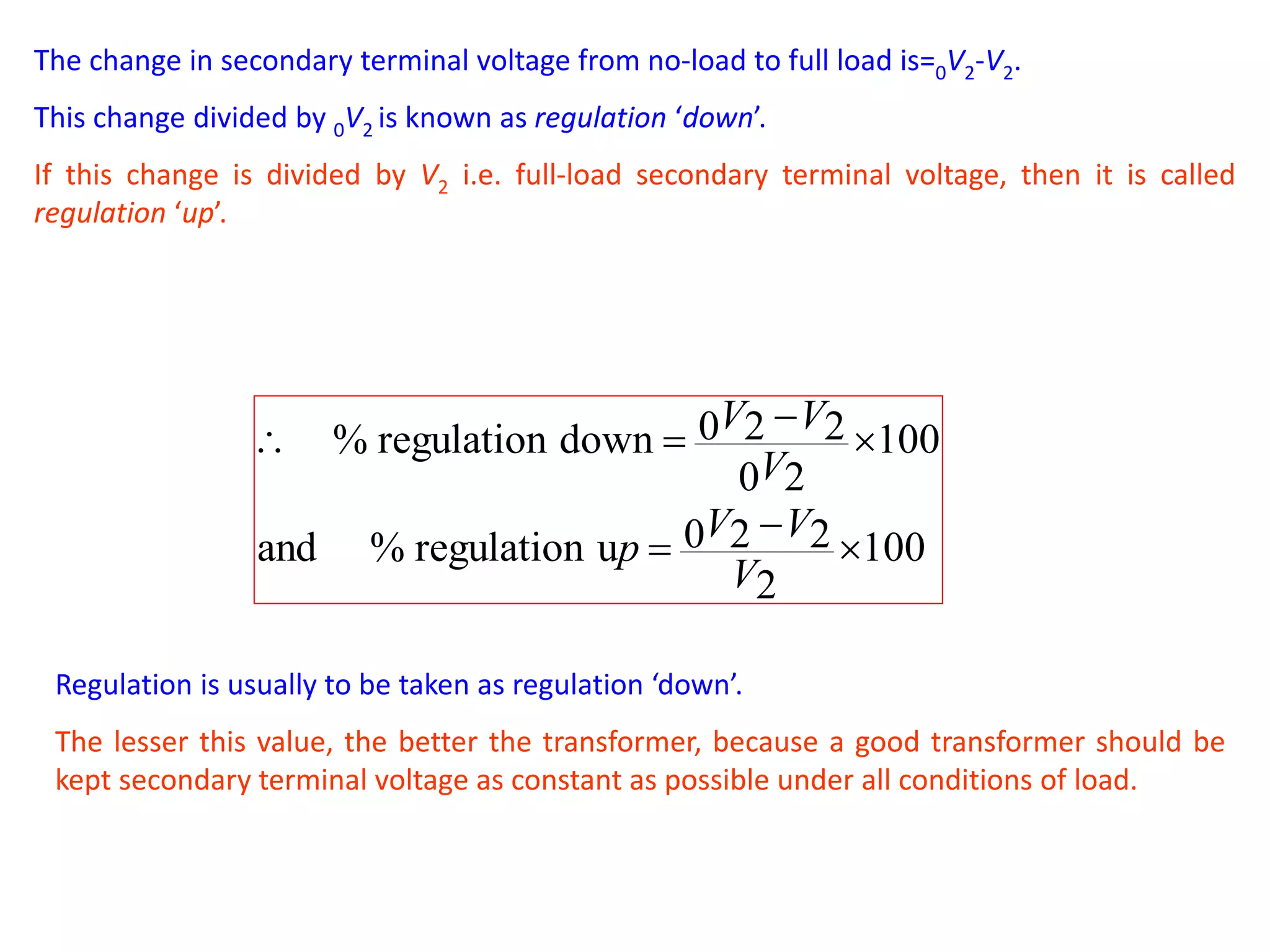
2. Regulation is defined as the percentage difference between no-load and full-load secondary terminal voltages, with regulation down using no-load voltage and regulation up using full-load voltage.
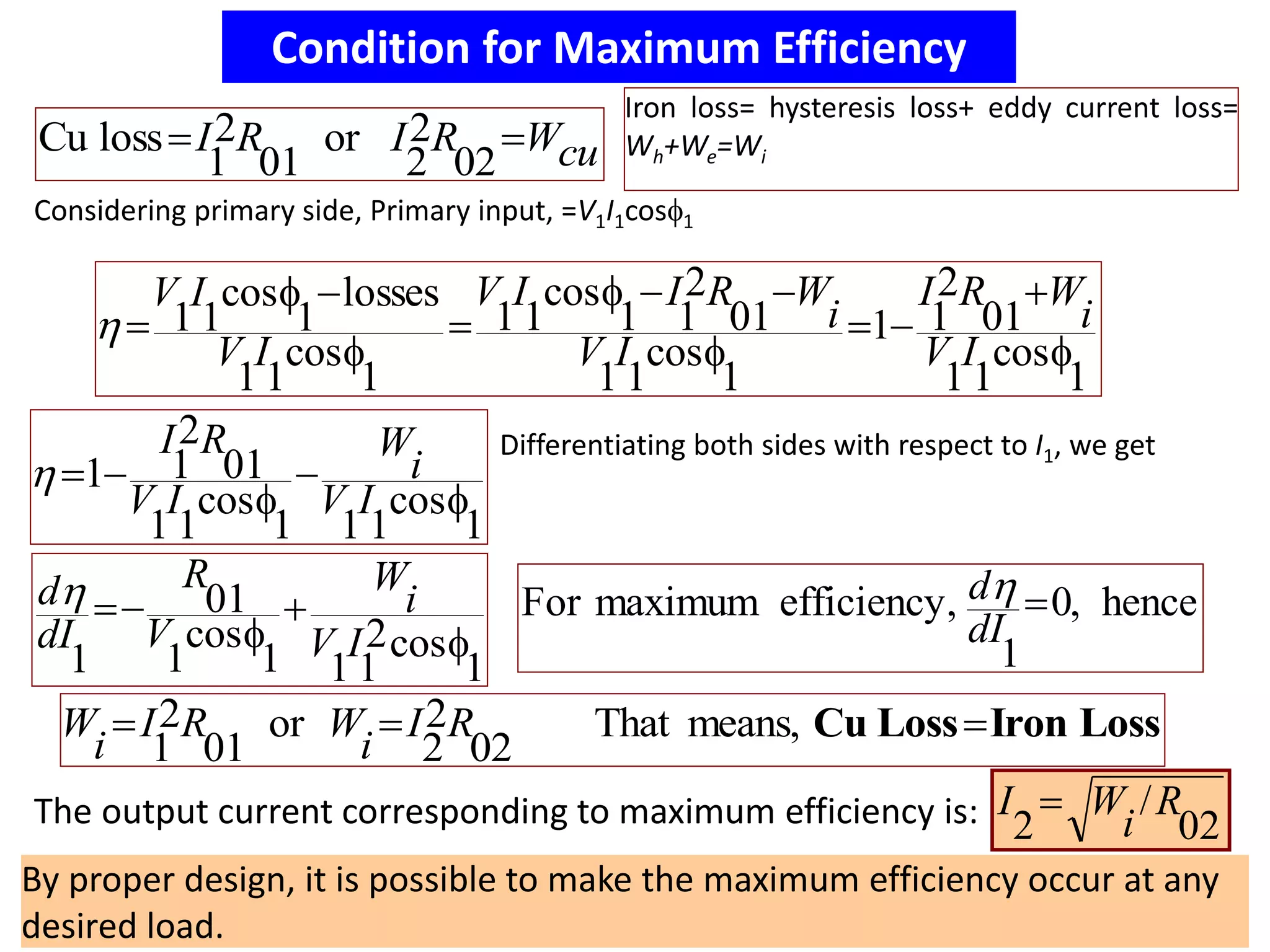
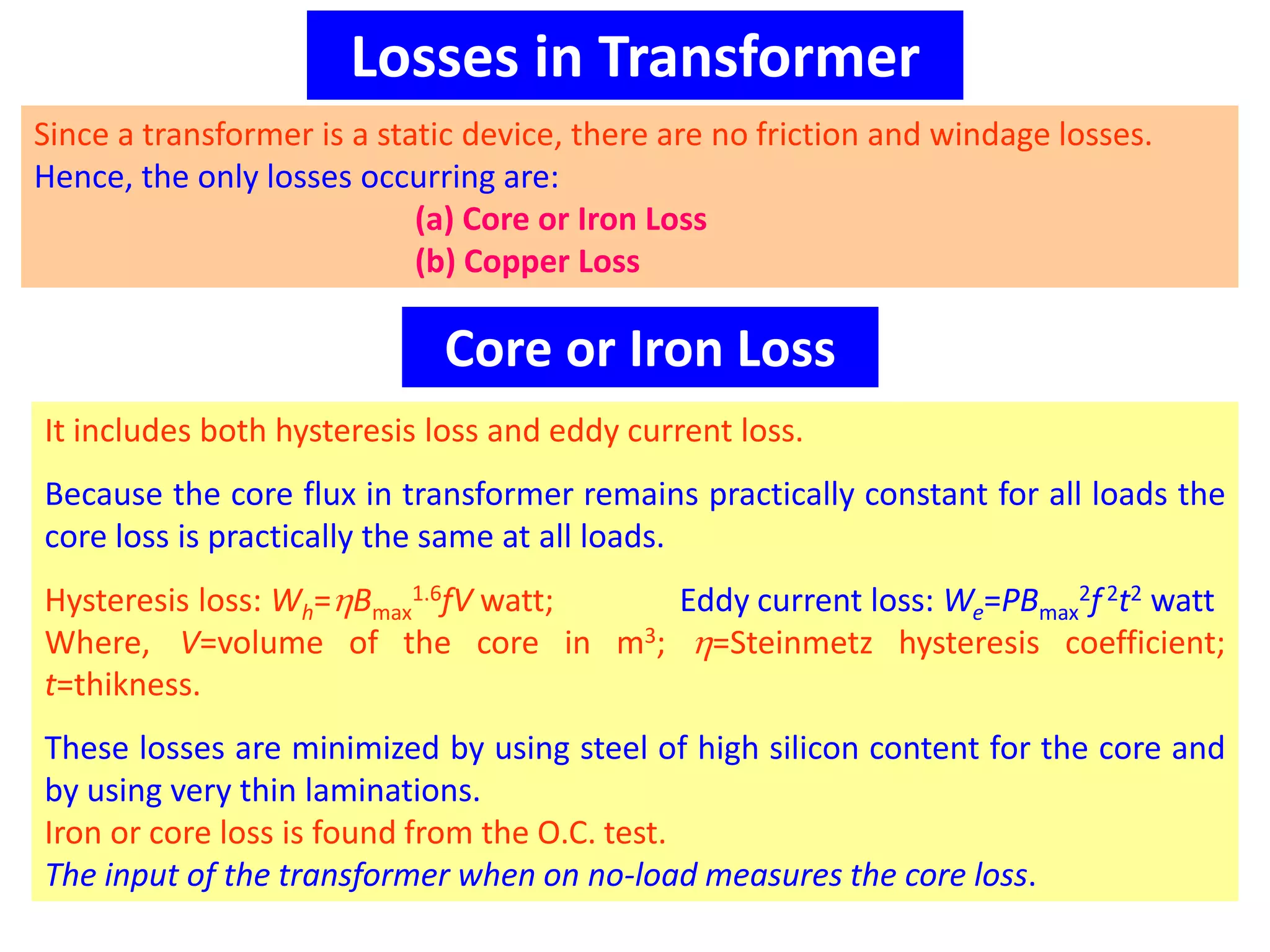
3. The main losses in transformers are core/iron loss and copper loss. Core loss is constant with load while copper loss depends on load and increases with higher load.
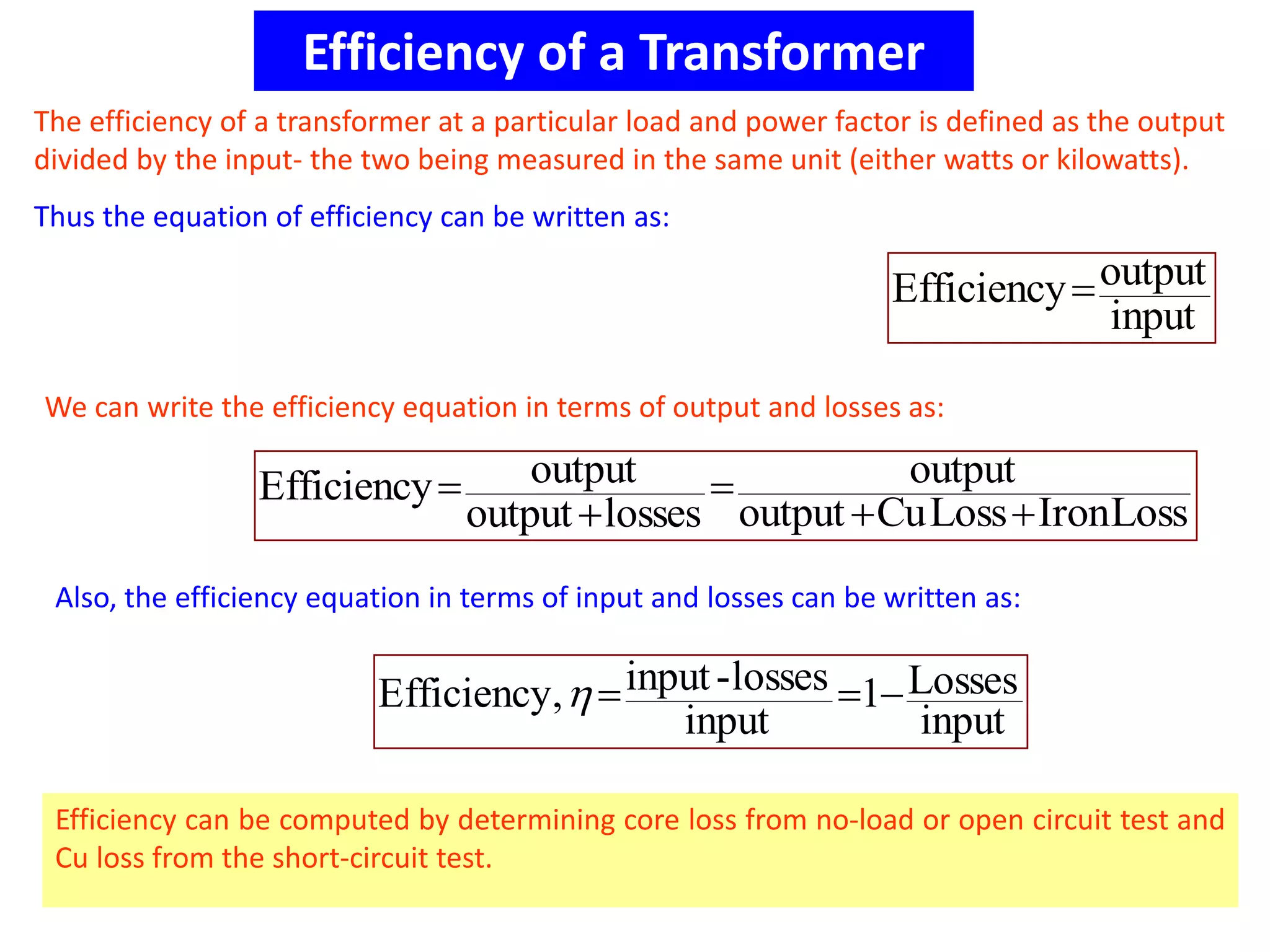
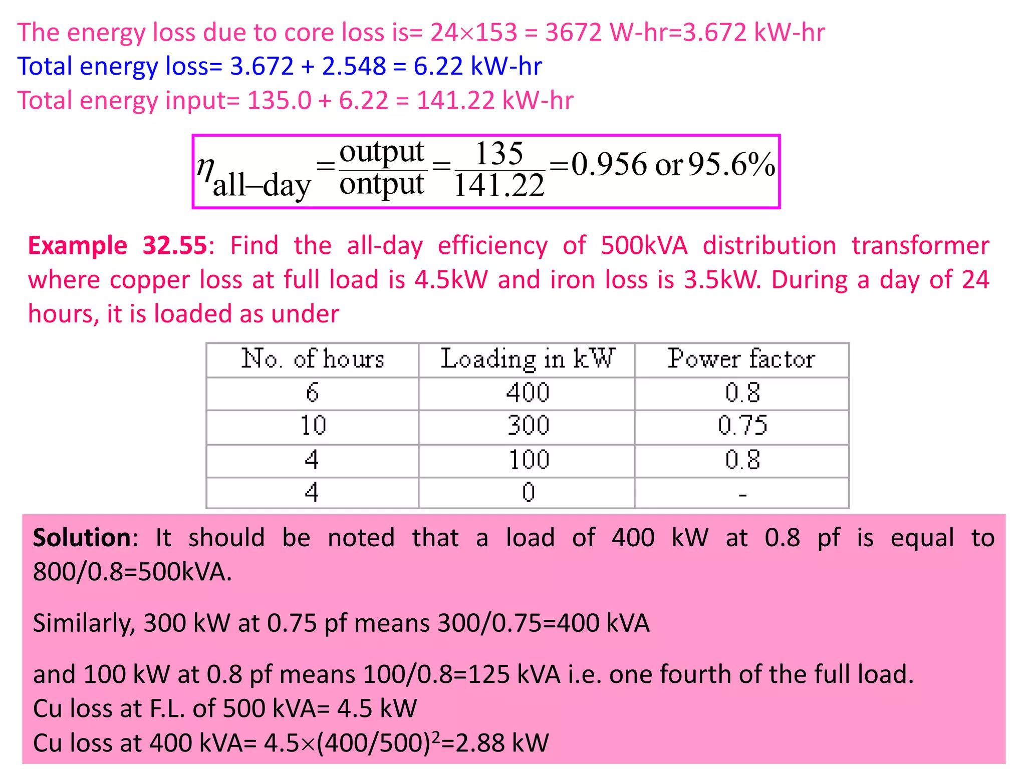
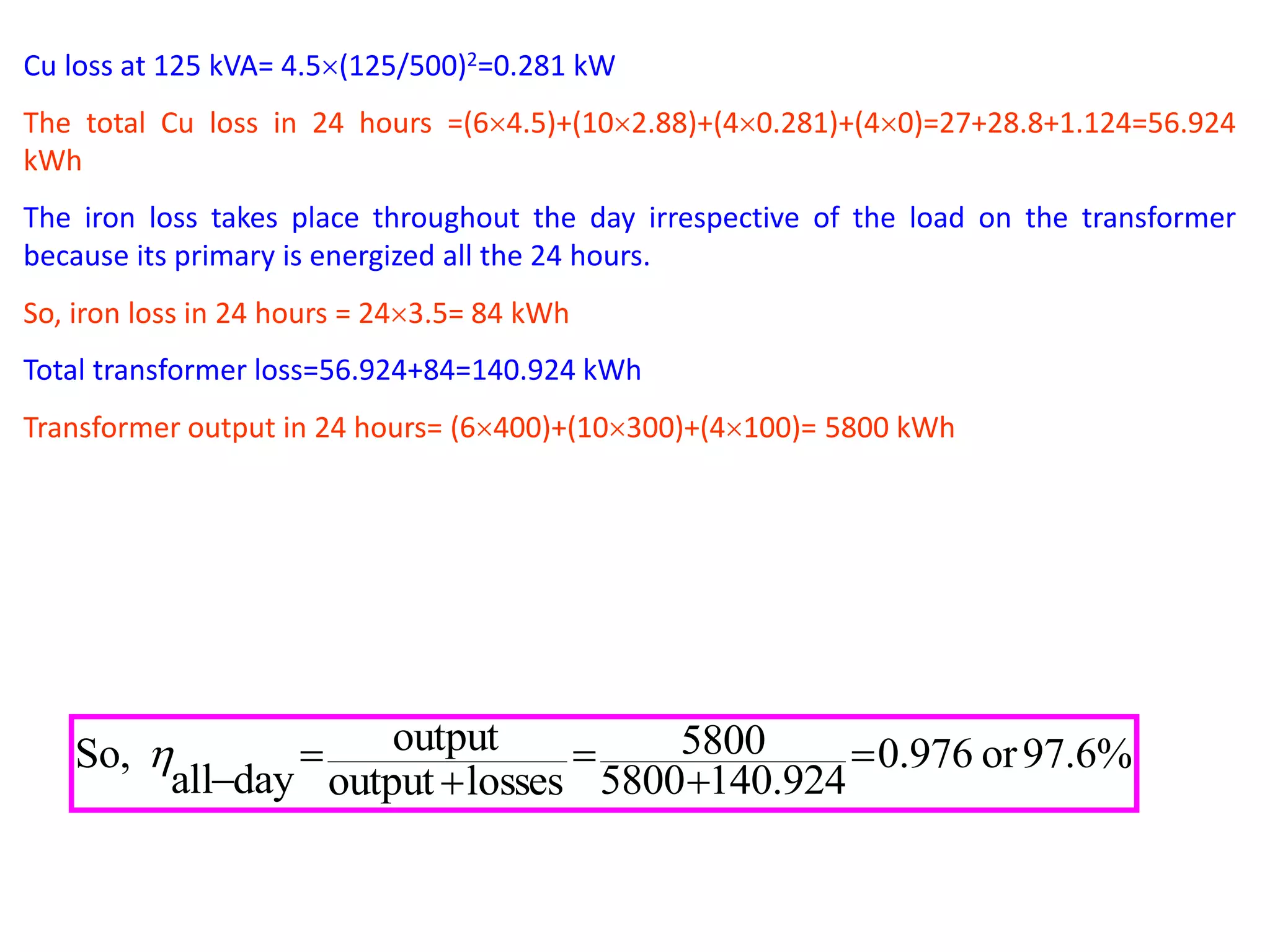
4. Efficiency is calculated based on output versus input power
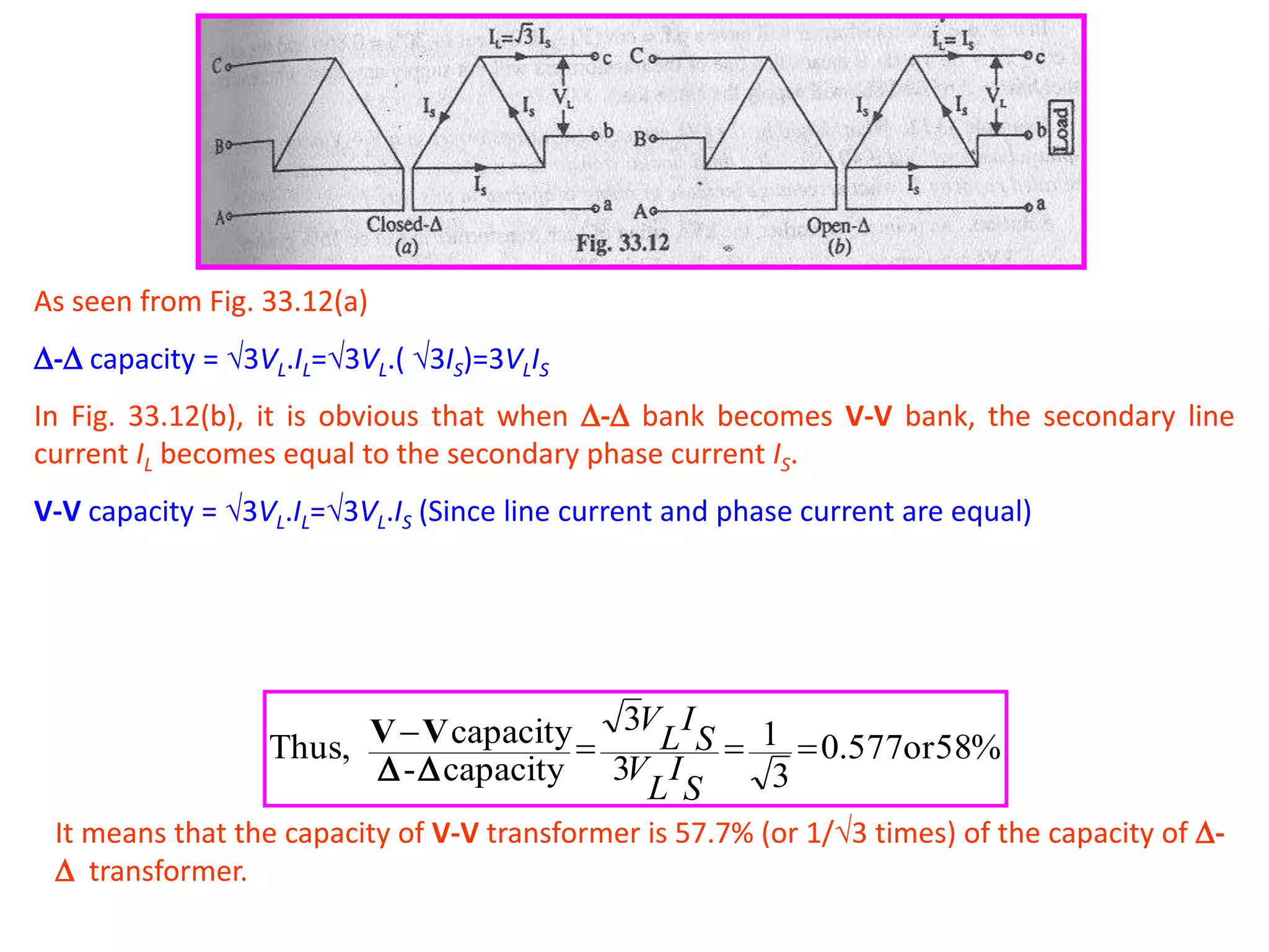
![Copper Loss
This loss is due to the ohmic resistance of the transformer windings.
Total Cu loss=I1
2R1+I2
2R2= I1
2R01=I2
2R02.
It is clear that Cu loss is proportional to (current)2 or kVA2.
So, Cu loss at half-load is one-fourth [(1/2)2=1/4] of that at full load.
Cu loss at one-quarter-load is one-sixteen [(1/4)2=1/16] of that at full load.
Cu loss at five-fourths -load is twenty five by-sixteen [(5/4)2=25/16] of that at full load.
The value of copper loss is found from the short-circuit test.](https://image.slidesharecdn.com/singleand3phasetransformer-140611015113-phpapp01/75/Single-and-3-phase-transformer-5-2048.jpg)