Content
Introduction
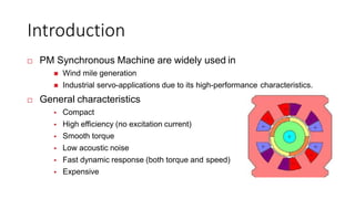
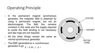
•The permanent magnet synchronous generator called so because in this synchronous generator
excitation is provided with the permanent magnet instead of the external excitation source.
•Its rotor is consists of the permanent that generates a field for excitation and replaces the external
supply source for the generator.
•In most of generation power plants, the synchronous generator is used. In steam turbines, hydro
turbines, and in gas turbines synchronous generator is used.
•Like other generators, the physical structure of this generator is the same it also consists of the rotor
which also comprises of the permanent magnet with the shaft connected with it.
•Like stator of other generators, this generator also has a stator that provides protection to internal
structure from the exterior environment.
•In permanent synchronous generator, there is no need of the slip rings and carbon brushes, which
make the machine less expensive, lightweight, and maintenance of the generator also decreases.
•But in high rating generators, large size generators are used that make machines
somewhat expensive and increases the price.
•The generator attached with the power electronic conversion circuitry can work on the
less speed and so there is no need of the gearbox.
•The presence of gearboxes increases the price, energy losses, and cost of repairing
the generator but without the gearbox price and weight of circuitry deceases but it also
the best option for the offshore applications.
•With the direction of flux lines, the permanent synchronous generator is divided into
three categories first one is the radial flux permanent magnet synchronous generator,
the second one is the axial flux permanent magnet synchronous generator and the third
one is the transverse flux permanent synchronous generator.
Permanent Magnet Technology
• The use of permanent magnets (PMs) in construction of
electrical machines
• brings the following benefits:
 No electrical energy is absorbed by the field excitation
system and thus there are no excitation losses which means
substantial increase in the efficiency,
 Higher torque and/or output power per volume than
when using electromagnetic excitation,
 Better dynamic performance than motors with
electromagnetic
• excitation (higher magnetic flux density in the air gap),
 Simplification of construction and maintenance,
 Reduction of prices for some types of machines.
Applications of Permanent Synchronous Generator
• These are some applications of the permanent magnet synchronous
generator.
• It used to provide the power for the excitation of the high rating synchronous
generator.
• During the short circuit, these generators provide the power to the generator
connected in the system to maintain the required voltage for the system.
• It also used in such power generation systems where wind turbines are used.
Permanent Magnet Classification
Permanent Magnet
Synchronous
Machine (PMSG)
Permanent
Magnet
Permanent Magnet
Brushless Machine
(BLDC)
Permanent Magnet Classification
Introduction
 PM Synchronous Machine are widely used in
 Wind mile generation
 Industrial servo-applications due to its high-performance characteristics.
 General characteristics
 Compact
 High efficiency (no excitation current)
 Smooth torque
 Low acoustic noise
 Fast dynamic response (both torque and speed)
 Expensive
Construction
PMSM
Stator Rotor
Radial Flux &
Axial Flux
Inner Rotor &
Outer Rotor
Longitudinal &
Transversal
Radial & AxialRotor
If the normal vector is perpendicular to
axis, machine is called Radial. If the
normal vector is parallel with the axis, the
machine is calledAxial.
Radial Rotor
 Higher power rating achieved by
increasing the length of machine.
 Used in
 Ship propulsion
 Robotics
 Traction
 Wind systems
Radial & AxialRotor
Axial Rotor
 Smaller than Radial machine
 High torque density
Used in
 Gearless elevator systems
 Rarely used in Traction
 Generation
Longitudinal & Transversal Rotor
In transversal flux machines, the
plane of flux path is perpendicular to
the direction of rotor motion.
Transversal flux machines can be
adjusted independently current
loading and the magnetic loading.
Used in
 Applications with high torque
density requirement.
 Free piston generators for hybrid
vehicles.
 Ship propulsion and wind system.
Inner and Outer Rotor
Inner Rotor
The interior-magnet rotor has radially
magnetized and alternately poled magnets.
Because the magnet pole area is smaller
than the pole area at the rotor surface, the
air gap flux density on open circuit is less
than the flux density in the magnet.
The magnet is very well protected against
centrifugal forces. Such a design is
recommended for high frequency high
speed motors.
Outer Rotor
The surface magnet motor can have
magnets magnetized radially or sometimes
circumferentially. An external high
conductivity non-ferromagnetic cylinder is
sometimes used. It protects the PMs against
the demagnetizing action of armature
reaction and centrifugal forces, provides an
asynchronous starting torque, and acts as a
damper.
The magnet is very well protected against
centrifugal forces. Such a design is
recommended for high frequency high
PM Configuration
PM
(Permanent
Magnet )
Surface
Magnet
Inset Magnet
Buried Magnet
Surface and Buried Magnet
•Surface Magnets
 Simple construction
 Small armature reaction flux
 Permanent magnets not
• protected against armature fields
 Eddy-current losses in
permanent magnets
 Expensive damper
Buried Magnets
 Relatively complicated
construction
 High armature reaction flux
 Permanent magnets protected
against armature fields
 No eddy-current losses in
permanent magnets
 Less expensive damper
Permanent magnet B-H curve
Operating Principle
 In the permanent magnet synchronous
generator, the magnetic field is obtained by
using a permanent magnet, but not an
electromagnet. The field flux remains
constant in this case and the supply required
to excite the field winding is not necessary
and slip rings are not required.
 All the other things remain the same as
normal synchronous generator.
 The EMF generated by a synchronous
generator is given as follows
Equivalent Circuit – rotor side
 Voltage Equation of PM machine in rotor reference
Equivalent Circuit – rotor side
Fig: PM equivalent for d-axis & q-axis
Equivalent Circuit – rotor side
 Flux Linkage equations
 The Flux Linkage can be generated field current
Vector Diagram
 Stator reference axis
 X-Y axis
 Rotor reference axis
 d-q axis

Pmsg

  • 1.
  • 2.
    Introduction •The permanent magnetsynchronous generator called so because in this synchronous generator excitation is provided with the permanent magnet instead of the external excitation source. •Its rotor is consists of the permanent that generates a field for excitation and replaces the external supply source for the generator. •In most of generation power plants, the synchronous generator is used. In steam turbines, hydro turbines, and in gas turbines synchronous generator is used. •Like other generators, the physical structure of this generator is the same it also consists of the rotor which also comprises of the permanent magnet with the shaft connected with it. •Like stator of other generators, this generator also has a stator that provides protection to internal structure from the exterior environment. •In permanent synchronous generator, there is no need of the slip rings and carbon brushes, which make the machine less expensive, lightweight, and maintenance of the generator also decreases.
  • 3.
    •But in highrating generators, large size generators are used that make machines somewhat expensive and increases the price. •The generator attached with the power electronic conversion circuitry can work on the less speed and so there is no need of the gearbox. •The presence of gearboxes increases the price, energy losses, and cost of repairing the generator but without the gearbox price and weight of circuitry deceases but it also the best option for the offshore applications. •With the direction of flux lines, the permanent synchronous generator is divided into three categories first one is the radial flux permanent magnet synchronous generator, the second one is the axial flux permanent magnet synchronous generator and the third one is the transverse flux permanent synchronous generator.
  • 4.
    Permanent Magnet Technology •The use of permanent magnets (PMs) in construction of electrical machines • brings the following benefits:  No electrical energy is absorbed by the field excitation system and thus there are no excitation losses which means substantial increase in the efficiency,  Higher torque and/or output power per volume than when using electromagnetic excitation,  Better dynamic performance than motors with electromagnetic • excitation (higher magnetic flux density in the air gap),  Simplification of construction and maintenance,  Reduction of prices for some types of machines.
  • 5.
    Applications of PermanentSynchronous Generator • These are some applications of the permanent magnet synchronous generator. • It used to provide the power for the excitation of the high rating synchronous generator. • During the short circuit, these generators provide the power to the generator connected in the system to maintain the required voltage for the system. • It also used in such power generation systems where wind turbines are used.
  • 6.
    Permanent Magnet Classification PermanentMagnet Synchronous Machine (PMSG) Permanent Magnet Permanent Magnet Brushless Machine (BLDC)
  • 7.
  • 8.
    Introduction  PM SynchronousMachine are widely used in  Wind mile generation  Industrial servo-applications due to its high-performance characteristics.  General characteristics  Compact  High efficiency (no excitation current)  Smooth torque  Low acoustic noise  Fast dynamic response (both torque and speed)  Expensive
  • 9.
    Construction PMSM Stator Rotor Radial Flux& Axial Flux Inner Rotor & Outer Rotor Longitudinal & Transversal
  • 10.
    Radial & AxialRotor Ifthe normal vector is perpendicular to axis, machine is called Radial. If the normal vector is parallel with the axis, the machine is calledAxial. Radial Rotor  Higher power rating achieved by increasing the length of machine.  Used in  Ship propulsion  Robotics  Traction  Wind systems
  • 11.
    Radial & AxialRotor AxialRotor  Smaller than Radial machine  High torque density Used in  Gearless elevator systems  Rarely used in Traction  Generation
  • 12.
    Longitudinal & TransversalRotor In transversal flux machines, the plane of flux path is perpendicular to the direction of rotor motion. Transversal flux machines can be adjusted independently current loading and the magnetic loading. Used in  Applications with high torque density requirement.  Free piston generators for hybrid vehicles.  Ship propulsion and wind system.
  • 13.
  • 14.
    Inner Rotor The interior-magnetrotor has radially magnetized and alternately poled magnets. Because the magnet pole area is smaller than the pole area at the rotor surface, the air gap flux density on open circuit is less than the flux density in the magnet. The magnet is very well protected against centrifugal forces. Such a design is recommended for high frequency high speed motors.
  • 15.
    Outer Rotor The surfacemagnet motor can have magnets magnetized radially or sometimes circumferentially. An external high conductivity non-ferromagnetic cylinder is sometimes used. It protects the PMs against the demagnetizing action of armature reaction and centrifugal forces, provides an asynchronous starting torque, and acts as a damper. The magnet is very well protected against centrifugal forces. Such a design is recommended for high frequency high
  • 16.
  • 17.
    Surface and BuriedMagnet •Surface Magnets  Simple construction  Small armature reaction flux  Permanent magnets not • protected against armature fields  Eddy-current losses in permanent magnets  Expensive damper Buried Magnets  Relatively complicated construction  High armature reaction flux  Permanent magnets protected against armature fields  No eddy-current losses in permanent magnets  Less expensive damper
  • 18.
  • 19.
    Operating Principle  Inthe permanent magnet synchronous generator, the magnetic field is obtained by using a permanent magnet, but not an electromagnet. The field flux remains constant in this case and the supply required to excite the field winding is not necessary and slip rings are not required.  All the other things remain the same as normal synchronous generator.  The EMF generated by a synchronous generator is given as follows
  • 20.
    Equivalent Circuit –rotor side  Voltage Equation of PM machine in rotor reference
  • 21.
    Equivalent Circuit –rotor side Fig: PM equivalent for d-axis & q-axis
  • 22.
    Equivalent Circuit –rotor side  Flux Linkage equations  The Flux Linkage can be generated field current
  • 23.
    Vector Diagram  Statorreference axis  X-Y axis  Rotor reference axis  d-q axis