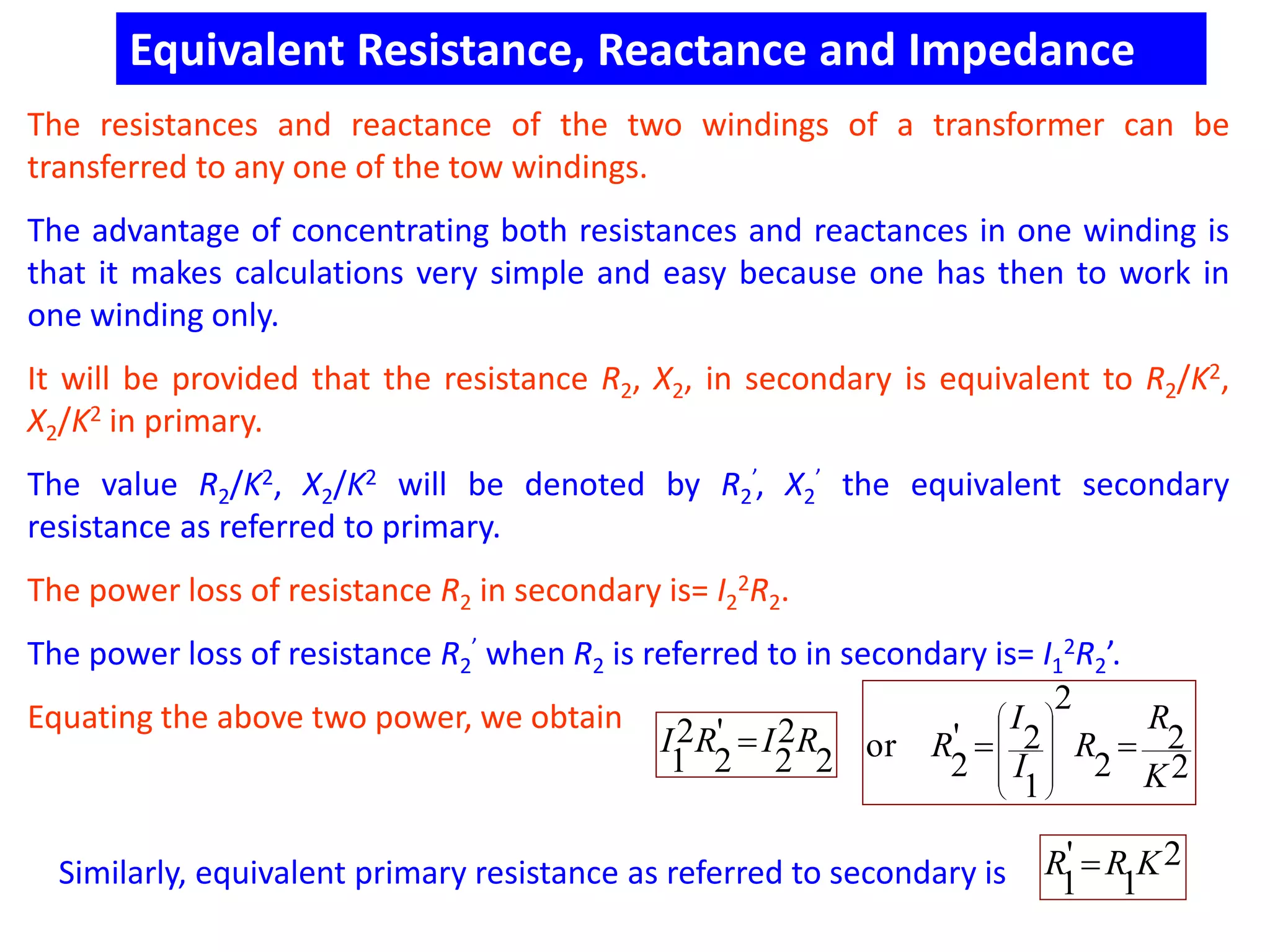
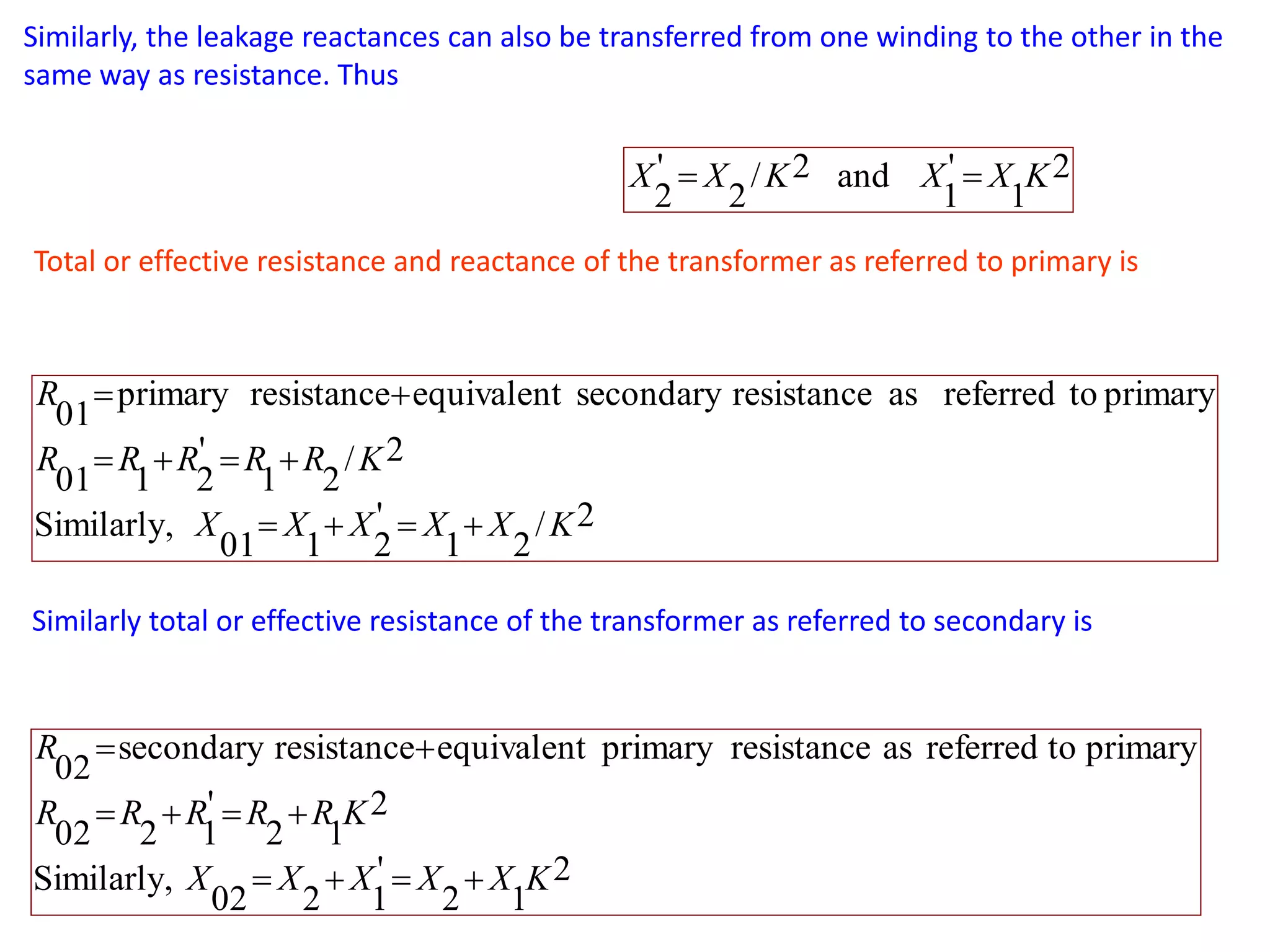
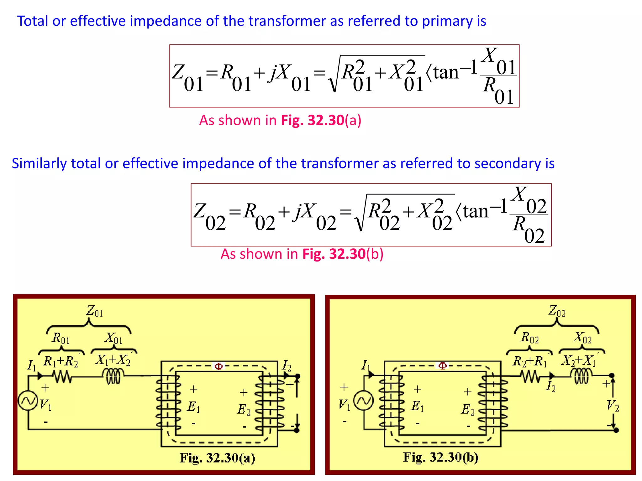
1) The equivalent resistance, reactance, and impedance of the transformer windings can be transferred from one winding to the other to simplify calculations. This is done by dividing the secondary values by the transformer ratio (K).
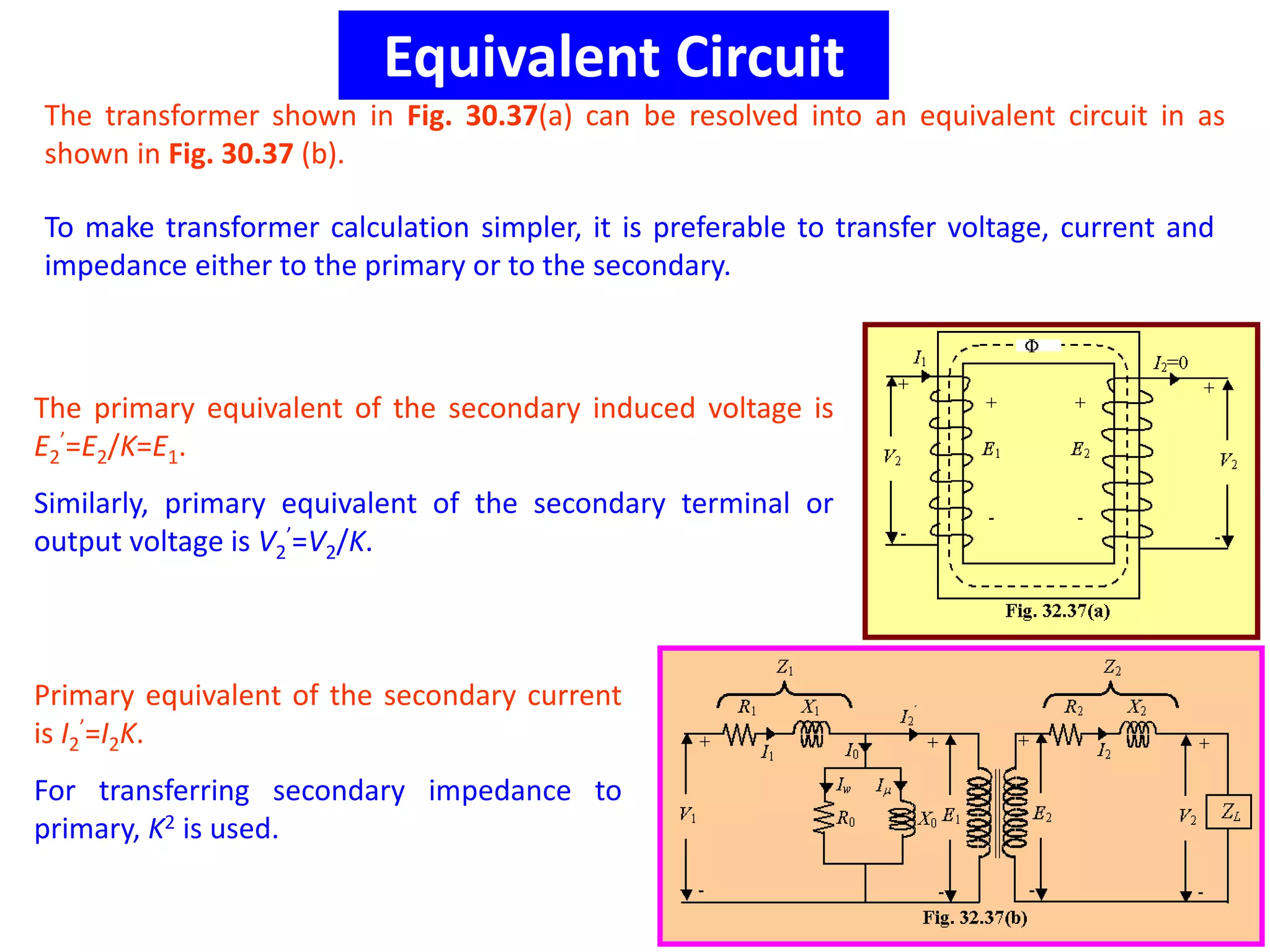
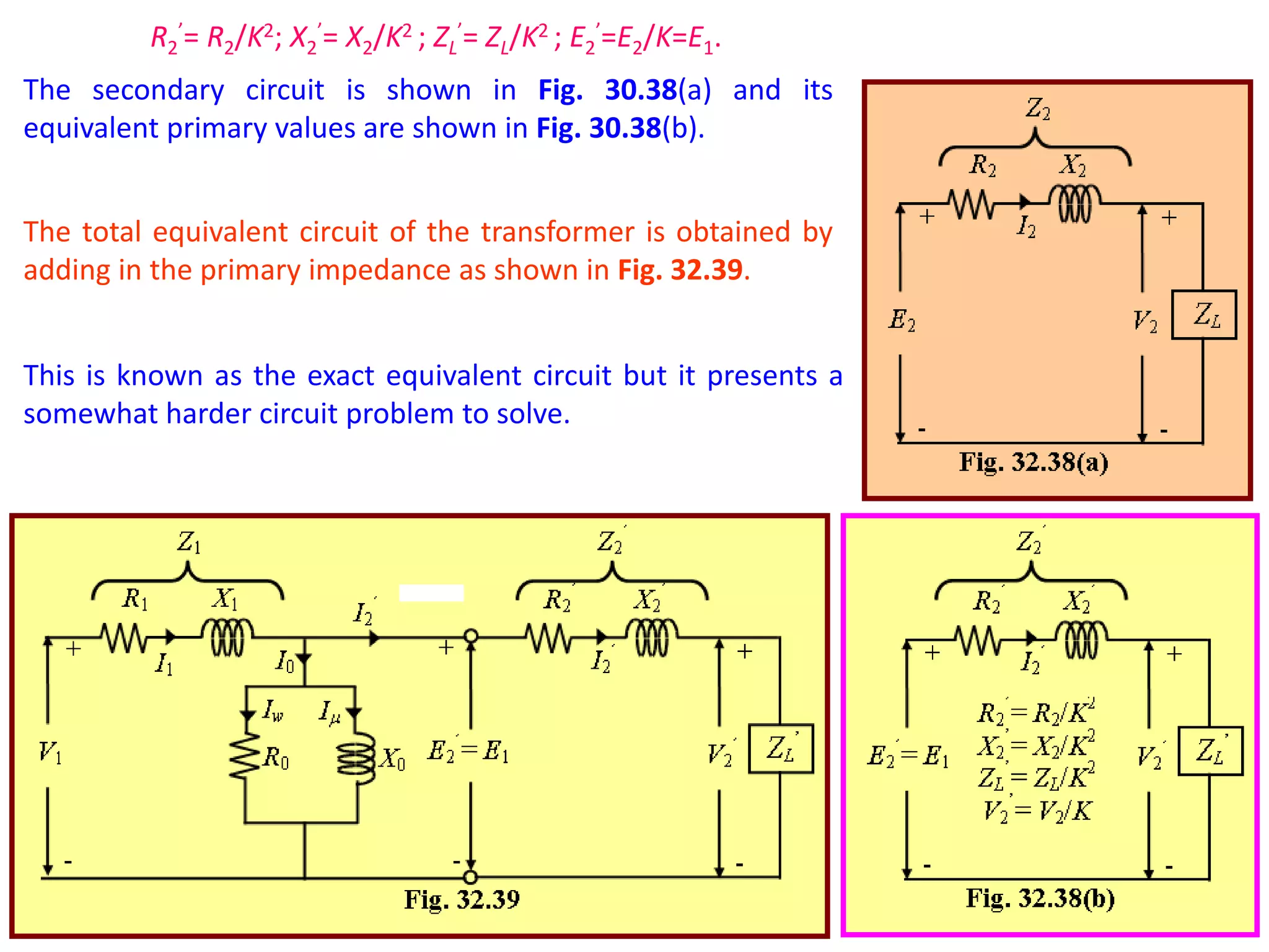
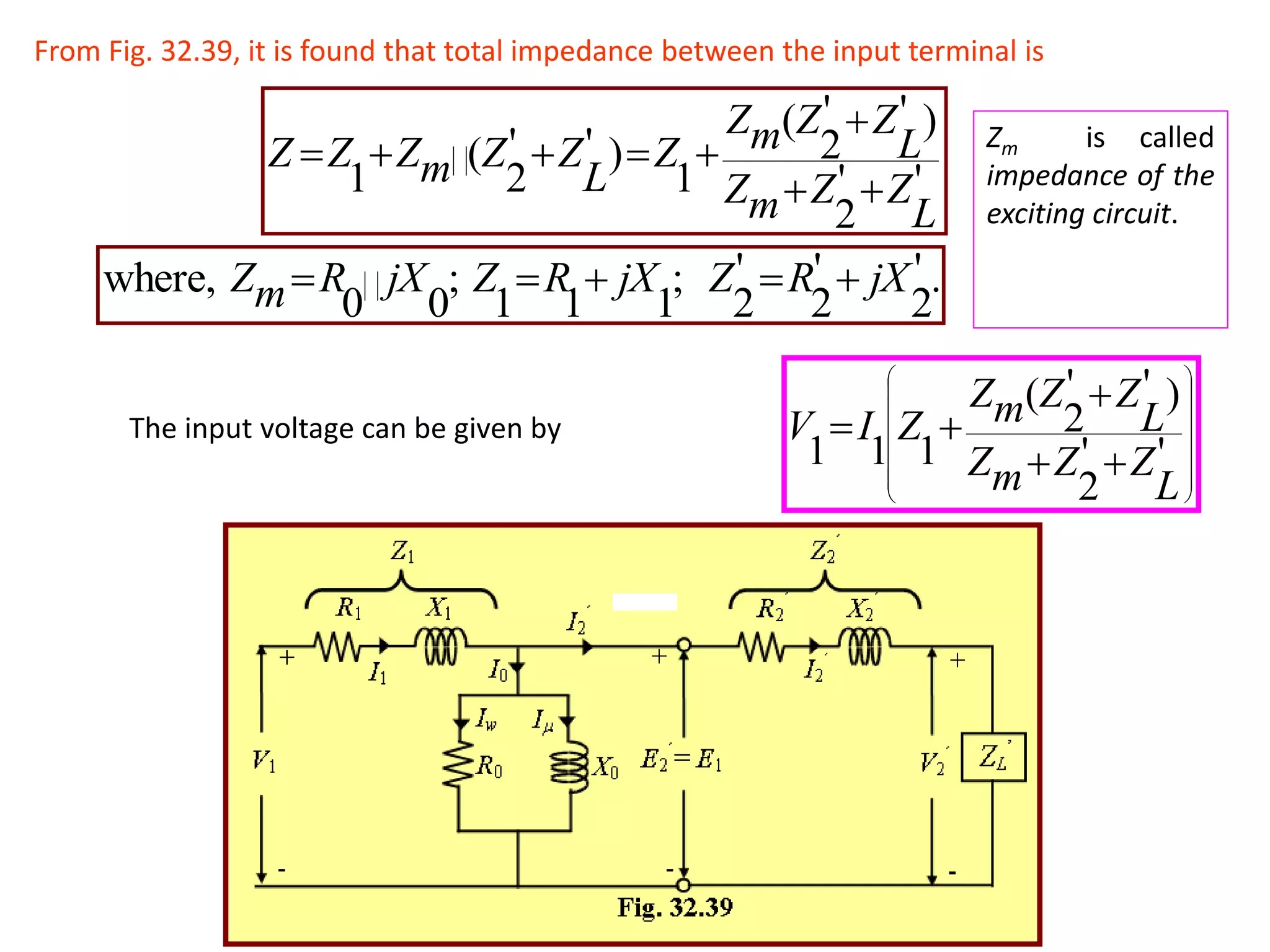
2) The equivalent circuit model represents the transformer using resistances and reactances for both the primary and secondary windings referred to a single winding for simplicity. Additional impedances are included for the magnetizing current.
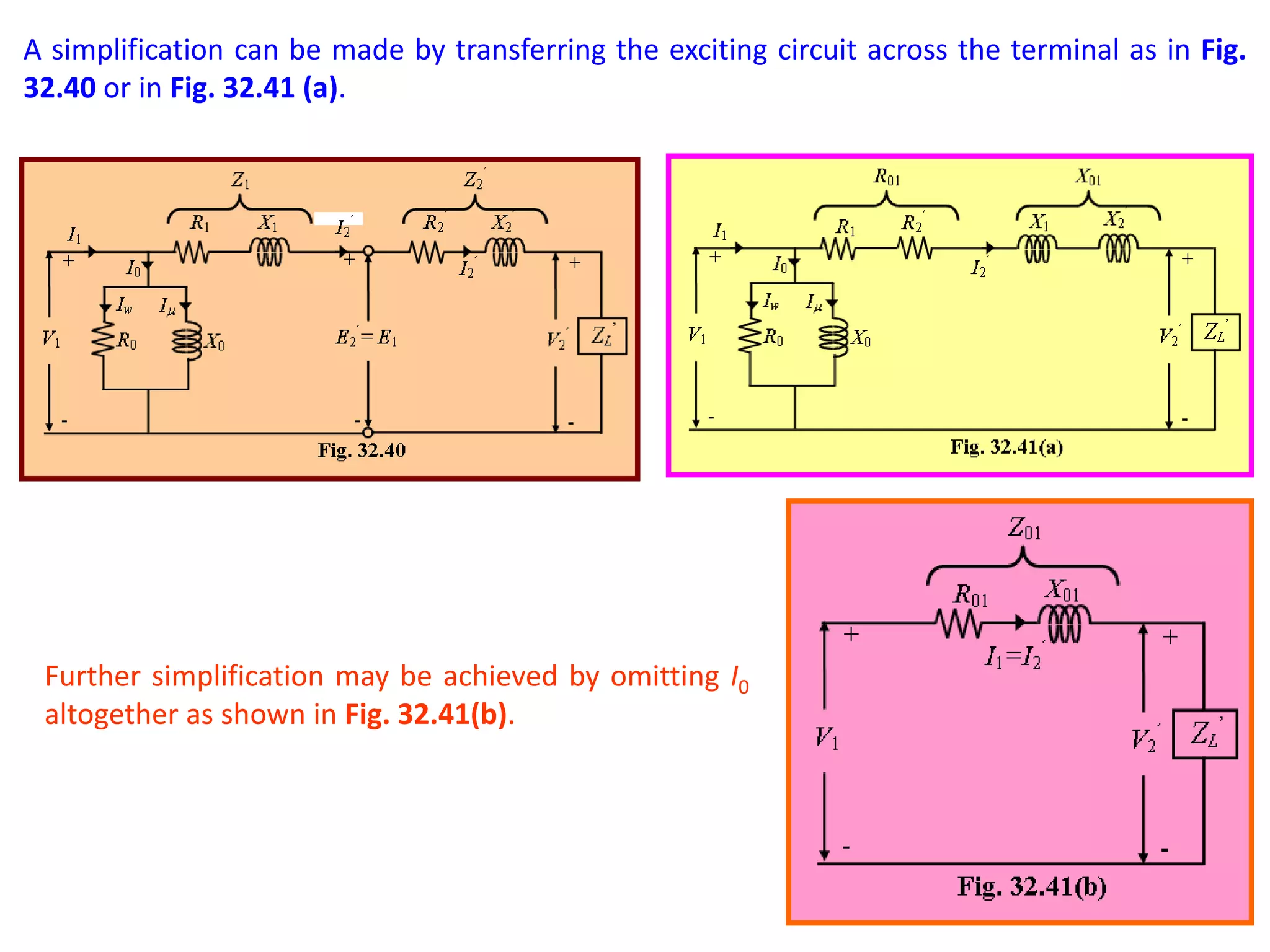
3) Simplified equivalent circuits omit some components like the magnetizing current to make the circuit problems easier to solve while still capturing the essential transformer behavior.


![[LECTURE - 01 & 02] Equivalent Circuit P](https://cdn.slidesharecdn.com/ss_thumbnails/lec-0102equivalentcircuit-241104145204-d52809f3-thumbnail.jpg?width=640&height=640&fit=bounds)


