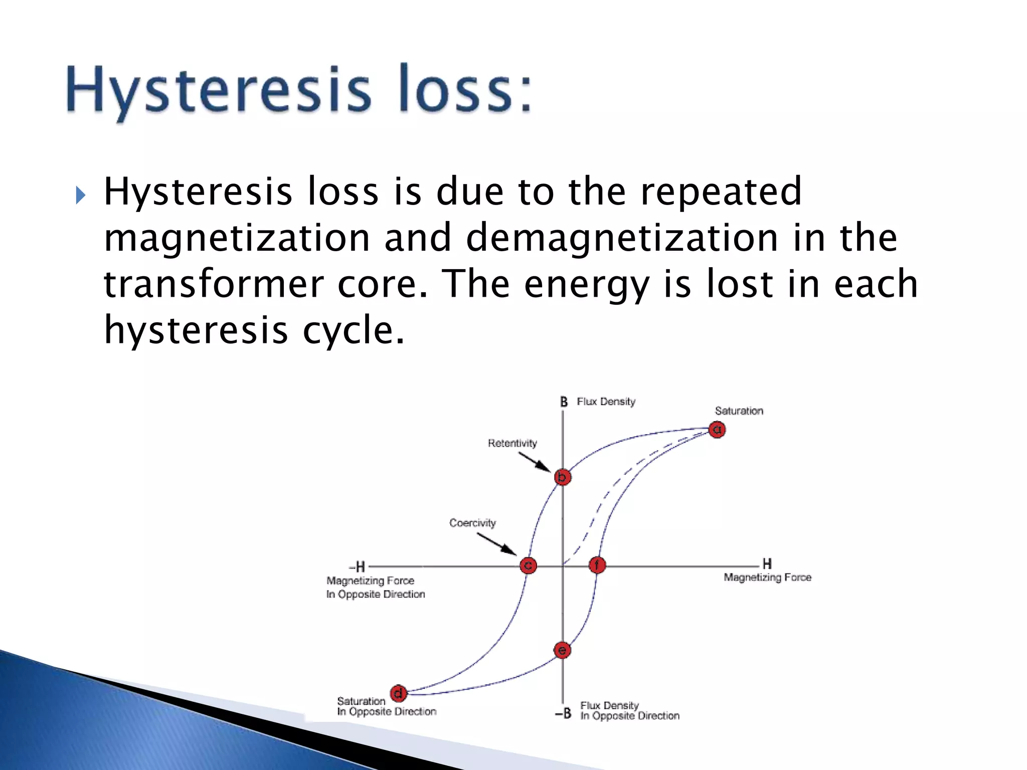
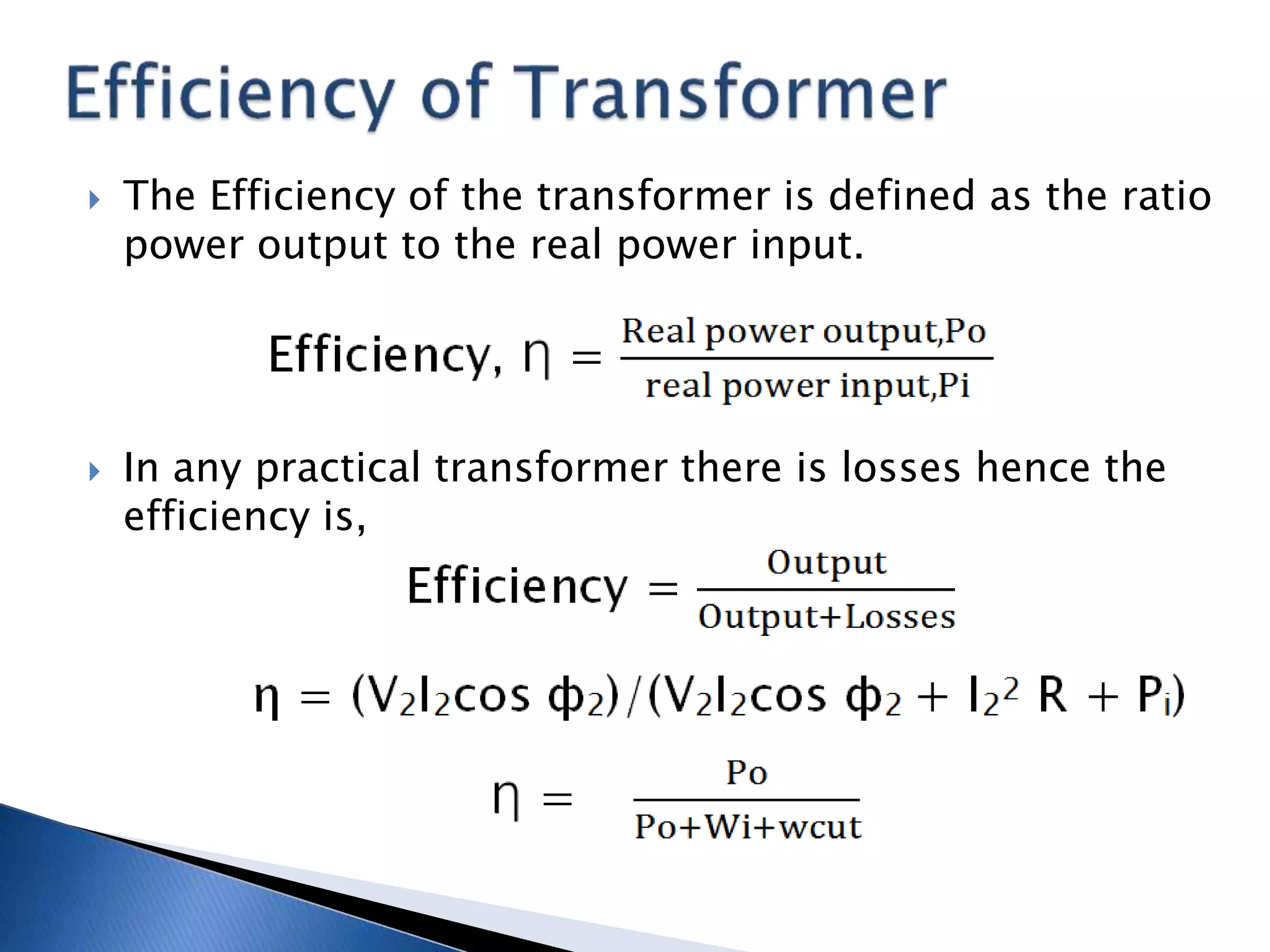
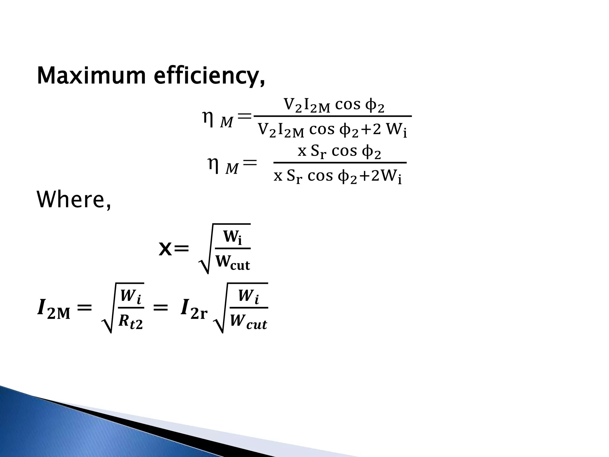
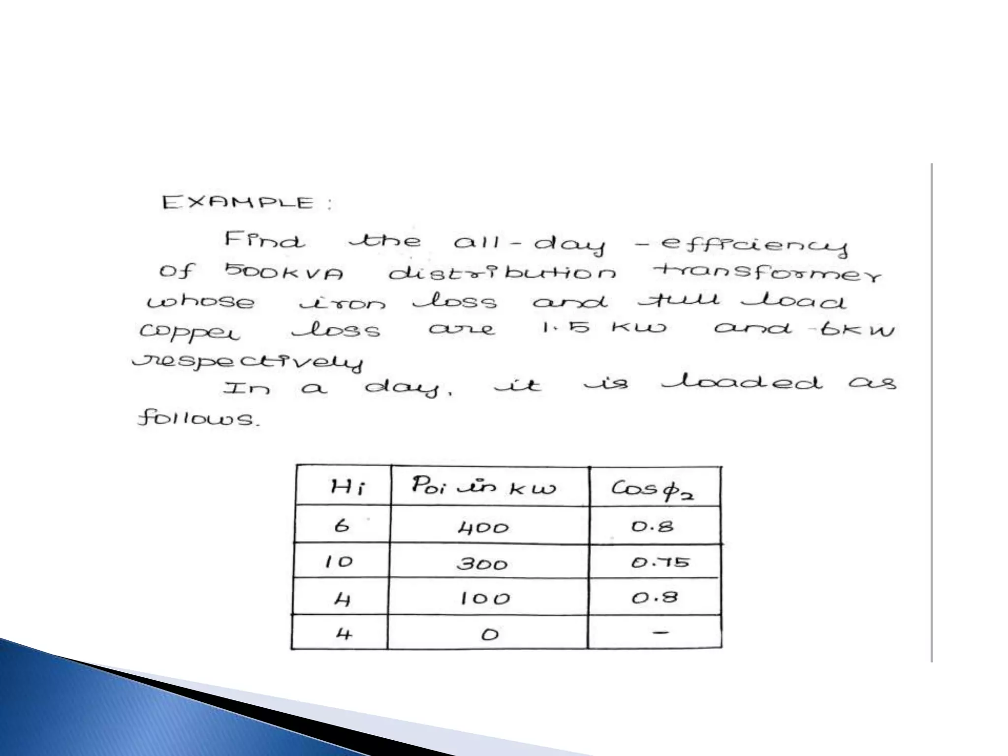
Nithyapriya. S
Prashanna.R
Praveen kumar .S
Preethi.A
Sathish Kumar.S
Shagari
 Losses in transformer
 Efficiency
 Condition for maximum efficiency
 Separation of losses
 Separation of iron loss
 All-day efficiency.
 In any electrical machine, 'loss' can be
defined as the difference between input
power and output power.
 An electrical transformer is an static device,
hence mechanical losses (like windage or
friction losses) are absent in it.
 A transformer only consists of electrical
losses (iron losses and copper losses).
 All these losses in the transformer are
dissipated in the form of heat.
 Copper loss is due to power wasted in the
form of I2R, , where ‘I’ is the current passing
through the windings and R is the internal
resistance of the windings(primary and
secondary).
 It is clear that Cu loss is proportional to
square of the current, and current depends
on the load. Hence copper loss in transformer
varies with the load.
 Hence it is also called as variable loss.
Wcut= I2
pRp + I2
sRs
 These losses occur in the core of the
transformer and are generated due to the
variations in the flux.
 They depend upon the magnetic properties of
the material used for the construction of
core. Hence these losses are also known as
core losses or iron losses (Wi).
 In transformer, the leakage magnetic flux linked with
the conducting parts like steel core or iron body of
the transformer, which will result in induced emf in
those parts, causing small circulating current in them.
We= CeBm
2 *f2
 This current is called as eddy current. Due to these
eddy currents, some energy will be dissipated in the
form of heat.
 Lamination of core material can reduce eddy current
loss.
 Hysteresis loss is due to the repeated
magnetization and demagnetization in the
transformer core. The energy is lost in each
hysteresis cycle.
 This loss depends upon the volume and
grade of the iron, frequency of magnetic
reversals and value of flux density. It can be
given by,
Wh=Ch(Bm)1.6 *f (watts)
 soft magnetic materials with low hysteresis
such as silicon steel and CRGO Steel are
usually used in core to reduce the loss .
 The total core loss is,
Wi= Wh+We
Wi= Ch(Bm)1.6 *f + CeBm
2 *f2
 The stray losses is due to the presence of
leakage field including eddy currents in tank
walls and conductors.
 The winding of the transformer should be
designed such a way to minimize the stray
loss this is achieved by splitting of
conductors into small strips to reduce eddy
current loss.
 Dielectric loss occurs in the insulating
material of the transformer that is in the oil
of the transformer, or in the solid insulations.
 When the oil gets deteriorated or the solid
insulation get damaged, or its quality
decreases and because of this, the efficiency
of transformer is effected.
 The percentage of these losses are very small
as compared to the iron and copper losses so
they can be neglected.
 The Efficiency of the transformer is defined as the ratio
power output to the real power input.
 In any practical transformer there is losses hence the
efficiency is,
 In terms of input and losses the efficiency
can be written as
 Where power output,
Po = xSrcosф2
 Total losses , Wt = Wi+

 Thus the efficiency of transformer can be
written as
 Transformer efficiency
𝜂 =
𝐱 𝑺 𝒓 𝐜𝐨𝐬 𝝓 𝟐
𝐱 𝑺 𝒓 𝐜𝐨𝐬 𝝓 𝟐+𝑾 𝒊+ 𝒙 𝟐 𝑾 𝒄𝒖𝒕
------- (1)
At maximum efficiency,
𝒅𝛈
𝒅𝒙
= 0;
𝒅 𝟐 𝛈
𝒅𝒙 𝟐< 0;
From 1,
𝒅𝛈
𝒅𝒙
=
𝑺 𝒓 𝐜𝐨𝐬 𝝓 𝟐(𝑾 𝒊 −𝒙 𝟐 𝑾 𝒄𝒖𝒕)
( 𝐱 𝑺 𝒓 𝐜𝐨𝐬 𝝓 𝟐+𝑾 𝒊+ 𝒙 𝟐 𝑾 𝒄𝒖𝒕) 𝟐
𝒅𝛈
𝒅𝒙
= 0  𝑊𝑖 − 𝑥2 𝑊𝑐𝑢𝑡 = 0
𝐖𝐢 = 𝐱 𝟐
𝐖𝐜𝐮𝐭 ---- (2)
The efficiency of a transformer for a given
power factor is maximum when the variable
copper loss is equal to the constant iron loss.
Wcut = I2r
2
Rt2 = I1r
2
Rt1
From (2)
x=
𝐖𝐢
𝐖𝐜𝐮𝐭
𝑾𝒊 = 𝒙 𝟐
𝑰 𝟐𝐫
𝟐
𝑹 𝒕𝟐
𝑾𝒊 = 𝑰 𝟐𝐌
𝟐
𝑹 𝒕𝟐
Current at maximum efficiency,
𝑰 𝟐𝐌 =
𝑾 𝒊
𝑹 𝒕𝟐
= 𝑰 𝟐𝐫
𝑾 𝒊
𝑾 𝒄𝒖𝒕
𝑰 𝟏𝑴 =
𝑾 𝒊
𝑹 𝒕𝟏
= 𝑰 𝟏𝐫
𝑾 𝒊
𝑾 𝒄𝒖𝒕
kVA at maximum efficiency
𝑺 𝐌 = 𝑺 𝒓
𝑾 𝒊
𝑾 𝒄𝒖𝒕
Maximum efficiency,
η 𝑀=
V2I2M cos ϕ2
V2I2M cos ϕ2+2 Wi
η 𝑀=
x Sr cos ϕ2
x Sr cos ϕ2+2Wi
Where,
x=
𝐖𝐢
𝐖𝐜𝐮𝐭
𝑰 𝟐𝐌 =
𝑾 𝒊
𝑹 𝒕𝟐
= 𝑰 𝟐𝐫
𝑾 𝒊
𝑾 𝒄𝒖𝒕
𝜂 =
𝑥 𝑆 𝑟 𝑐𝑜𝑠 𝜙2
𝑥 𝑆 𝑟 𝑐𝑜𝑠 𝜙2+𝑊 𝑖+ 𝑥2 𝑊𝑐𝑢𝑡
x= constant. Hence, 𝑊𝑖 + 𝑥2 𝑊𝑐𝑢𝑡 = k
𝜂 =
𝑥 𝑆 𝑟 𝑐𝑜𝑠 𝜙2
𝑥 𝑆 𝑟 𝑐𝑜𝑠 𝜙2+𝑘
𝜂 =
1
1+
𝑘
𝑥 𝑆 𝑟 𝑐𝑜𝑠 𝜙2
At Maximium effieciency , 𝟏 +
𝒌
𝒙 𝑺 𝒓 𝒄𝒐𝒔 𝝓 𝟐
is minimum, i.e
when 𝑐𝑜𝑠 𝜙2 is maximum.
Hence, for a constant load current, maximum efficiency
occurs when the load power factor is unity. (i.e, resistive load).
 The iron loss is separated into its corresponding compenents as
Iron loss =Wi=Wh+We
 Where Hysteresis loss, Wh= Ch Bm
1.6f W
 Eddy current loss, We = CeBm
2f 2 W
 Now
Wi =ChB f +CeB f2
 Where
Wh=hysteresis loss W
We=eddy current loss W
Bm=magnetic flux intensity T
ChB=hysteresis loss constant(value of y-intercept in the
graph)
CeB=eddy current loss constant(value of slope in the graph)
ALL DAY EFFICIENCY
• Computing efficiency by taking the ratio of RAM power output
by real power input best judges the performance of power
transformers which are energised only during load conditions.
• The loads connected to power transformers are normally at
constant level around full-load.
• Distribution Transformers are installed by Electric Board Power
Grid are kept energied for all the twenty four hours a day, seven
days a week and 52 weeks a year.
 The loads connected to such transformer keep on
changing from time to time.
 In a day of 24 hrs , such distribution transformer
are subjected to full load hardly for about 4-5 hrs.
 In remaining period they are only partly loaded .
Sometimes they are on no-load.
 This means that iron-loss is incurred at constant
level for all 24 hrs while copper losses incurred in
the transformer keep on changing with respect to
change in load condition.
 Therefore the performance of distribution
transformer by taking into account the enery
delivered and energy consumed by it for all the
24 hrs in a day.
 DEFINITION:
 All day efficiency, of the transformer is defined
as the ratio of energy delivered by the
transformer for 24 hrs in a day to the energy
consumed by the transformer from supply
system for the same period.

 All - day efficiency =
𝐸𝑛𝑒𝑟𝑔𝑦 𝑑𝑒𝑙𝑖𝑣𝑒𝑟𝑑,𝑘𝑊𝐻𝑜
Energy consumed,kWHi
*24
 To have high All-day efficiency, distribution
Transformers are designed and constructed with
(I)low iron losses and (ii) the load at which
maximum efficiency occurs.
 Wi ---> iron loss
 Wcut ---> Full load copper loss.
 Energy output kWHo = ∑Xi Sr Cos𝛟2 X Hi
 Energy input kWHi = energy output + energy to
meet losses.
kWHi = kWH0+ ( 24*Wi)+(∑ X2
i
WcutHi )
TRANSFORMERS and LOSSES

TRANSFORMERS and LOSSES

  • 2.
    Nithyapriya. S Prashanna.R Praveen kumar.S Preethi.A Sathish Kumar.S Shagari
  • 3.
     Losses intransformer  Efficiency  Condition for maximum efficiency  Separation of losses  Separation of iron loss  All-day efficiency.
  • 4.
     In anyelectrical machine, 'loss' can be defined as the difference between input power and output power.  An electrical transformer is an static device, hence mechanical losses (like windage or friction losses) are absent in it.  A transformer only consists of electrical losses (iron losses and copper losses).  All these losses in the transformer are dissipated in the form of heat.
  • 6.
     Copper lossis due to power wasted in the form of I2R, , where ‘I’ is the current passing through the windings and R is the internal resistance of the windings(primary and secondary).  It is clear that Cu loss is proportional to square of the current, and current depends on the load. Hence copper loss in transformer varies with the load.  Hence it is also called as variable loss. Wcut= I2 pRp + I2 sRs
  • 7.
     These lossesoccur in the core of the transformer and are generated due to the variations in the flux.  They depend upon the magnetic properties of the material used for the construction of core. Hence these losses are also known as core losses or iron losses (Wi).
  • 8.
     In transformer,the leakage magnetic flux linked with the conducting parts like steel core or iron body of the transformer, which will result in induced emf in those parts, causing small circulating current in them. We= CeBm 2 *f2  This current is called as eddy current. Due to these eddy currents, some energy will be dissipated in the form of heat.  Lamination of core material can reduce eddy current loss.
  • 9.
     Hysteresis lossis due to the repeated magnetization and demagnetization in the transformer core. The energy is lost in each hysteresis cycle.
  • 10.
     This lossdepends upon the volume and grade of the iron, frequency of magnetic reversals and value of flux density. It can be given by, Wh=Ch(Bm)1.6 *f (watts)  soft magnetic materials with low hysteresis such as silicon steel and CRGO Steel are usually used in core to reduce the loss .  The total core loss is, Wi= Wh+We Wi= Ch(Bm)1.6 *f + CeBm 2 *f2
  • 11.
     The straylosses is due to the presence of leakage field including eddy currents in tank walls and conductors.  The winding of the transformer should be designed such a way to minimize the stray loss this is achieved by splitting of conductors into small strips to reduce eddy current loss.
  • 12.
     Dielectric lossoccurs in the insulating material of the transformer that is in the oil of the transformer, or in the solid insulations.  When the oil gets deteriorated or the solid insulation get damaged, or its quality decreases and because of this, the efficiency of transformer is effected.  The percentage of these losses are very small as compared to the iron and copper losses so they can be neglected.
  • 13.
     The Efficiencyof the transformer is defined as the ratio power output to the real power input.  In any practical transformer there is losses hence the efficiency is,
  • 14.
     In termsof input and losses the efficiency can be written as
  • 15.
     Where poweroutput, Po = xSrcosф2  Total losses , Wt = Wi+   Thus the efficiency of transformer can be written as
  • 20.
     Transformer efficiency 𝜂= 𝐱 𝑺 𝒓 𝐜𝐨𝐬 𝝓 𝟐 𝐱 𝑺 𝒓 𝐜𝐨𝐬 𝝓 𝟐+𝑾 𝒊+ 𝒙 𝟐 𝑾 𝒄𝒖𝒕 ------- (1) At maximum efficiency, 𝒅𝛈 𝒅𝒙 = 0; 𝒅 𝟐 𝛈 𝒅𝒙 𝟐< 0; From 1, 𝒅𝛈 𝒅𝒙 = 𝑺 𝒓 𝐜𝐨𝐬 𝝓 𝟐(𝑾 𝒊 −𝒙 𝟐 𝑾 𝒄𝒖𝒕) ( 𝐱 𝑺 𝒓 𝐜𝐨𝐬 𝝓 𝟐+𝑾 𝒊+ 𝒙 𝟐 𝑾 𝒄𝒖𝒕) 𝟐
  • 21.
    𝒅𝛈 𝒅𝒙 = 0 𝑊𝑖 − 𝑥2 𝑊𝑐𝑢𝑡 = 0 𝐖𝐢 = 𝐱 𝟐 𝐖𝐜𝐮𝐭 ---- (2) The efficiency of a transformer for a given power factor is maximum when the variable copper loss is equal to the constant iron loss.
  • 23.
    Wcut = I2r 2 Rt2= I1r 2 Rt1 From (2) x= 𝐖𝐢 𝐖𝐜𝐮𝐭 𝑾𝒊 = 𝒙 𝟐 𝑰 𝟐𝐫 𝟐 𝑹 𝒕𝟐 𝑾𝒊 = 𝑰 𝟐𝐌 𝟐 𝑹 𝒕𝟐 Current at maximum efficiency, 𝑰 𝟐𝐌 = 𝑾 𝒊 𝑹 𝒕𝟐 = 𝑰 𝟐𝐫 𝑾 𝒊 𝑾 𝒄𝒖𝒕 𝑰 𝟏𝑴 = 𝑾 𝒊 𝑹 𝒕𝟏 = 𝑰 𝟏𝐫 𝑾 𝒊 𝑾 𝒄𝒖𝒕 kVA at maximum efficiency 𝑺 𝐌 = 𝑺 𝒓 𝑾 𝒊 𝑾 𝒄𝒖𝒕
  • 24.
    Maximum efficiency, η 𝑀= V2I2Mcos ϕ2 V2I2M cos ϕ2+2 Wi η 𝑀= x Sr cos ϕ2 x Sr cos ϕ2+2Wi Where, x= 𝐖𝐢 𝐖𝐜𝐮𝐭 𝑰 𝟐𝐌 = 𝑾 𝒊 𝑹 𝒕𝟐 = 𝑰 𝟐𝐫 𝑾 𝒊 𝑾 𝒄𝒖𝒕
  • 25.
    𝜂 = 𝑥 𝑆𝑟 𝑐𝑜𝑠 𝜙2 𝑥 𝑆 𝑟 𝑐𝑜𝑠 𝜙2+𝑊 𝑖+ 𝑥2 𝑊𝑐𝑢𝑡 x= constant. Hence, 𝑊𝑖 + 𝑥2 𝑊𝑐𝑢𝑡 = k 𝜂 = 𝑥 𝑆 𝑟 𝑐𝑜𝑠 𝜙2 𝑥 𝑆 𝑟 𝑐𝑜𝑠 𝜙2+𝑘 𝜂 = 1 1+ 𝑘 𝑥 𝑆 𝑟 𝑐𝑜𝑠 𝜙2 At Maximium effieciency , 𝟏 + 𝒌 𝒙 𝑺 𝒓 𝒄𝒐𝒔 𝝓 𝟐 is minimum, i.e when 𝑐𝑜𝑠 𝜙2 is maximum. Hence, for a constant load current, maximum efficiency occurs when the load power factor is unity. (i.e, resistive load).
  • 27.
     The ironloss is separated into its corresponding compenents as Iron loss =Wi=Wh+We  Where Hysteresis loss, Wh= Ch Bm 1.6f W  Eddy current loss, We = CeBm 2f 2 W  Now Wi =ChB f +CeB f2  Where Wh=hysteresis loss W We=eddy current loss W Bm=magnetic flux intensity T ChB=hysteresis loss constant(value of y-intercept in the graph) CeB=eddy current loss constant(value of slope in the graph)
  • 31.
    ALL DAY EFFICIENCY •Computing efficiency by taking the ratio of RAM power output by real power input best judges the performance of power transformers which are energised only during load conditions. • The loads connected to power transformers are normally at constant level around full-load. • Distribution Transformers are installed by Electric Board Power Grid are kept energied for all the twenty four hours a day, seven days a week and 52 weeks a year.
  • 32.
     The loadsconnected to such transformer keep on changing from time to time.  In a day of 24 hrs , such distribution transformer are subjected to full load hardly for about 4-5 hrs.  In remaining period they are only partly loaded . Sometimes they are on no-load.  This means that iron-loss is incurred at constant level for all 24 hrs while copper losses incurred in the transformer keep on changing with respect to change in load condition.
  • 33.
     Therefore theperformance of distribution transformer by taking into account the enery delivered and energy consumed by it for all the 24 hrs in a day.  DEFINITION:  All day efficiency, of the transformer is defined as the ratio of energy delivered by the transformer for 24 hrs in a day to the energy consumed by the transformer from supply system for the same period.   All - day efficiency = 𝐸𝑛𝑒𝑟𝑔𝑦 𝑑𝑒𝑙𝑖𝑣𝑒𝑟𝑑,𝑘𝑊𝐻𝑜 Energy consumed,kWHi *24
  • 34.
     To havehigh All-day efficiency, distribution Transformers are designed and constructed with (I)low iron losses and (ii) the load at which maximum efficiency occurs.  Wi ---> iron loss  Wcut ---> Full load copper loss.  Energy output kWHo = ∑Xi Sr Cos𝛟2 X Hi  Energy input kWHi = energy output + energy to meet losses. kWHi = kWH0+ ( 24*Wi)+(∑ X2 i WcutHi )