Download as PDF, PPTX
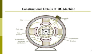
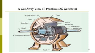
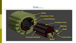
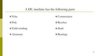
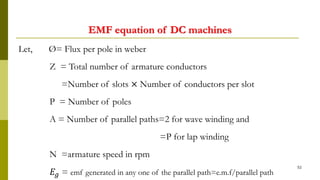
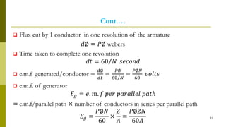
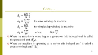
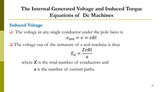
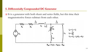
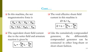


The document summarizes key aspects of DC machines, including: 1) DC machines convert mechanical energy to DC electric energy (generators) or convert DC electric energy to mechanical energy (motors). 2) They contain a commutator that converts internally generated AC to DC at the terminals. 3) Construction includes a yoke, poles, field windings, armature, commutator, and brushes. 4) Armature reaction distorts the magnetic field and weakens it as load increases. Commutation reverses current in coils as they pass the magnetic neutral axis.


