Downloaded 4,056 times
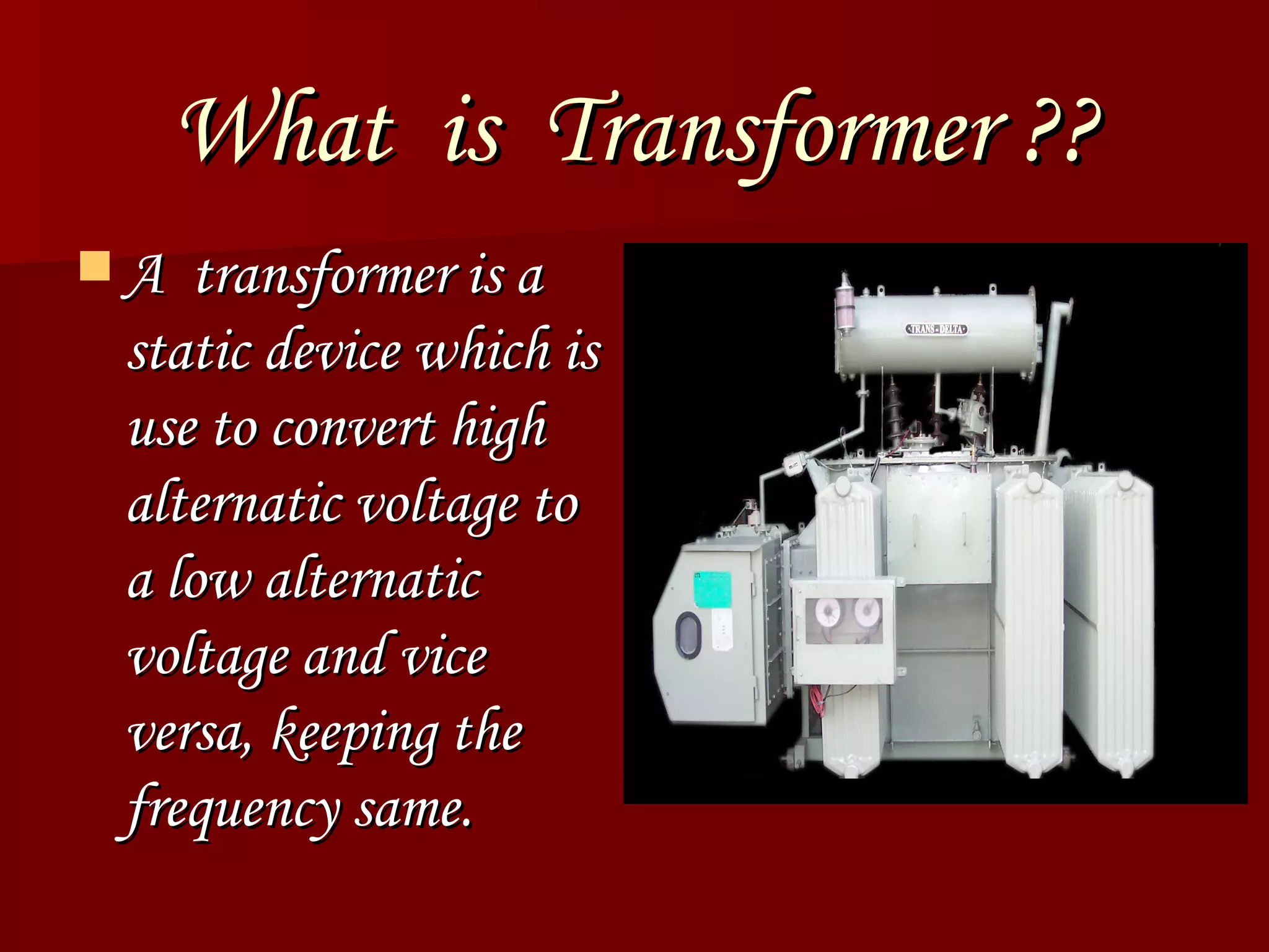
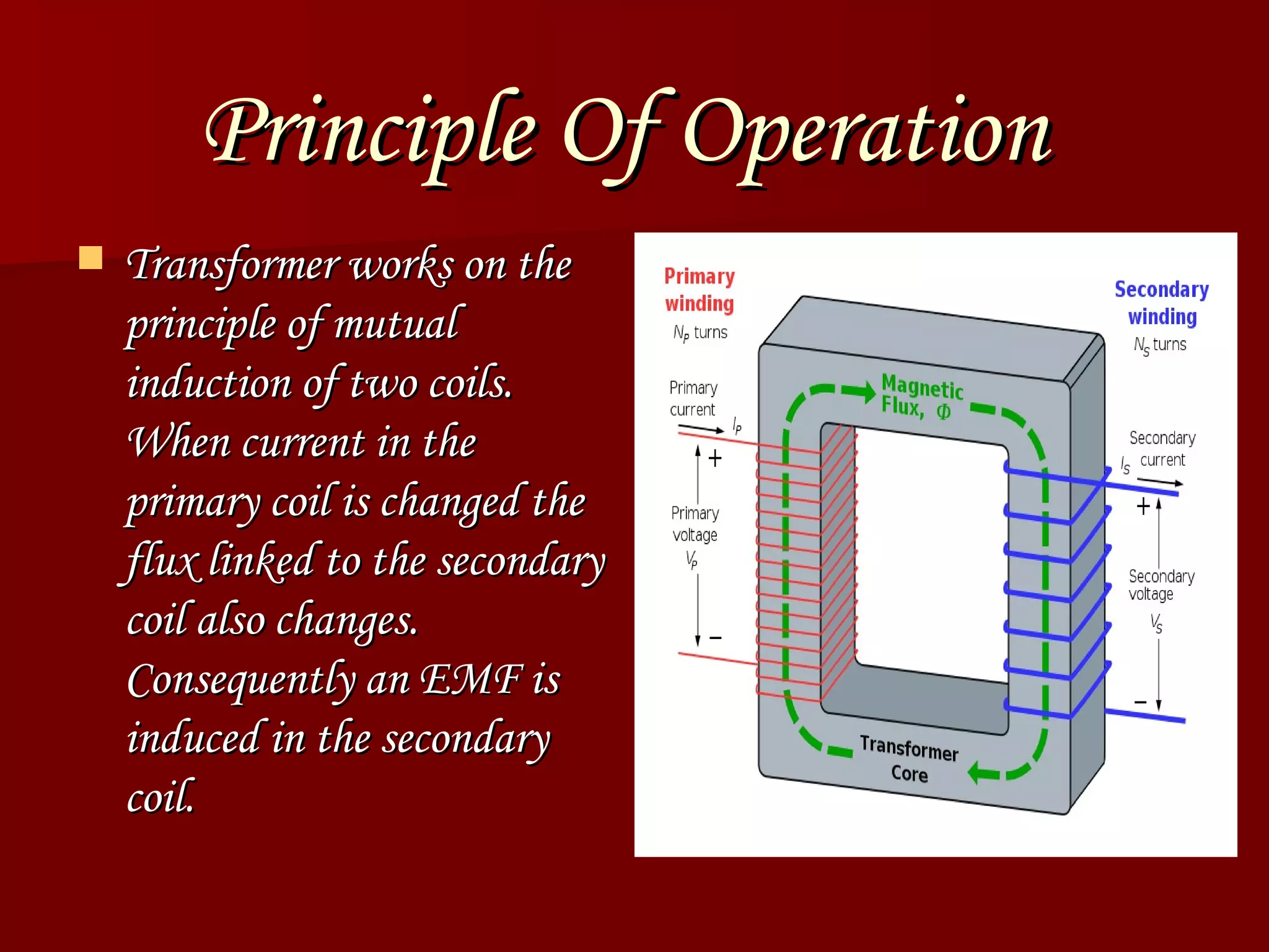
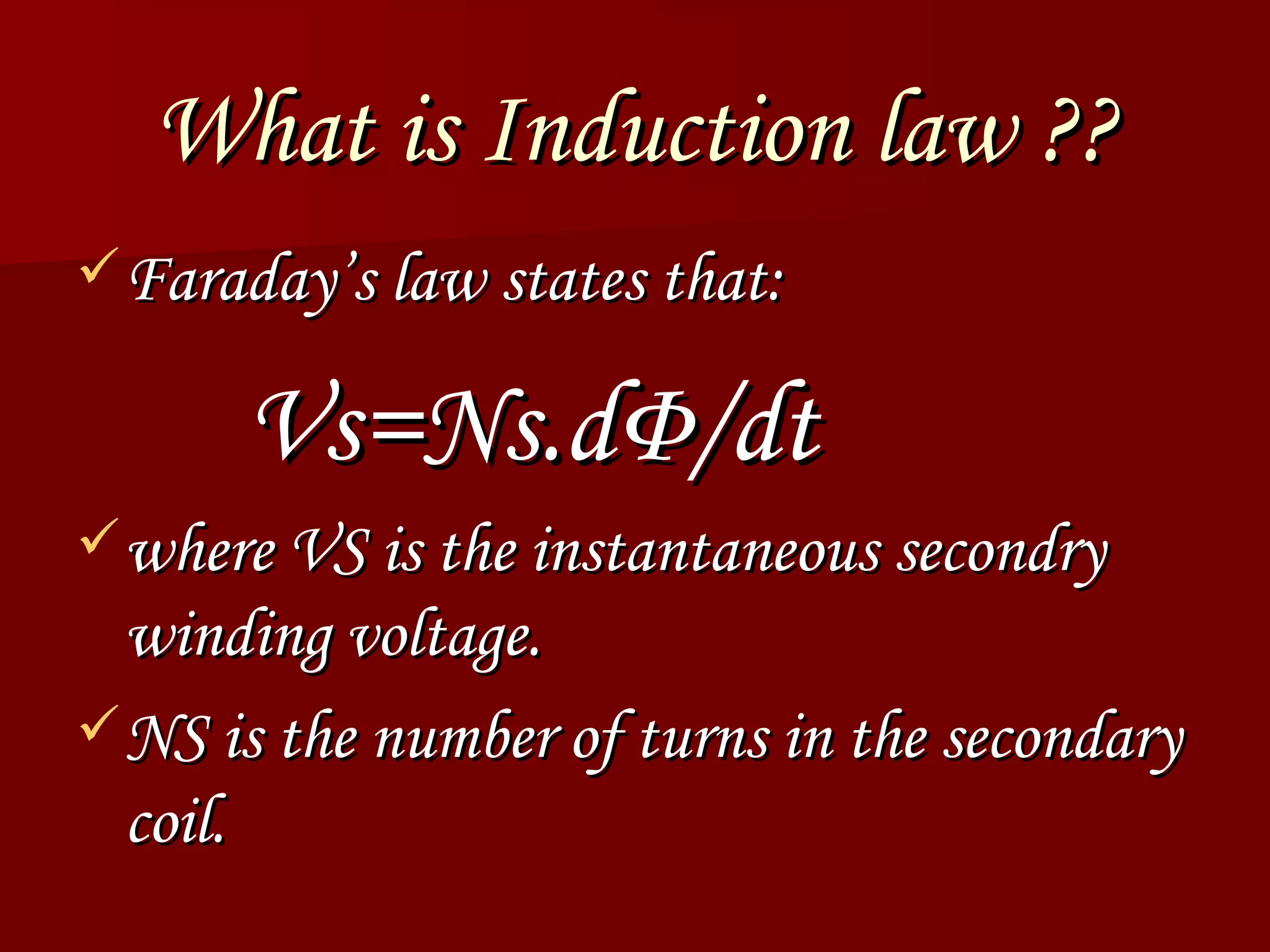
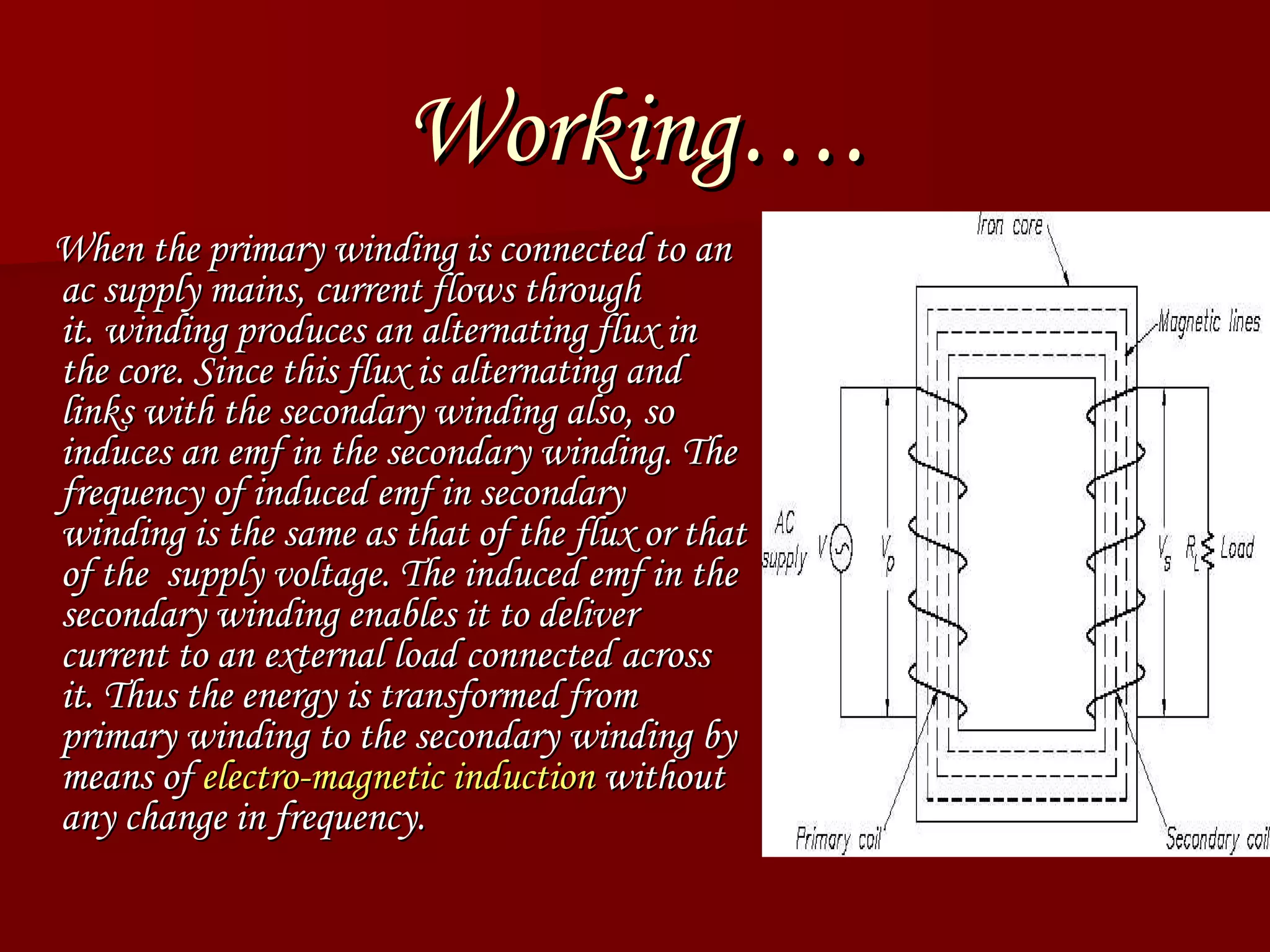
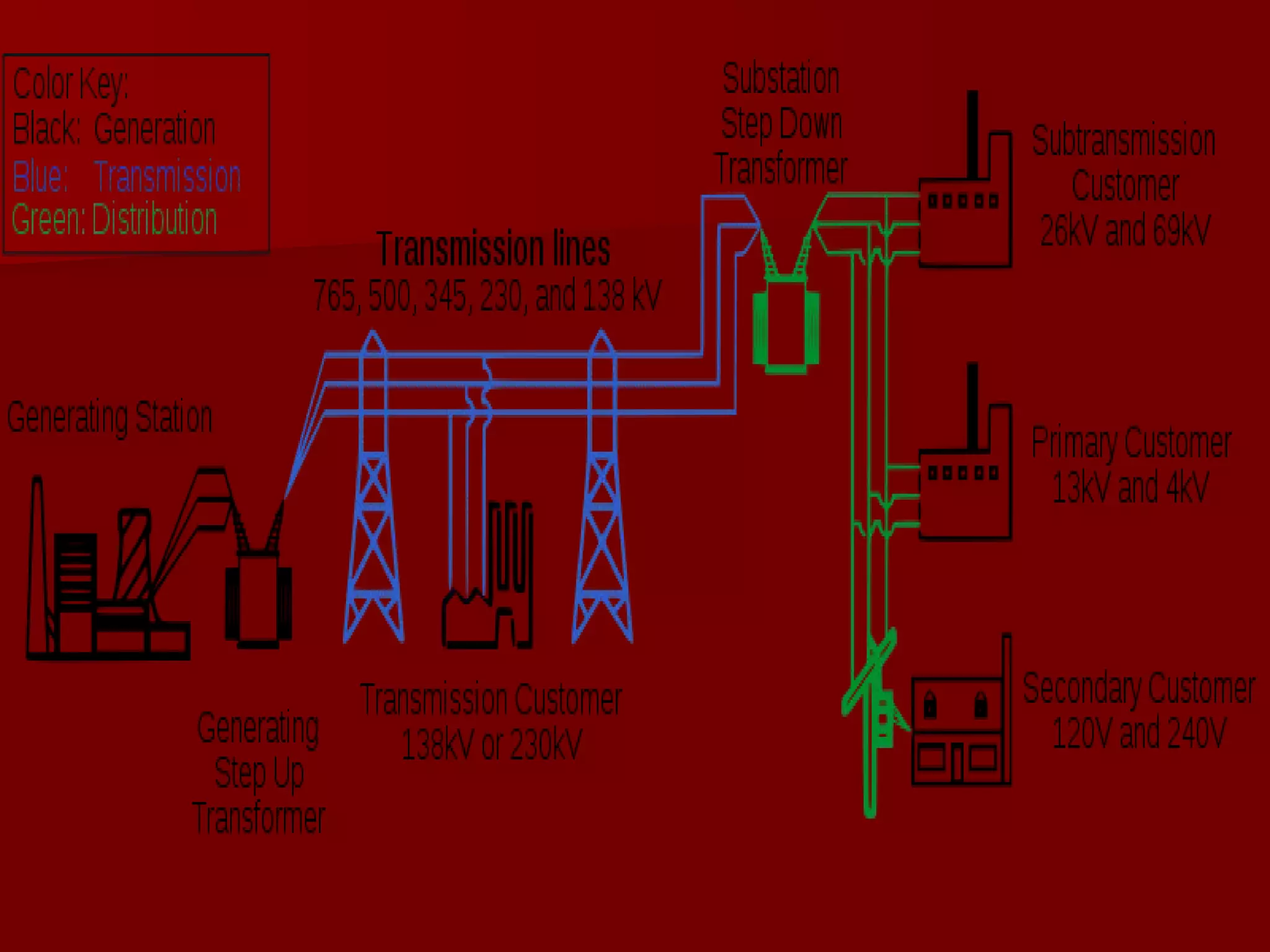


- A transformer is a static device that converts alternating current voltages to different voltages while keeping frequency the same through electromagnetic induction. - It works on the principle of mutual induction between two coils - an alternating current in the primary coil induces an alternating voltage in the secondary coil. - Transformers are used extensively in power transmission to increase voltage for long distance transmission lines and then reduce voltage for safe distribution, as well as in electronics to step down voltages for low-voltage circuits.
Introduction of Dheerendra Upadhyay and the educational context of the presentation.
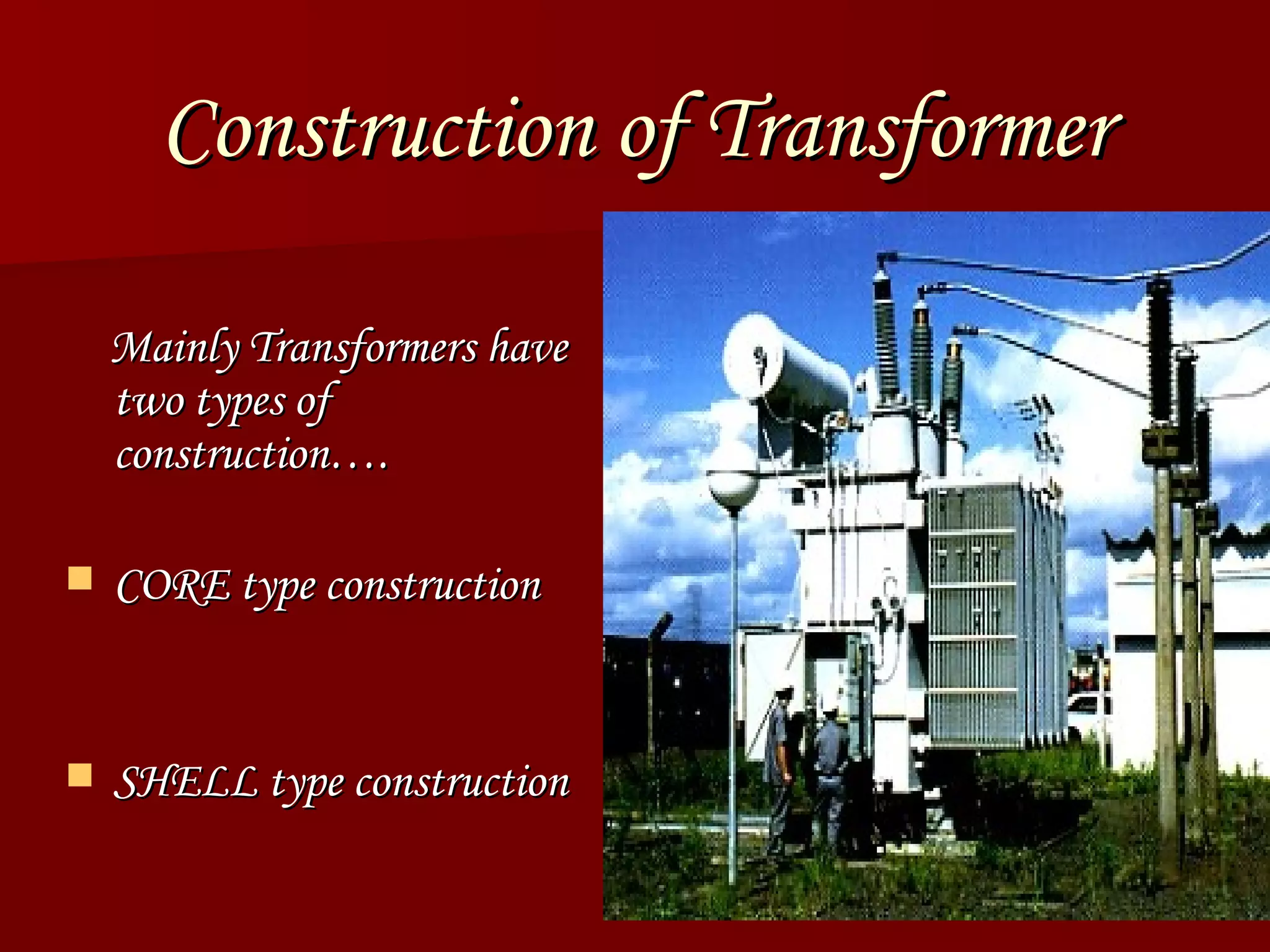
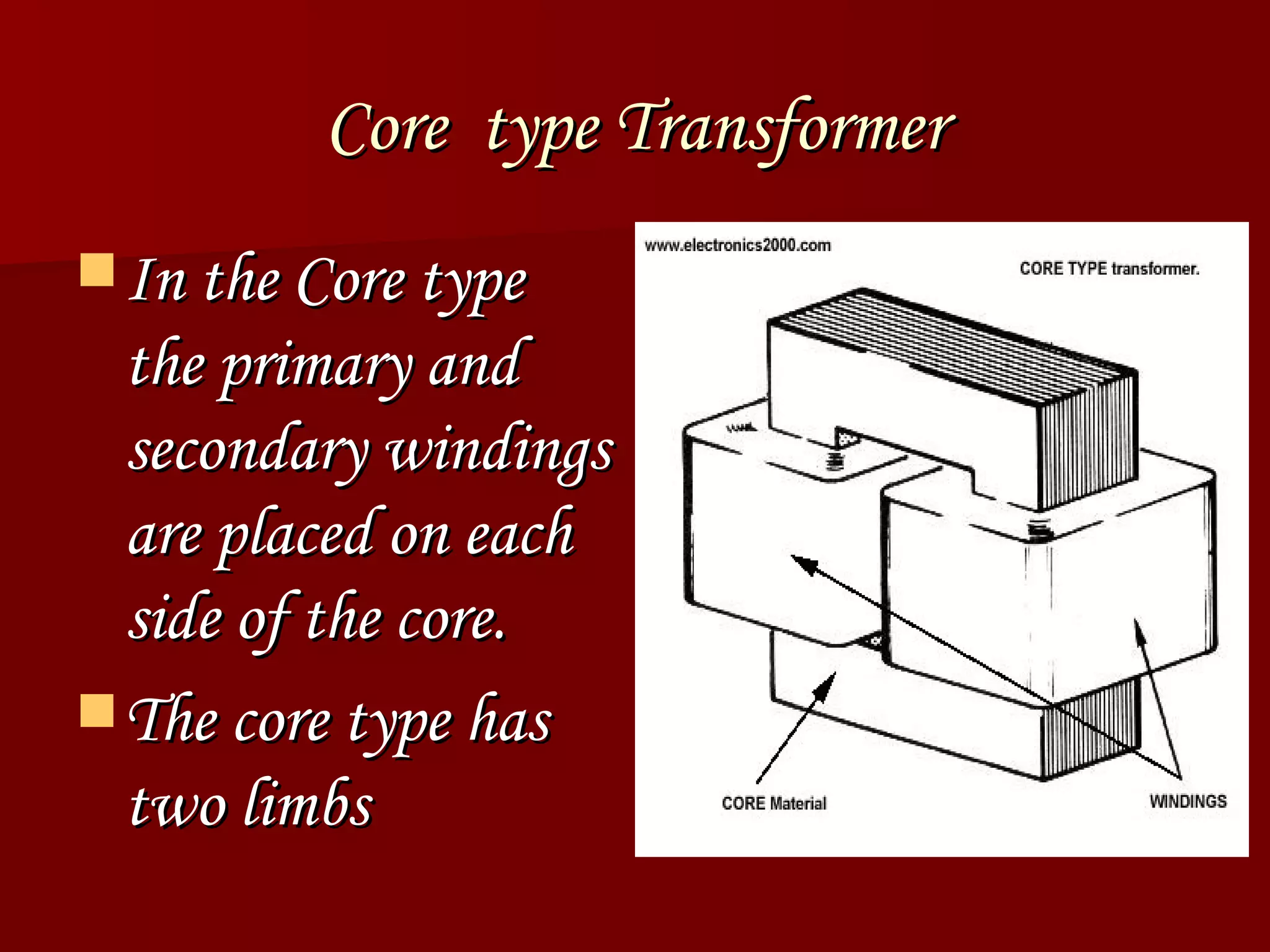
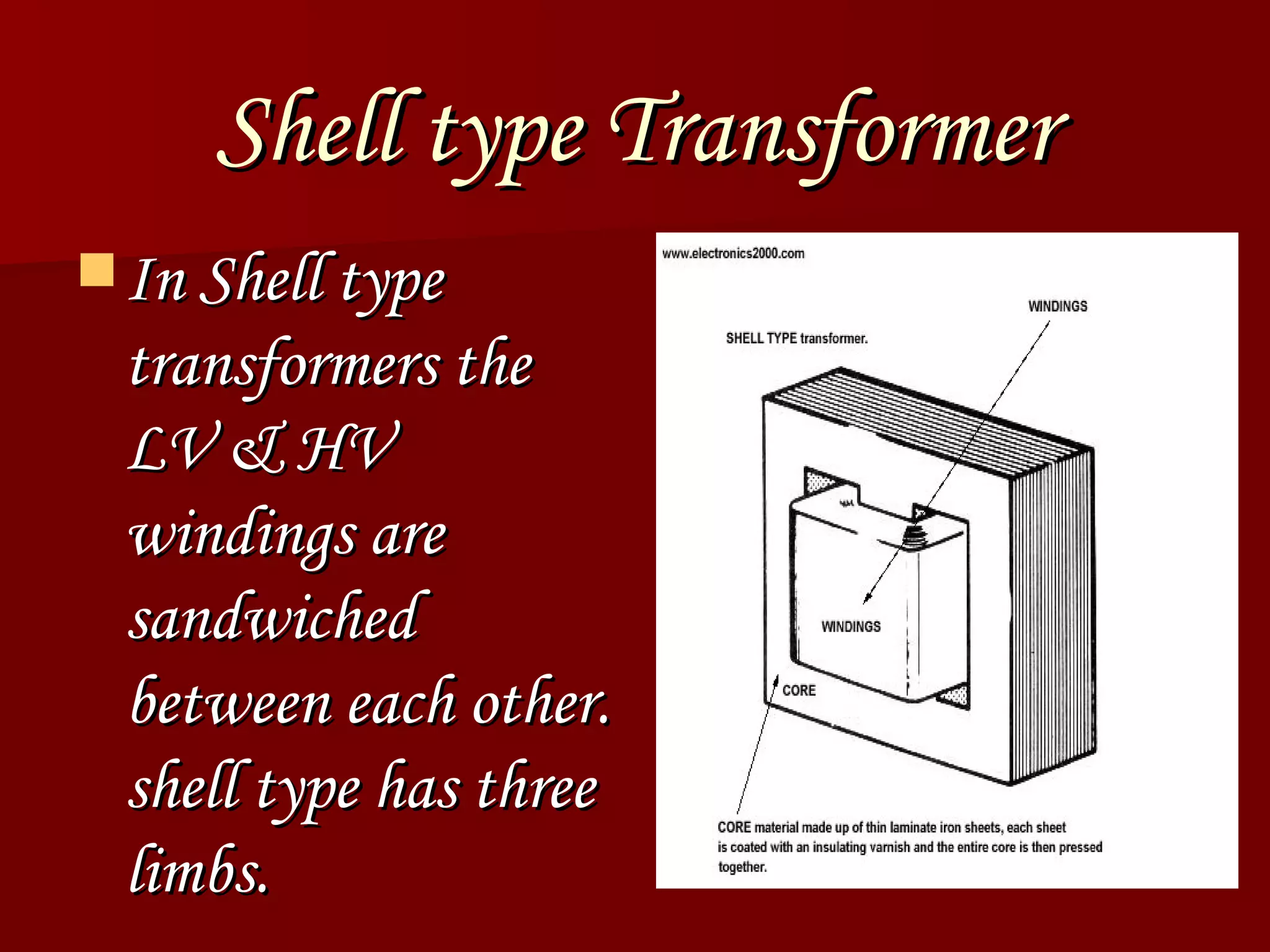
Transformers convert alternating voltages; operate on mutual induction; consist of core and shell constructions.Differences between core and shell type transformer constructions highlighting their designs.
Covers step-up and step-down transformers, along with other transformer variants used in applications.
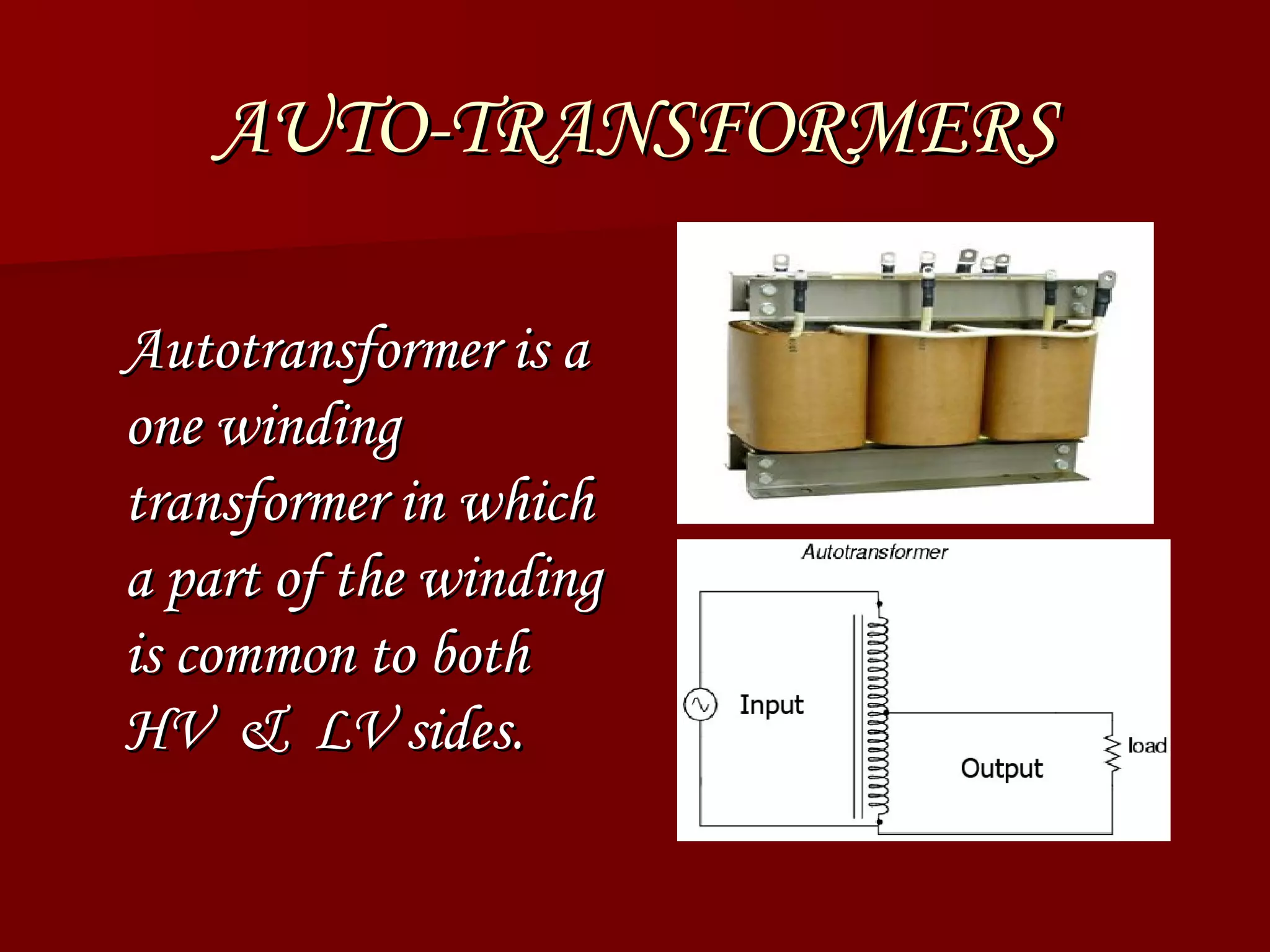
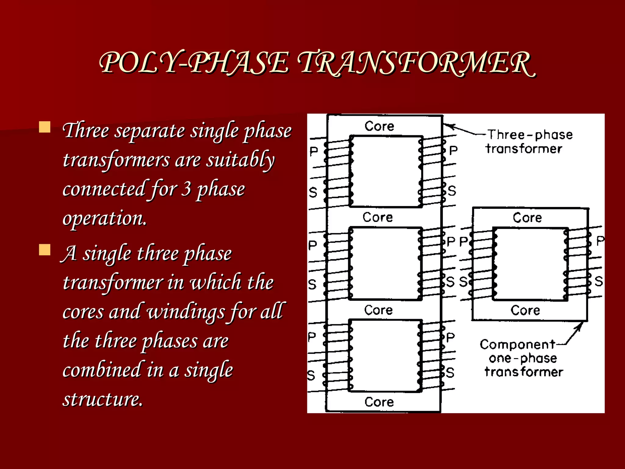
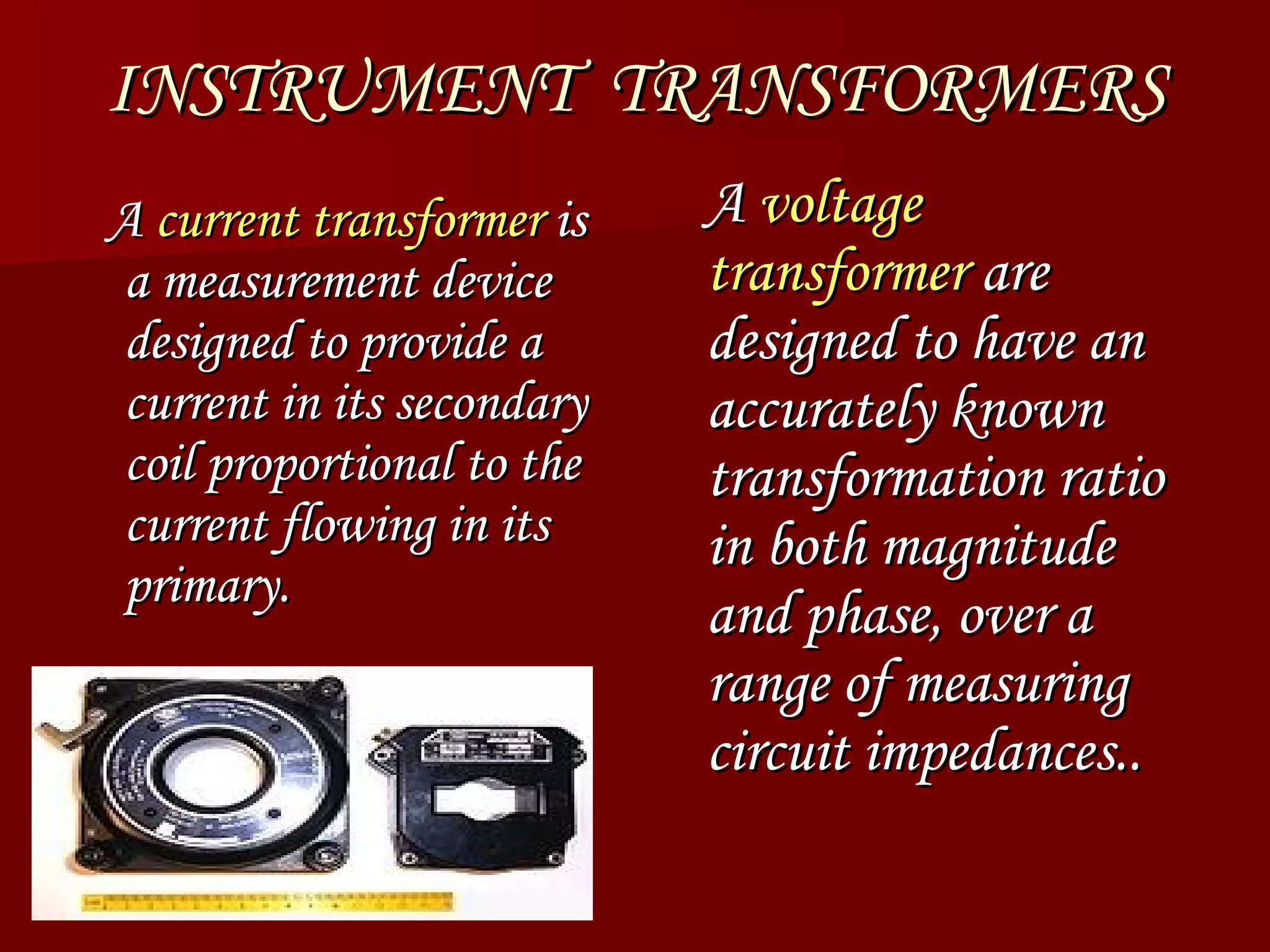
Details on auto-transformers, poly-phase transformers, and instrument transformers and their functions.
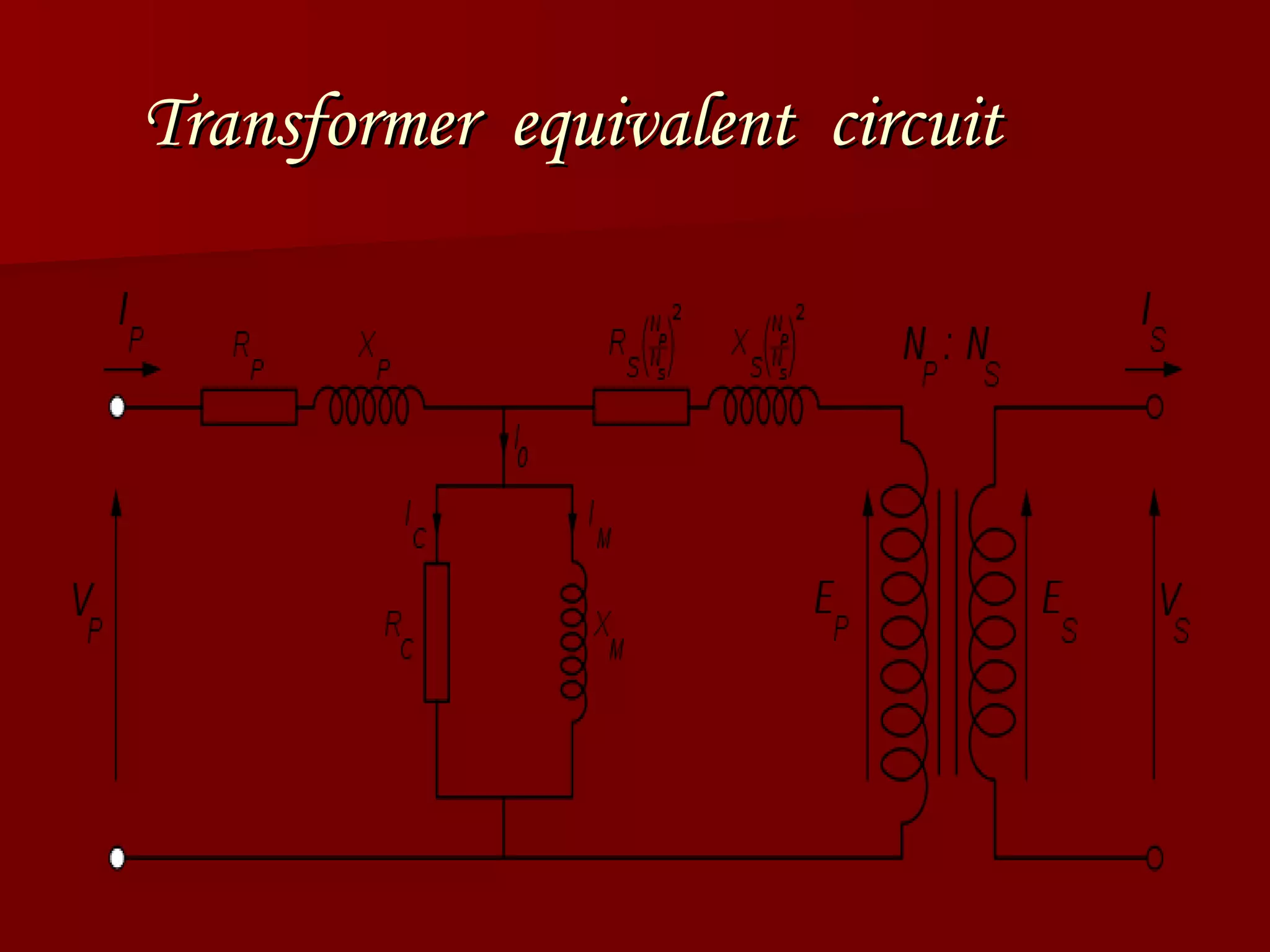
Illustration of transformer equivalent circuit essential for analysis.
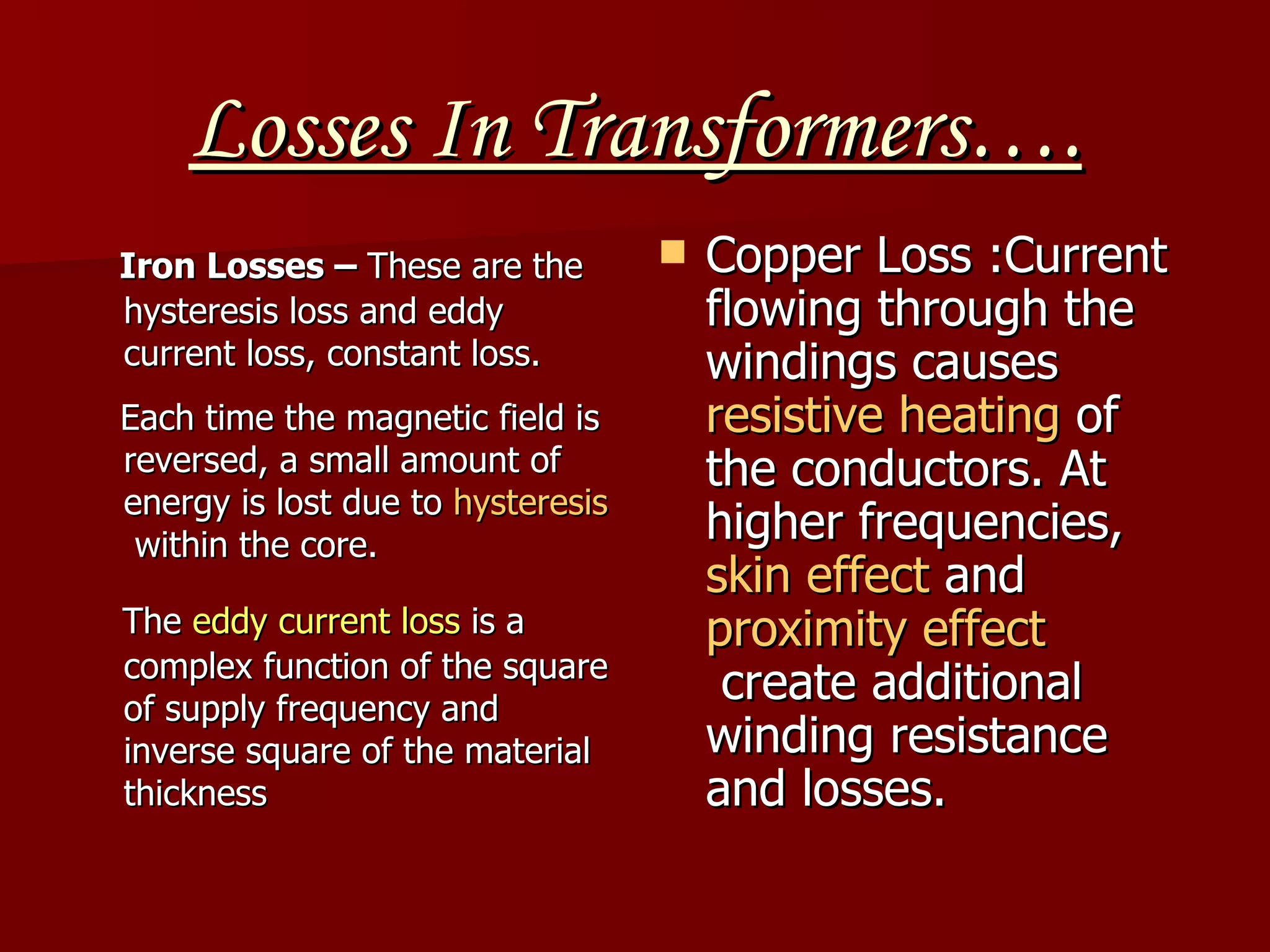
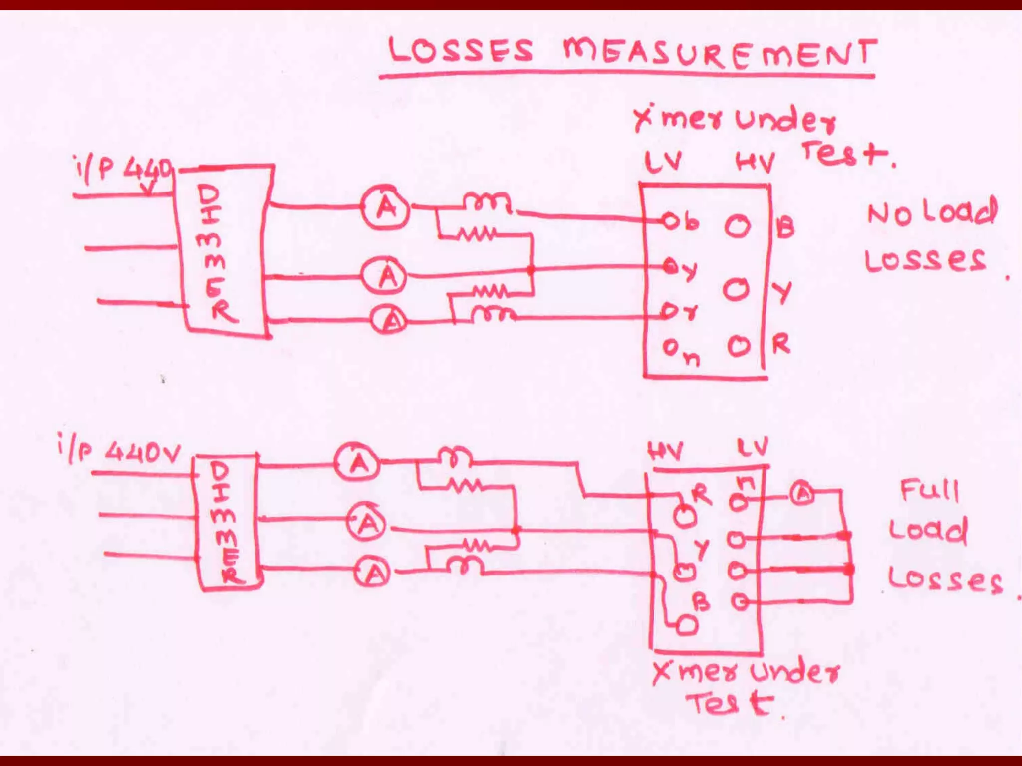
Studies iron losses, copper losses, and their implications on transformer efficiency.
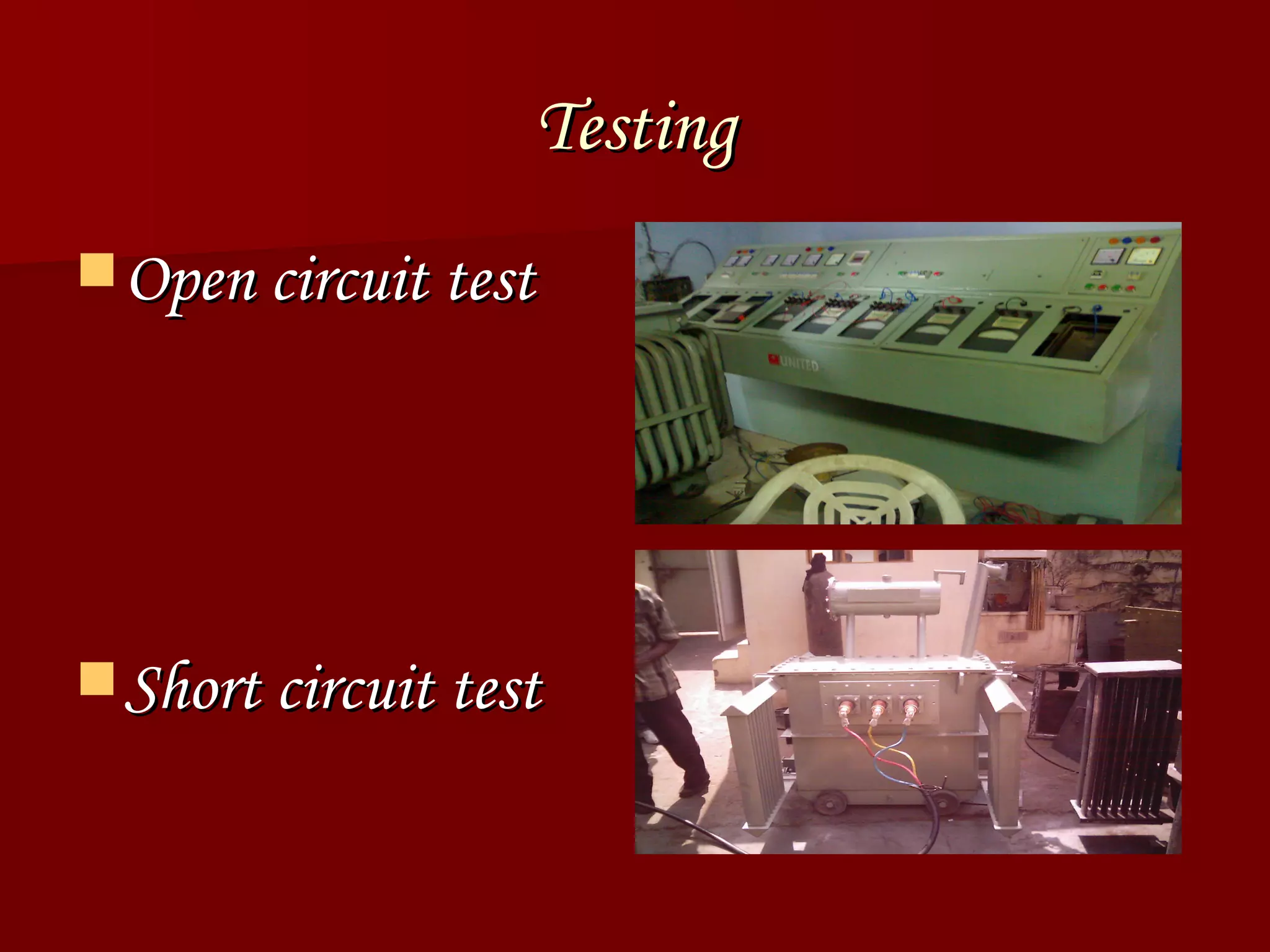
Description of open and short circuit tests conducted on transformers.
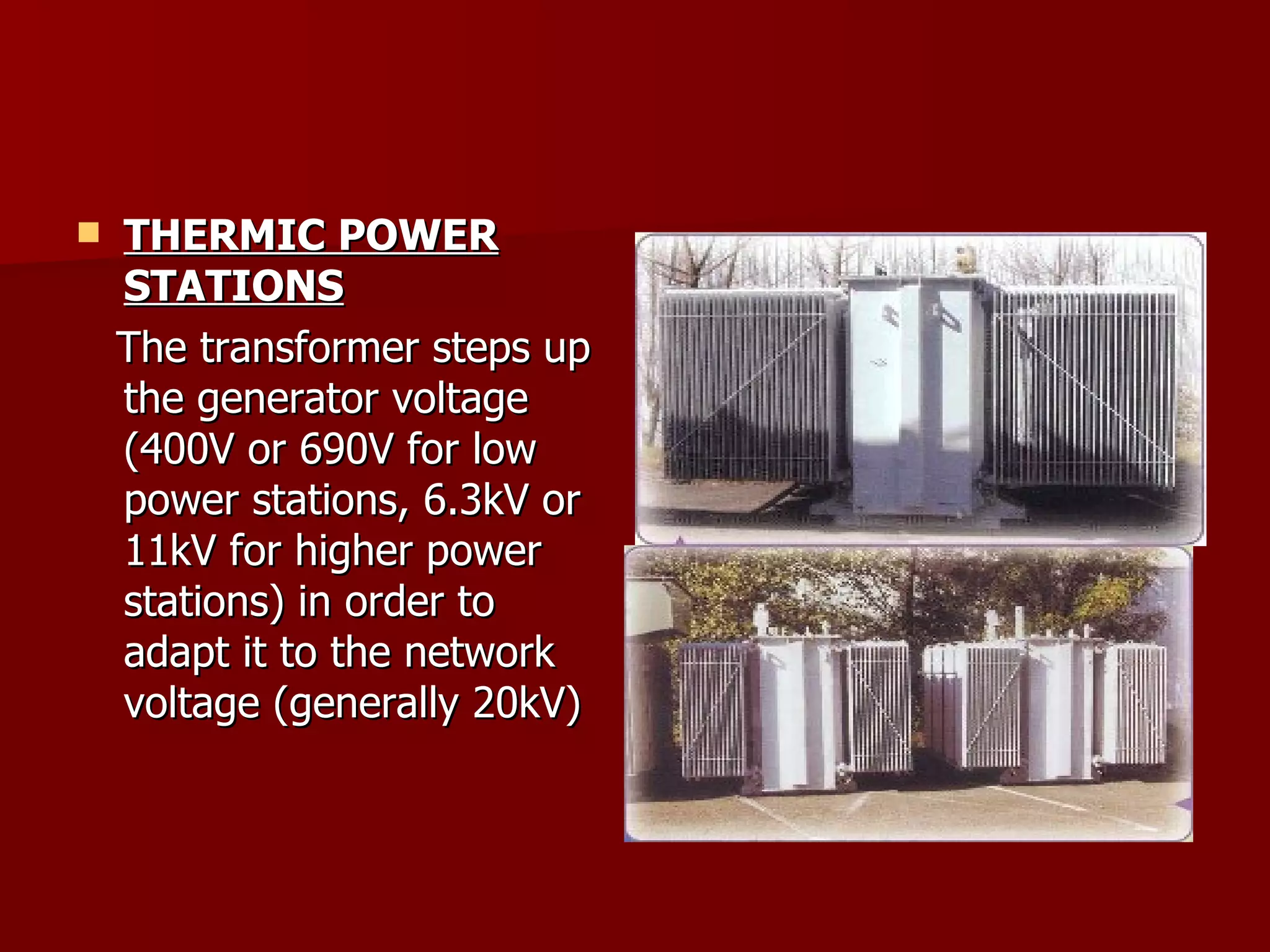
Discusses applications in power transmission, electronics, thermic power stations, and safety warnings.
Conclusion of the presentation and acknowledgment.


