Downloaded 187 times

![VOLTAGE REGULATION
• Regulation of transformer is defined as reduction in
magnitude of terminal voltage due to load wrt no-load
terminal voltage.
% Regulation = |V2 on no-load| - |V2 when loaded|
/ |V2 on no-load|
LAGGING POWER FACTOR
% Regulation = [I1 R01 cos Φ+ I1X01sin Φ ] X 100 /V1](https://image.slidesharecdn.com/btecheeiieeeu-4transformerelectricalwiringdipenpatel-150317003205-conversion-gate01/85/B-tech-ee-ii_-eee_-u-4_-transformer-electrical-wiring_dipen-patel-25-320.jpg)
![Copper Loss
This loss is due to the ohmic resistance of the transformer
windings.
Total Cu loss=I1
2
R1+I2
2
R2= I1
2
R01=I2
2
R02.
It is clear that Cu loss is proportional to (current)2
or kVA2
.
So, Cu loss at half-load is one-fourth [(1/2)2
=1/4] of that at full
load.
Cu loss at one-quarter-load is one-sixteen [(1/4)2
=1/16] of that at
full load.
Cu loss at five-fourths -load is twenty five by-sixteen
[(5/4)2
=25/16] of that at full load.
The value of copper loss is found from the short-circuit test.](https://image.slidesharecdn.com/btecheeiieeeu-4transformerelectricalwiringdipenpatel-150317003205-conversion-gate01/85/B-tech-ee-ii_-eee_-u-4_-transformer-electrical-wiring_dipen-patel-27-320.jpg)
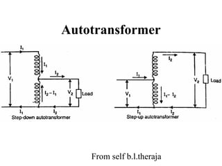


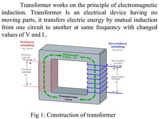
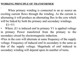
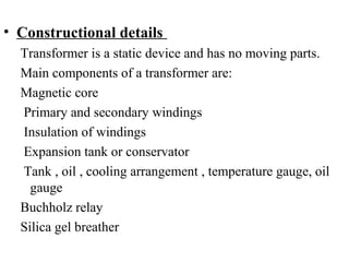
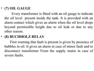
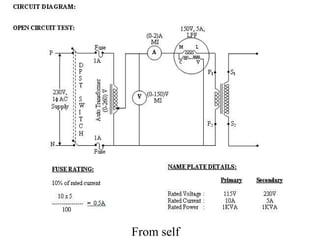
1. The document discusses the working principle, classification, construction, and testing of transformers. Transformers transfer electric energy from one circuit to another via electromagnetic induction without moving parts. 2. Transformers are classified based on factors like their duty, construction, voltage output, application, cooling type, and input supply. Common types include power transformers, current transformers, potential transformers, step-up transformers, and step-down transformers. 3. The main components of a transformer are the magnetic core, primary and secondary windings, insulation, oil for cooling and insulation, and protective devices like the Buchholz relay. Open-circuit and short-circuit tests are used to determine the equivalent circuit parameters of transformers.