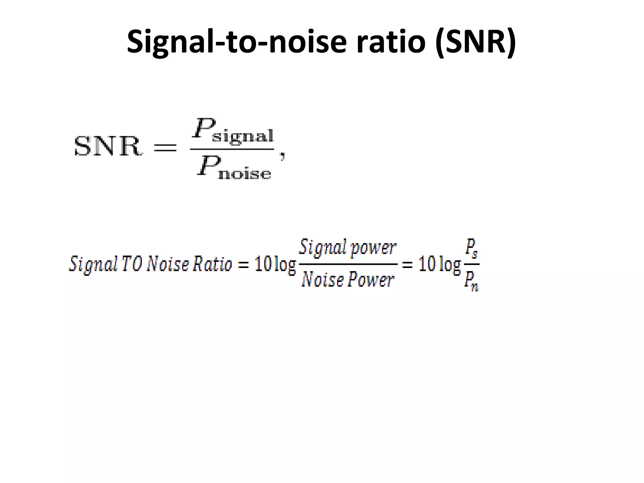
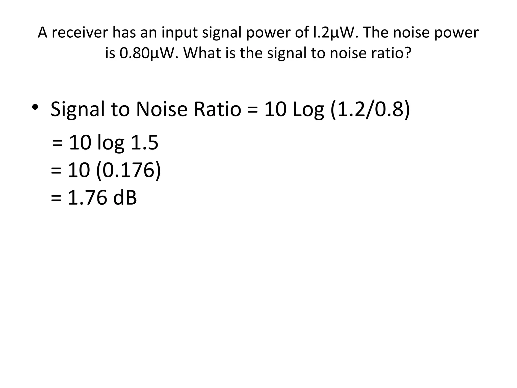
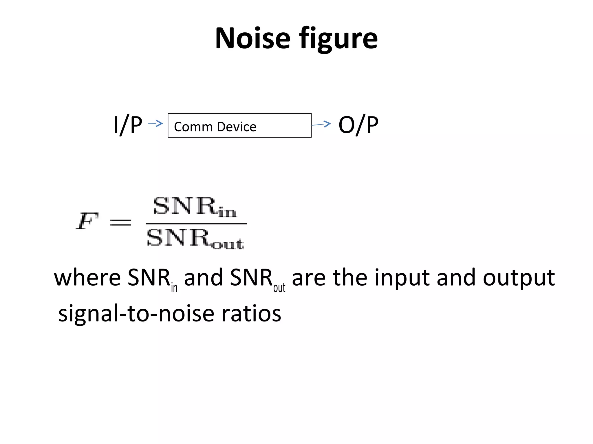
Transmission Impairments
Reference: Digital Telephony,
John C. Bellamy
Attenuation:
• Attenuation affects the propagation of waves and
signals in electrical circuits, in optical fibers, as well as
in air (radio waves).
• Attenuation is reduction of signal strength during
transmission. Attenuation is the opposite of
amplification, and is normal when a signal is sent from
one point to another. If the signal attenuates too
much, it becomes unintelligible, which is why most
networks require repeaters at regular intervals.
Attenuation is measured in decibels.
• Naturally, attenuation happens exponentially with the
travelled distance.
Distortion
• Distortion is known as the alternation of the original
signal. This may happen due to the properties of the
medium. There are many types of distortion such as
amplitude distortion, harmonic distortion, and phase
distortion. For electromagnetic waves polarization
distortions also occurs. When the distortion occurs,
shape of the waveform is changed.
• For example, amplitude distortion happens if all the
parts of the signals are not equally amplified. This
happens in wireless transmissions because the
medium get changed by the time. The receivers should
be able to identify these distortions.
Distortion
Distortion
Types:
• Amplitude distortion
• Delay / Phase Distortion
• Frequency related distortion
Difference between attenuation and distortion
1. Although scaled down in amplitude, shape of
waveform does not change in attenuation
unlike in distortion.
2. Removal of the effects of attenuation is easier
than a removing the effects distortion.
3. If the attenuation happens in different
amounts for the different parts of the signal, it
is a distortion.
Noise
Reference: Electronic
Communication System
Sanjeev Gupta
Noise
The random and unpredicted electrical signal
(coming from both internal or external portion
of the system) which interfere the reception
of actual required signal is called- noise.
Noise can be characterized by statistical
parameter such as averaged/ squared noise,
current/ voltage etc.
Signal-to-noise ratio (SNR)
A receiver has an input signal power of l.2µW. The noise power
is 0.80µW. What is the signal to noise ratio?
• Signal to Noise Ratio = 10 Log (1.2/0.8)
= 10 log 1.5
= 10 (0.176)
= 1.76 dB
Noise figure
I/P O/P
where SNRin and SNRout are the input and output
signal-to-noise ratios
Comm Device
Noise-equivalent temperature
It is a reference measurement between a
minimum noise level due to thermal noise and
total (ext.+ int.) noise.
Teq= To (F-1)
Classification of Noise
• External noises, i.e. noise whose sources are
external
– Atmospheric noises
– Extraterrestrial noises
– Man-made noises or industrial noises.
• Internal noise in communication, i.e. noises
which get, generated within the receiver or
communication system.
– Thermal noise or white noise or Johnson noise
– Shot noise.
– Transit time noise
- Miscellaneous internal noise

Transmission impairments

  • 1.
  • 2.
    Attenuation: • Attenuation affectsthe propagation of waves and signals in electrical circuits, in optical fibers, as well as in air (radio waves). • Attenuation is reduction of signal strength during transmission. Attenuation is the opposite of amplification, and is normal when a signal is sent from one point to another. If the signal attenuates too much, it becomes unintelligible, which is why most networks require repeaters at regular intervals. Attenuation is measured in decibels. • Naturally, attenuation happens exponentially with the travelled distance.
  • 3.
    Distortion • Distortion isknown as the alternation of the original signal. This may happen due to the properties of the medium. There are many types of distortion such as amplitude distortion, harmonic distortion, and phase distortion. For electromagnetic waves polarization distortions also occurs. When the distortion occurs, shape of the waveform is changed. • For example, amplitude distortion happens if all the parts of the signals are not equally amplified. This happens in wireless transmissions because the medium get changed by the time. The receivers should be able to identify these distortions.
  • 4.
  • 5.
    Distortion Types: • Amplitude distortion •Delay / Phase Distortion • Frequency related distortion
  • 6.
    Difference between attenuationand distortion 1. Although scaled down in amplitude, shape of waveform does not change in attenuation unlike in distortion. 2. Removal of the effects of attenuation is easier than a removing the effects distortion. 3. If the attenuation happens in different amounts for the different parts of the signal, it is a distortion.
  • 7.
  • 8.
    Noise The random andunpredicted electrical signal (coming from both internal or external portion of the system) which interfere the reception of actual required signal is called- noise. Noise can be characterized by statistical parameter such as averaged/ squared noise, current/ voltage etc.
  • 9.
  • 10.
    A receiver hasan input signal power of l.2µW. The noise power is 0.80µW. What is the signal to noise ratio? • Signal to Noise Ratio = 10 Log (1.2/0.8) = 10 log 1.5 = 10 (0.176) = 1.76 dB
  • 11.
    Noise figure I/P O/P whereSNRin and SNRout are the input and output signal-to-noise ratios Comm Device
  • 12.
    Noise-equivalent temperature It isa reference measurement between a minimum noise level due to thermal noise and total (ext.+ int.) noise. Teq= To (F-1)
  • 13.
    Classification of Noise •External noises, i.e. noise whose sources are external – Atmospheric noises – Extraterrestrial noises – Man-made noises or industrial noises.
  • 14.
    • Internal noisein communication, i.e. noises which get, generated within the receiver or communication system. – Thermal noise or white noise or Johnson noise – Shot noise. – Transit time noise - Miscellaneous internal noise