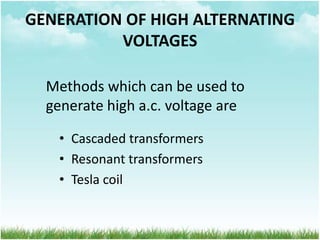
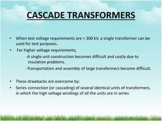
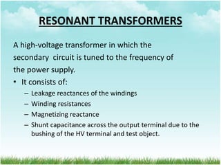
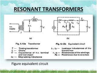
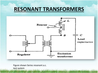
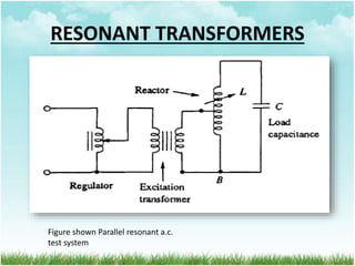
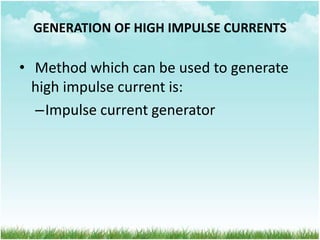
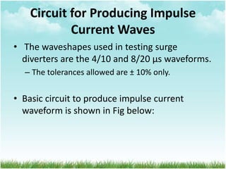
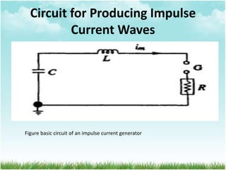
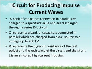
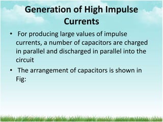
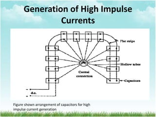
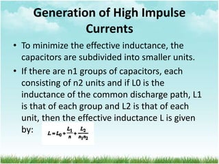
This document discusses different methods for generating high voltages and currents, including cascade transformers, resonant transformers, and Tesla coils for AC voltages, and single-stage and Marx generators for impulse voltages. It also covers impulse current generation using a bank of parallel capacitors discharged through an R-L circuit. Cascade transformers consist of multiple transformer stages connected in series to achieve high voltages. Resonant transformers use tuning of the secondary circuit. Tesla coils produce high frequency AC through magnetic coupling of primary and secondary air-core coils.
Generation of High D.C. Voltage (HVDC generation)RP6997
Generation of high dc voltage using different methods like half wave and full wave rectifier, voltage doubler circuits, voltage multiplier circuits, cockcroft-walton circuits and van de graaff generators.
Generation of High D.C. Voltage (HVDC generation)RP6997
Generation of high dc voltage using different methods like half wave and full wave rectifier, voltage doubler circuits, voltage multiplier circuits, cockcroft-walton circuits and van de graaff generators.
Design factors; Limitations; Modern trends; Electrical
Engineering Materials; Space factor; Choice of Specific
Electric and Magnetic loadings; Thermal Considerations;
Heat flow; Temperature rise; Insulating Materials; Properties;
Rating of Machines; Various Standard Specifications ;
Unit I: Introduction to Protection System:
Introduction to protection system and its elements, functions of protective relaying, protective zones, primary and backup protection, desirable qualities of protective relaying, basic terminology.
Relays:
Electromagnetic, attracted and induction type relays, thermal relay, gas actuated relay, design considerations of electromagnetic relay.
Unit-II: Relay Application and Characteristics:
Amplitude and phase comparators, over current relays, directional relays, distance relays, differential relay.
Static Relays: Comparison with electromagnetic relay, classification and their description, over current relays, directional relay, distance relays, differential relay.
Unit-III Protection of Transmission Line:
Over current protection, distance protection, pilot wire protection, carrier current protection, protection of bus, auto re-closing,
Unit-IV: Circuit Breaking:
Properties of arc, arc extinction theories, re-striking voltage transient, current chopping, resistance switching, capacitive current interruption, short line interruption, circuit breaker ratings.
Testing Of Circuit Breaker: Classification, testing station and equipments, testing procedure, direct and indirect testing.
Unit-V Apparatus Protection:
Protection of Transformer, generator and motor.
Circuit Breaker: Operating modes, selection of circuit breakers, constructional features and operation of Bulk Oil, Minimum Oil, Air Blast, SF6, Vacuum and d. c. circuit breakers.
We had made a working model on static VAR compensator which is made by power electronic switch and mechanically switched. We had chosen mechanically switched capacitor method to improved receiving end voltage as well as power factor.
Module 2 ee369 KTU syllabus-high voltage ac generation,resonant circuitsAsha Anu Kurian
Generation of high AC voltages-Testing transformer – single unit testing transformer, cascaded transformer – equivalent circuit of cascaded transformer – generation of high frequency AC voltages- series resonance circuit – resonant transformer – voltage regulation.
Introduction, equipment required for HVDC systems, Comparison of AC and DC Transmission, Limitations of HVDC transmission lines, reliability of HVDC systems, comparison of HVDC link with EHVAC link, HVDC system configuration and components, fundamental equations in HVDC system, HVDC links, converter theory and performance equation, valve characteristic, converter circuits, converter transformer testing, multi bridge converters, abnormal operation of HVDC system, control of HVDC system, harmonics and filters. Influence of AC system strength on AC/DC system interaction, response to AC and DC system faults, Concept of reactive power compensation- reactive Power balance in HVDC substations-Effect of angle of advance and extinction angle on reactive power requirement of converters.
Introduction, Operation of 12-pulse converter as receiving and sending terminals of HVDC system, Equipment required for HVDC System and their significance, Comparison of AC and DC transmission, Control of HVDC transmission
Chaper 4 Unit 1 Basics of HVDC Transmission.pptonlystu007
Introduction in High voltage dc you are
HVDC stands for High Voltage Direct Current. It's a technology used for transmitting electricity over long distances with lower energy losses compared to traditional AC (Alternating Current) transmission systems. HVDC systems are often used for interconnecting power grids, transmitting power from remote renewable energy sources, and improving grid stability. They involve converting AC to DC at the sending end, transmitting the power via cables or overhead lines, and then converting it back to AC at the receiving end. HVDC stands for High Voltage Direct Current. It's a technology used for transmitting electricity over long distances with lower energy losses compared to traditional AC (Alternating Current) transmission systems. HVDC systems are often used for interconnecting power grids, transmitting power from remote renewable energy sources, and improving grid stability. They involve converting AC to DC at the sending end, transmitting the power via cables or overhead lines, and then converting it back to AC at the receiving end.
Hybrid optimization of pumped hydro system and solar- Engr. Abdul-Azeez.pdffxintegritypublishin
Advancements in technology unveil a myriad of electrical and electronic breakthroughs geared towards efficiently harnessing limited resources to meet human energy demands. The optimization of hybrid solar PV panels and pumped hydro energy supply systems plays a pivotal role in utilizing natural resources effectively. This initiative not only benefits humanity but also fosters environmental sustainability. The study investigated the design optimization of these hybrid systems, focusing on understanding solar radiation patterns, identifying geographical influences on solar radiation, formulating a mathematical model for system optimization, and determining the optimal configuration of PV panels and pumped hydro storage. Through a comparative analysis approach and eight weeks of data collection, the study addressed key research questions related to solar radiation patterns and optimal system design. The findings highlighted regions with heightened solar radiation levels, showcasing substantial potential for power generation and emphasizing the system's efficiency. Optimizing system design significantly boosted power generation, promoted renewable energy utilization, and enhanced energy storage capacity. The study underscored the benefits of optimizing hybrid solar PV panels and pumped hydro energy supply systems for sustainable energy usage. Optimizing the design of solar PV panels and pumped hydro energy supply systems as examined across diverse climatic conditions in a developing country, not only enhances power generation but also improves the integration of renewable energy sources and boosts energy storage capacities, particularly beneficial for less economically prosperous regions. Additionally, the study provides valuable insights for advancing energy research in economically viable areas. Recommendations included conducting site-specific assessments, utilizing advanced modeling tools, implementing regular maintenance protocols, and enhancing communication among system components.
Saudi Arabia stands as a titan in the global energy landscape, renowned for its abundant oil and gas resources. It's the largest exporter of petroleum and holds some of the world's most significant reserves. Let's delve into the top 10 oil and gas projects shaping Saudi Arabia's energy future in 2024.
Student information management system project report ii.pdfKamal Acharya
Our project explains about the student management. This project mainly explains the various actions related to student details. This project shows some ease in adding, editing and deleting the student details. It also provides a less time consuming process for viewing, adding, editing and deleting the marks of the students.
Online aptitude test management system project report.pdfKamal Acharya
The purpose of on-line aptitude test system is to take online test in an efficient manner and no time wasting for checking the paper. The main objective of on-line aptitude test system is to efficiently evaluate the candidate thoroughly through a fully automated system that not only saves lot of time but also gives fast results. For students they give papers according to their convenience and time and there is no need of using extra thing like paper, pen etc. This can be used in educational institutions as well as in corporate world. Can be used anywhere any time as it is a web based application (user Location doesn’t matter). No restriction that examiner has to be present when the candidate takes the test.
Every time when lecturers/professors need to conduct examinations they have to sit down think about the questions and then create a whole new set of questions for each and every exam. In some cases the professor may want to give an open book online exam that is the student can take the exam any time anywhere, but the student might have to answer the questions in a limited time period. The professor may want to change the sequence of questions for every student. The problem that a student has is whenever a date for the exam is declared the student has to take it and there is no way he can take it at some other time. This project will create an interface for the examiner to create and store questions in a repository. It will also create an interface for the student to take examinations at his convenience and the questions and/or exams may be timed. Thereby creating an application which can be used by examiners and examinee’s simultaneously.
Examination System is very useful for Teachers/Professors. As in the teaching profession, you are responsible for writing question papers. In the conventional method, you write the question paper on paper, keep question papers separate from answers and all this information you have to keep in a locker to avoid unauthorized access. Using the Examination System you can create a question paper and everything will be written to a single exam file in encrypted format. You can set the General and Administrator password to avoid unauthorized access to your question paper. Every time you start the examination, the program shuffles all the questions and selects them randomly from the database, which reduces the chances of memorizing the questions.
Welcome to WIPAC Monthly the magazine brought to you by the LinkedIn Group Water Industry Process Automation & Control.
In this month's edition, along with this month's industry news to celebrate the 13 years since the group was created we have articles including
A case study of the used of Advanced Process Control at the Wastewater Treatment works at Lleida in Spain
A look back on an article on smart wastewater networks in order to see how the industry has measured up in the interim around the adoption of Digital Transformation in the Water Industry.
KuberTENes Birthday Bash Guadalajara - K8sGPT first impressionsVictor Morales
K8sGPT is a tool that analyzes and diagnoses Kubernetes clusters. This presentation was used to share the requirements and dependencies to deploy K8sGPT in a local environment.
Sachpazis:Terzaghi Bearing Capacity Estimation in simple terms with Calculati...Dr.Costas Sachpazis
Terzaghi's soil bearing capacity theory, developed by Karl Terzaghi, is a fundamental principle in geotechnical engineering used to determine the bearing capacity of shallow foundations. This theory provides a method to calculate the ultimate bearing capacity of soil, which is the maximum load per unit area that the soil can support without undergoing shear failure. The Calculation HTML Code included.
Cosmetic shop management system project report.pdfKamal Acharya
Buying new cosmetic products is difficult. It can even be scary for those who have sensitive skin and are prone to skin trouble. The information needed to alleviate this problem is on the back of each product, but it's thought to interpret those ingredient lists unless you have a background in chemistry.
Instead of buying and hoping for the best, we can use data science to help us predict which products may be good fits for us. It includes various function programs to do the above mentioned tasks.
Data file handling has been effectively used in the program.
The automated cosmetic shop management system should deal with the automation of general workflow and administration process of the shop. The main processes of the system focus on customer's request where the system is able to search the most appropriate products and deliver it to the customers. It should help the employees to quickly identify the list of cosmetic product that have reached the minimum quantity and also keep a track of expired date for each cosmetic product. It should help the employees to find the rack number in which the product is placed.It is also Faster and more efficient way.
Literature Review Basics and Understanding Reference Management.pptxDr Ramhari Poudyal
Three-day training on academic research focuses on analytical tools at United Technical College, supported by the University Grant Commission, Nepal. 24-26 May 2024
NO1 Uk best vashikaran specialist in delhi vashikaran baba near me online vas...Amil Baba Dawood bangali
Contact with Dawood Bhai Just call on +92322-6382012 and we'll help you. We'll solve all your problems within 12 to 24 hours and with 101% guarantee and with astrology systematic. If you want to take any personal or professional advice then also you can call us on +92322-6382012 , ONLINE LOVE PROBLEM & Other all types of Daily Life Problem's.Then CALL or WHATSAPP us on +92322-6382012 and Get all these problems solutions here by Amil Baba DAWOOD BANGALI
#vashikaranspecialist #astrologer #palmistry #amliyaat #taweez #manpasandshadi #horoscope #spiritual #lovelife #lovespell #marriagespell#aamilbabainpakistan #amilbabainkarachi #powerfullblackmagicspell #kalajadumantarspecialist #realamilbaba #AmilbabainPakistan #astrologerincanada #astrologerindubai #lovespellsmaster #kalajaduspecialist #lovespellsthatwork #aamilbabainlahore#blackmagicformarriage #aamilbaba #kalajadu #kalailam #taweez #wazifaexpert #jadumantar #vashikaranspecialist #astrologer #palmistry #amliyaat #taweez #manpasandshadi #horoscope #spiritual #lovelife #lovespell #marriagespell#aamilbabainpakistan #amilbabainkarachi #powerfullblackmagicspell #kalajadumantarspecialist #realamilbaba #AmilbabainPakistan #astrologerincanada #astrologerindubai #lovespellsmaster #kalajaduspecialist #lovespellsthatwork #aamilbabainlahore #blackmagicforlove #blackmagicformarriage #aamilbaba #kalajadu #kalailam #taweez #wazifaexpert #jadumantar #vashikaranspecialist #astrologer #palmistry #amliyaat #taweez #manpasandshadi #horoscope #spiritual #lovelife #lovespell #marriagespell#aamilbabainpakistan #amilbabainkarachi #powerfullblackmagicspell #kalajadumantarspecialist #realamilbaba #AmilbabainPakistan #astrologerincanada #astrologerindubai #lovespellsmaster #kalajaduspecialist #lovespellsthatwork #aamilbabainlahore #Amilbabainuk #amilbabainspain #amilbabaindubai #Amilbabainnorway #amilbabainkrachi #amilbabainlahore #amilbabaingujranwalan #amilbabainislamabad
6th International Conference on Machine Learning & Applications (CMLA 2024)ClaraZara1
6th International Conference on Machine Learning & Applications (CMLA 2024) will provide an excellent international forum for sharing knowledge and results in theory, methodology and applications of on Machine Learning & Applications.
Industrial Training at Shahjalal Fertilizer Company Limited (SFCL)MdTanvirMahtab2
This presentation is about the working procedure of Shahjalal Fertilizer Company Limited (SFCL). A Govt. owned Company of Bangladesh Chemical Industries Corporation under Ministry of Industries.
Understanding Inductive Bias in Machine LearningSUTEJAS
This presentation explores the concept of inductive bias in machine learning. It explains how algorithms come with built-in assumptions and preferences that guide the learning process. You'll learn about the different types of inductive bias and how they can impact the performance and generalizability of machine learning models.
The presentation also covers the positive and negative aspects of inductive bias, along with strategies for mitigating potential drawbacks. We'll explore examples of how bias manifests in algorithms like neural networks and decision trees.
By understanding inductive bias, you can gain valuable insights into how machine learning models work and make informed decisions when building and deploying them.
Forklift Classes Overview by Intella PartsIntella Parts
Discover the different forklift classes and their specific applications. Learn how to choose the right forklift for your needs to ensure safety, efficiency, and compliance in your operations.
For more technical information, visit our website https://intellaparts.com
1. High Voltage (EPO 630)
Generation of High Voltages & Currents
(Assignment 2)
2. TEAM MEMBERS
• Abdiwali Hussein Mohammad
• Mohammad Muslim Ramli
• Khairudin Bin Hadzli 2010486346
• Mohd Jamil Abdullah 2011132445
• Muhd Hussaini Bin Che Hashim 2011727477
• Muhammad Adib Bin Ma Hussin 2011597201
3. GENERATION OF HIGH ALTERNATING
VOLTAGES
• Cascaded transformers
• Resonant transformers
• Tesla coil
Methods which can be used to
generate high a.c. voltage are
4. CASCADE TRANSFORMERS
• When test voltage requirements are < 300 kV, a single transformer can be
used for test purposes.
• For higher voltage requirements,
-A single unit construction becomes difficult and costly due to
insulation problems.
-Transportation and assembly of large transformers become difficult.
• These drawbacks are overcome by:
• Series connection (or cascading) of several identical units of transformers,
in which the high voltage windings of all the units are in series
6. CASCADE TRANSFORMERS
• It consists of:
HV and LV windings
Meter winding - to measure the output voltage
• Circuit configuration:
– 1st transformer, T1 is at ground potential
– 2nd transformer, T2 is kept on insulators and maintained at a potential of V2 (i.e. the
output voltage of the first unit above the ground).
– The HV winding of the T1 is connected to the tank of T2.
– The LV winding of T2 is supplied from the excitation winding of T1.
– Excitation winding of T1 is in series with the HV winding of T1 at its high voltage end.
– The rating of the excitation winding is almost identical to that of the primary or the low
voltage winding.
– The HV connection from T1 and the excitation winding terminal are taken to T2 through
a bushing.
– In a similar manner, the 3rd transformer T3 is kept on insulators above the ground at a
potential of 2V2 and is supplied likewise from T2.
7. CASCADE TRANSFORMERS
• The numbers of stages in this type of
arrangement are usually two to four, but very
often, three stages are adopted to facilitate a
three-phase operation so that (3V2) can be
obtained between the lines.
• In Fig, a second scheme for providing the
excitation to the second and the third stages is
shown
9. CASCADE TRANSFORMERS
• Disadvantages of this scheme:
- Expensive and requires more space.
• The advantages of this scheme is that:
-Natural cooling is sufficient
-The transformers are light and compact.
-Transportation and assembly is easy.
- The construction is identical for isolating
transformers and the HV cascade units.
10. RESONANT TRANSFORMERS
A high-voltage transformer in which the
secondary circuit is tuned to the frequency of
the power supply.
• It consists of:
– Leakage reactances of the windings
– Winding resistances
– Magnetizing reactance
– Shunt capacitance across the output terminal due to the
bushing of the HV terminal and test object.
12. RESONANT TRANSFORMERS
• The advantages of this principle are:
– Gives an output of pure sine wave
– Power requirements are less (5 to 10% of total kVA required)
– No high-power arcing and heavy current surges occur if the test object
fails (since resonance ceases at the failure of the test object)
– Cascading is possible for very high voltages
– Simple and compact test arrangement
– No repeated flashovers occur in case of partial failures of the test
object and insulation recovery.
• The disadvantages:
– Require additional variable chokes capable of withstanding the full
test voltage & the full current rating.
15. RESONANT TRANSFORMERS
• Parallel resonant a.c. test system
– A voltage regulator is connected to the supply mains
– The secondary winding of the exciter transformer is connected
across the high voltage reactor L and the capacitive load C.
– L is varied by varying its air gap and operating range is set in the
ratio 10:1
– C comprises of the capacitance of the test object, capacitance of
the measuring voltage divider, capacitance of the high voltage
bushing etc.
• Advantages of parallel resonant circuit:
– More stable output voltage
– High rate of rise of test voltage (independent of the degree of
tuning and the Q-factor)
16. • Used to generate high frequency a.c. high voltage
– Also known as high frequency resonant transformers
• High frequency a.c. high voltages are required for:
– Rectifier d.c. power supplies
– Testing electrical apparatus for switching surges
• The advantages of these high frequency transformers are:
– The absence of iron core in transformers and hence saving in cost and size
– Pure sine wave output
– Slow build-up of voltage over a few cycles and hence no damage due to
switching surges
– Uniform distribution of voltage across the winding coils due to subdivision
of coil stack into a number of units
TESLA COILS
18. • The primary is fed from a d.c. or a.c. supply through condenser C1
• A spark gap G connected across the primary is triggered at the desired voltage
V1 which induces a high self-excitation in the secondary.
• The primary and the secondary windings (L1 and L2) are wound on an
insulated transformer with no core (air-cored) and are immersed in oil.
• The windings are tuned to a frequency of 10 to 100 kHz by means of
condensers C1 and C2.
• The output voltage V2 is a function of L1, L2, C1, C2 and the mutual inductance
M.
• Usually, the winding resistances will be small.
TESLA COILS
19. • Methods which can be used to generate high impulse
voltage are:
– Single-stage generator circuits
– Multistage impulse generators - Marx Circuit
GENERATION OF HIGH IMPULSE
VOLTAGES
20. Standard Impulse Waveshapes
• Transient overvoltages are due to:
– Lightning – of very short duration
– Switching surges – of longer duration
• They can cause steep build-up of voltages on
transmission lines and other electrical appliances
• Lightning overvoltage waveform can be represented as
double exponential
• The waveform has a fast rising edge and a longer tail,
which is described through the peak value (magnitude),
rise time (or front time) and duration (or tail or fall time),
as shown in Figure 2.
22. SINGLE-STAGE GENERATOR
CIRCUITS
• Impulse waveform may be produced by using single-stage generator circuits.
• Two basic circuits for single-stage impulse generators are shown in Fig. 2.25.
• Capacitor C1 is slowly charged from a d.c. source V
• When the spark gap G is triggered, C1 will be discharged into R1, R2, C2 (i.e. the
wave shaping network)
• Resistors R1, R2 and the capacitance C2 form the wave shaping network.
• R1 will primarily damp the circuit and control the front time T1.
• R2 will discharge the capacitors and therefore essentially control the wave tail.
• Capacitance C2 represents the full load (i.e. the object under test as well as all
other capacitive elements which are in parallel to the test object)
• The discharge voltage V0 (t) will produce the desired double exponential wave
shape.
• For the analysis, we may use the Laplace transform circuit sketched in Fig. 2.25(c)
• It simulates the boundary condition, that for t ≤ 0, C1 is charged to V and for t > 0
this capacitor is directly connected to the wave shaping network.
23. Wave shape Control
• Generally, for a given impulse generator of Figure 2.25(a) and (b), the
generator capacitance C1 and load capacitance C2 will be fixed depending
on the design of the generator and the test object.
• Hence, the desired wave shape is obtained by controlling R1 and R2.
• The following approximate analysis is used to calculate the wave front and
wave tail times.
– The resistance R2 will be large.
– Hence, the simplified circuit shown in Fig. 6.16b is used for wave front
time calculation.
– Taking the circuit inductance to be negligible during charging, C1
charges the load capacitance C2 through R1.
– The time taken for charging is approximately 3 times the time constant
of the circuit and is given by
24. MULTISTAGE IMPULSE GENERATORS -
MARX CIRCUIT
• In the above discussion, the generator capacitance C1 is to be first
charged and then discharged into the wave shaping circuits.
– A single capacitor C1 may be used for voltages up to 200 kV.
– Beyond this voltage, a single capacitor and its charging unit may be too
costly, and the size becomes very large.
• Hence, for producing very high voltages, a bank of capacitors are charged
in parallel and then discharged in series.
– Such as circuit is called as multistage impulse generator or Marx
generator
• The schematic diagram of Marx circuit and its modification are shown in
Fig. 6.17a and b respectively.
27. GENERATION OF HIGH IMPULSE CURRENTS
• Method which can be used to generate
high impulse current is:
–Impulse current generator
28. Circuit for Producing Impulse
Current Waves
• The waveshapes used in testing surge
diverters are the 4/10 and 8/20 μs waveforms.
– The tolerances allowed are ± 10% only.
• Basic circuit to produce impulse current
waveform is shown in Fig below:
29. Circuit for Producing Impulse
Current Waves
Figure basic circuit of an impulse current generator
30. Circuit for Producing Impulse
Current Waves
• A bank of capacitors connected in parallel are
charged to a specified value and are discharged
through a series R-L circuit.
• C represents a bank of capacitors connected in
parallel which are charged from a d.c. source to a
voltage up to 200 kV.
• R represents the dynamic resistance of the test
object and the resistance of the circuit and the shunt
L is an air cored high current inductor.
31. Generation of High Impulse
Currents
• For producing large values of impulse
currents, a number of capacitors are charged
in parallel and discharged in parallel into the
circuit
• The arrangement of capacitors is shown in
Fig:
32. Generation of High Impulse
Currents
Figure shown arrangement of capacitors for high
impulse current generation
33. Generation of High Impulse
Currents
• To minimize the effective inductance, the
capacitors are subdivided into smaller units.
• If there are n1 groups of capacitors, each
consisting of n2 units and if L0 is the
inductance of the common discharge path, L1
is that of each group and L2 is that of each
unit, then the effective inductance L is given
by: