Introduction
Introduction
• A transformeris a static machines
static machines.
• The word ‘transformer’ comes form the word ‘transform’.
The word ‘transformer’ comes form the word ‘transform’.
• Transformer is not an energy conversion device
not an energy conversion device, but is a device that
device that
changes AC electrical power at one voltage level into AC electrical
changes AC electrical power at one voltage level into AC electrical
power at another voltage level through the action of magnetic field,
power at another voltage level through the action of magnetic field,
without a change in frequency.
without a change in frequency.
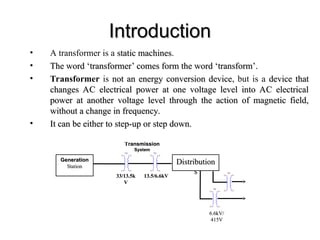
• It can be either to step-up or step down.
It can be either to step-up or step down.
Generation
Generation
Station
Station
TX1 TX1
Distribution
Distribution
s
s TX1
TX1
T
Transmission
ransmission
System
System
33/13.5k
33/13.5k
V
V
13.5/6.6kV
13.5/6.6kV
6.6kV/
6.6kV/
415V
415V
3.
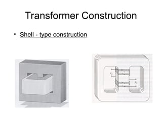
Transformer Construction
• Twotypes of iron-core construction:
a) Core - type construction
b) Shell - type construction
• Core - type construction
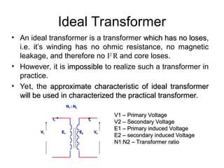
Ideal Transformer
• Anideal transformer is a transformer which has no loses
which has no loses,
i.e. it’s winding has no ohmic resistance, no magnetic
leakage, and therefore no I2
R and core loses.
• However, it is impossible
impossible to realize such a transformer in
practice.
• Yet, the approximate characteristic of ideal transformer
approximate characteristic of ideal transformer
will be used in characterized the practical transformer.
will be used in characterized the practical transformer.
V
V1
1 V
V2
2
N
N1
1 : N
: N2
2
E
E1
1 E
E2
2
I
I1
1 I
I2
2
V1 – Primary Voltage
V1 – Primary Voltage
V2 – Secondary Voltage
V2 – Secondary Voltage
E1 – Primary induced Voltage
E1 – Primary induced Voltage
E2 – secondary induced Voltage
E2 – secondary induced Voltage
N1:N2 – Transformer ratio
N1:N2 – Transformer ratio
6.
Transformer Equation
• Faraday’sLaw states that,
– If the flux passes through a coil of wire, a voltage will be
induced in the turns of wire. This voltage is directly
proportional to the rate of change in the flux with respect
of time.
If we have N
N turns of wire,
dt
t
d
Emf
V ind
ind
)
(
dt
t
d
N
Emf
V ind
ind
)
(
Lenz’s Law
7.
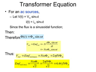
Transformer Equation
• Foran ac sources,
– Let V(t) = Vm sint
i(t) = im sint
Since the flux is a sinusoidal function;
Then:
Therefore:
Thus:
t
t m
sin
)
(
t
N
dt
t
d
N
Emf
V
m
m
ind
ind
cos
sin
m
m
ind
ind fN
N
Emf
V
2
(max)
m
m
m
rms
ind fN
fN
N
Emf
44
.
4
2
2
2
)
(
8.
Transformer Equation
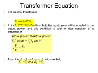
• Foran ideal transformer
• In the equilibrium condition, both the input power will be equaled to the
output power, and this condition is said to ideal condition of a
transformer.
• From the ideal transformer circuit, note that,
m
m
fN
E
fN
E
2
2
1
1
44
.
4
44
.
4
1
2
2
1
2
2
1
1 cos
cos
I
I
V
V
I
V
I
V
power
output
power
Input
………………… (i)
2
2
1
1 V
E
and
V
E
9.
Transformer Equation
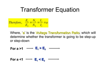
a
I
I
N
N
E
E
Therefore
1
2
2
1
2
1
,
Where,‘a
a’ is the Voltage Transformation Ratio
Voltage Transformation Ratio; which will
determine whether the transformer is going to be step-up
or step-down
E
E1
1 > E
> E2
2
For a >1
For a >1
For a <1
For a <1 E
E1
1 < E
< E2
2
10.
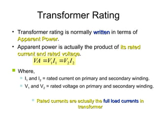
Transformer Rating
• Transformerrating is normally written
written in terms of
Apparent Power
Apparent Power.
• Apparent power is actually the product of its rated
its rated
current and rated voltage
current and rated voltage.
2
2
1
1 I
V
I
V
VA
Where,
I1 and I2 = rated current on primary and secondary winding.
V1 and V2 = rated voltage on primary and secondary winding.
Rated currents are actually the
Rated currents are actually the full load currents
full load currents in
in
transformer
transformer
11.
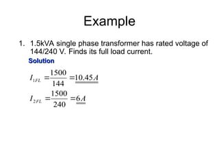
Example
1. 1.5kVA singlephase transformer has rated voltage of
144/240 V. Finds its full load current.
Solution
Solution
A
I
A
I
FL
FL
6
240
1500
45
.
10
144
1500
2
1
12.
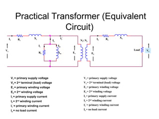
Practical Transformer (Equivalent
Circuit)
V1= primary supply voltage
V2 = 2nd
terminal (load) voltage
E1 = primary winding voltage
E2 = 2nd
winding voltage
I1 = primary supply current
I2 = 2nd
winding current
I1
’
= primary winding current
Io = no load current
V1 = primary supply voltage
V2 = 2nd
terminal (load) voltage
E1 = primary winding voltage
E2 = 2nd
winding voltage
I1 = primary supply current
I2 = 2nd
winding current
I1
’
= primary winding current
Io = no load current
V
V1
1
I
I1
1 R
R1
1
X
X1
1
R
RC
C
I
Ic
c
X
Xm
m
I
Im
m
I
Io
o
E
E1
1 E
E2
2
V
V2
2
I
I1
1
’
’
N
N1
1: N
: N2
2
R
R2
2
X
X2
2
Load
Load
I
I2
2
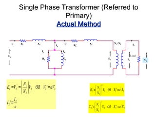
13.
Single Phase Transformer(Referred to
Primary)
Actual Method
Actual Method
2
2
2
2
2
2
1
2 '
' X
a
X
OR
X
N
N
X
2
2
2
2
2
2
1
2 '
' R
a
R
OR
R
N
N
R
V
V1
1
I
I1
1 R
R1
1 X
X1
1
R
RC
C
I
Ic
c
X
Xm
m
I
Im
m
I
Io
o
E
E1
1 E
E2
2 V
V2
2
I
I2
2
’
’ N
N1
1: N
: N2
2
R
R2
2
’
’ X
X2
2
’
’
Load
I
I2
2
a
I
I
aV
V
OR
V
N
N
V
E
2
2
2
2
2
2
1
'
2
1
'
'
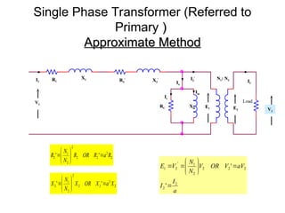
14.
Single Phase Transformer(Referred to
Primary )
)
Approximate Method
Approximate Method
2
2
2
2
2
2
1
2 '
' R
a
R
OR
R
N
N
R
2
2
2
2
2
2
1
2 '
' X
a
X
OR
X
N
N
X
V
V1
1
I
I1
1 R
R1
1
X
X1
1
R
RC
C
I
Ic
c
X
Xm
m
I
Im
m
I
Io
o
E
E1
1 E
E2
2 V
V2
2
I
I2
2
’
’ N
N1
1: N
: N2
2
R
R2
2
’
’
X
X2
2
’
’
Load
I
I2
2
a
I
I
aV
V
OR
V
N
N
V
E
2
2
2
2
2
2
1
'
2
1
'
'
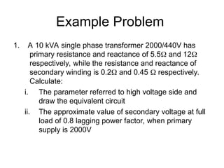
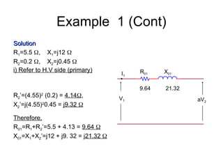
15.
Example Problem
1. A10 kVA single phase transformer 2000/440V has
primary resistance and reactance of 5.5 and 12
respectively, while the resistance and reactance of
secondary winding is 0.2 and 0.45 respectively.
Calculate:
i. The parameter referred to high voltage side and
draw the equivalent circuit
ii. The approximate value of secondary voltage at full
load of 0.8 lagging power factor, when primary
supply is 2000V
Example 1 (Cont)
A
V
VA
IFL5
2000
10
10 3
1
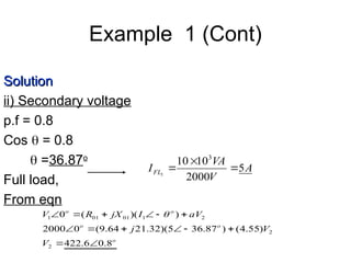
Solution
Solution
ii) Secondary voltage
p.f = 0.8
Cos = 0.8
=36.87o
Full load,
From eqn
o
o
o
o
o
V
V
j
aV
I
jX
R
V
8
.
0
6
.
422
)
55
.
4
(
)
87
.
36
5
)(
32
.
21
64
.
9
(
0
2000
)
)(
(
0
2
2
2
1
01
01
1
18.
Transformer Losses
• Generally,there are two types of losses;
i.
i. Iron losses
Iron losses :- occur in core parameters
ii.
ii. Copper losses
Copper losses :- occur in winding resistance
i.
i. Iron Losses
Iron Losses
ii
ii Copper Losses
Copper Losses
circuit
open
c
c
c
iron P
R
I
P
P
2
)
(
02
2
2
01
2
1
2
2
2
1
2
1
)
(
)
(
,
)
(
)
(
R
I
R
I
P
referred
if
or
P
R
I
R
I
P
P
cu
circuit
short
cu
copper
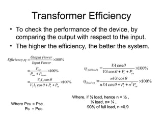
19.
Transformer Efficiency
• Tocheck the performance of the device, by
comparing the output with respect to the input.
• The higher the efficiency, the better the system.
%
100
cos
cos
%
100
%
100
,
2
2
2
2
cu
c
losses
out
out
P
P
I
V
I
V
P
P
P
Power
Input
Power
Output
Efficiency
%
100
cos
cos
%
100
cos
cos
2
)
(
)
(
cu
c
n
load
cu
c
load
full
P
n
P
nVA
nVA
P
P
VA
VA
Where, if ½ load, hence n = ½ ,
½ load, hence n = ½ ,
¼ load, n= ¼ ,
¼ load, n= ¼ ,
90% of full load, n =0.9
90% of full load, n =0.9
Where Pcu = Psc
Pc = Poc
20.
Voltage Regulation
• Thepurpose of voltage regulation is
basically to determine the percentage of
voltage drop between no load and full
load.
• Voltage Regulation can be determine
based on 3 methods:
a) Basic Defination
b) Short – circuit Test
c) Equivalent Circuit
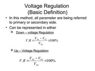
21.
Voltage Regulation
(Basic Definition)
•In this method, all parameter are being referred
to primary or secondary side.
• Can be represented in either
Down – voltage Regulation
%
100
.
NL
FL
NL
V
V
V
R
V
Up – Voltage Regulation
%
100
.
FL
FL
NL
V
V
V
R
V
22.
Tap Changer
A transformertap is a connection point
along a transformer winding that allows a
certain number of turns to be selected.
By this means, a transformer with a
variable turns ratio is produced, enabling
voltage regulation of the output. The tap
selection is made via a tap changer
mechanism.
23.
Three Phase Transformers
3 single phase transformers connected together
1.Star/Delta winding arrangements
2. Easy to replace failed units
Common core device
1. Lighter and cheaper than 3 individual units
2. 6 rather than 12 external connections
3. Whole transformer must be replaced if single
winding fails .
For both cases analysis procedure identical!


![transformhdhhjytbjguihgters_g_62[2].pptx](https://cdn.slidesharecdn.com/ss_thumbnails/transformersg622-250718173118-5265e8c2-thumbnail.jpg?width=640&height=640&fit=bounds)


