Downloaded 548 times

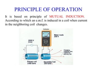
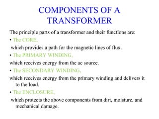


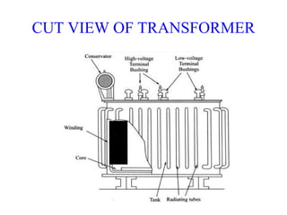
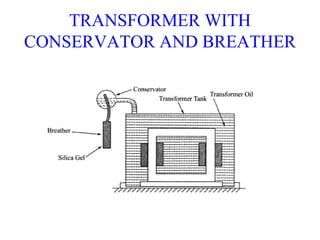


This document provides information about transformers, including their components, principles of operation, and applications. It discusses how transformers transfer electrical energy from one circuit to another through electromagnetic induction, changing the voltage and current magnitudes but not the frequency. The key components are the core, primary winding, and secondary winding. Transformers operate based on the principle of mutual induction between the windings. They are used in various applications like power transmission and audio/radio frequencies.


![Chapter_3-Transformers[1]-1.pdf](https://cdn.slidesharecdn.com/ss_thumbnails/chapter3-transformers1-1-230622173423-be6efc48-thumbnail.jpg?width=640&height=640&fit=bounds)


