More Related Content

PPTX
About the TRANSFORMERS and its working principle 
PPTX
Auto Transformers in Electrical Machines 
PPTX
1909023_EEE291_Three Phase Transformer.pptx 
PPTX
Transformer presentaton the the working principal.pptx 
PPT
B tech ee ii_ eee_ u-4_ transformer & electrical wiring_dipen patel 
PPTX

PPTX
Transformer its types ,working,basic principle.pptx 
PPT
OPERATION AND MAINTAINANCE OF DISTRIBUTION TRANSFORMER AND PREVENTIOMOF FAILURE Similar to Abb power transformer detail presentation.ppt

PDF
Module3- Transformer (1).pdf 
PPTX
ch4-transformer-and-dc-motor for ug .pptx 
PPTX

PPTX

PPT

PPTX
Transformers and its Types 
PDF
Transformers devices and its efficiency of it 
PPT
(2)OPERATING PRINCIPLES.ppt FOR STUDY PU 
PPTX
Transformers and common types of transformer 
PPTX
Transformer types presentation.................................................. 
PPTX
UNIT - II Transformers.pptx 
PPTX
UNIT - II Transformers.pptx 
PDF

PPTX

PPT
OPERATING PRINCIPLES OF TRANSFORMER AND CONSTRUCTION.ppt 
PPTX

PDF
Internship report report on harmonic analysis of transformer, internship repo... 
PPTX
Machines 1 2024-25, single transformers.pptx 
PDF
General concepts, construction and design of transformer 
PPTX
Recently uploaded

PDF
NS unit wise unit wise 1 -5 so prepare,. 
PDF
Plasticity and Structure of Soil/Atterberg Limits.pdf 
PPTX
Presentation-WPS Office.pptx afgouvhyhgfccf 
PDF
Microeconomics Theory and Market Structure.pdf 
PPTX
Optimizing the ELBO Objective: A Comparative Study of RNN, LSTM, and GRU Arch... 
PPTX
Optimum mesh size for various fishing gears by B2B.pptx 
PPTX
Batch-1(End Semester) Student Of Shree Durga Tech. PPT.pptx 
PDF
Rajesh Prasad- Brief Profile with educational, professional highlights 
PDF
engineering management chapter 5 ppt presentation 
PDF
PROBLEM SLOVING AND PYTHON PROGRAMMING UNIT 3.pdf 
PPTX
Why Most SAP PM Implementations Fail — And How High-Reliability Plants Fix It 
PPTX
Every Plant Has a Weak Link: How AI CMMS Exposes Hidden Reliability Risks 
PPTX
unit v awp IN ANTENNA AND WAVE PROP IN JNTUH 
PDF
Industrial Tools Manufacturers In India : Torso Tools 
PDF
MoD_2.pptx solid rockets of the rocket.pdf 
PPTX
A professional presentation on Cosmos Bank Heist 
PPTX
ME3592 - Metrology and Measurements - Unit - 1 - Lecture Notes 
PDF
DAA Lab Manual ssit -kavya r.pdf or Digital Design and Analysis of Algorithm ... 
PDF
(en/zhTW) Heterogeneous System Architecture: Design & Performance 
PDF
Computer Network Lab Manual ssit -kavya r.pdf or Computer Network Lab Manual ... Abb power transformer detail presentation.ppt
- 1.
- 2.
- 3.
- 4.
©
ABB
Power
Technology
1_114Q07-
4
-
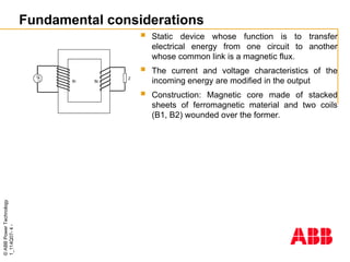
Fundamental considerations
Staticdevice whose function is to transfer
electrical energy from one circuit to another
whose common link is a magnetic flux.
The current and voltage characteristics of the
incoming energy are modified in the output
Construction: Magnetic core made of stacked
sheets of ferromagnetic material and two coils
(B1, B2) wounded over the former.
G Z
B1 B2
- 5.
©
ABB
Power
Technology
1_114Q07-
5
-
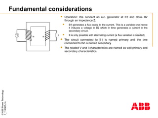
Fundamental considerations
G Z
B1B2
Operation: We connect an a.c. generator at B1 and close B2
through an impedance Z.
B1 generates a flux owing to the current. This is a variable one hence
it induces a voltage in B2 which in time generates a current in the
secondary circuit.
It is only possible with alternating current (a flux variation is needed)
The circuit connected to B1 is named primary and the one
connected to B2 is named secondary
The related V and I characteristics are named as well primary and
secondary characteristics.
- 6.
©
ABB
Power
Technology
1_114Q07-
6
-
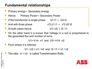
Fundamental relationships
Primaryenergy Secondary energy
Hence Primary Power Secondary Power
If the transformer is single phase U1 I1 U2 I2
And with three phase √3 U1 I1 √3 U2 I2
At both cases hence U1/ U2 I2 / I1
On the other hand it is known that Voltage in a coil is proportional to
the generated flux and number of turns
U1= k1 n1 and U2= k1 n2
From where it is inferred:
U1 / U2 = n1 / n2 and I2 / I1 = n1 / n2
The ratio n1 / n2 is called Transformation Ratio
- 7.
©
ABB
Power
Technology
1_114Q07-
7
-
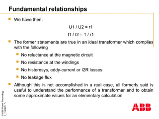
We havethen:
U1 / U2 = r1
I1 / I2 = 1 / r1
The former statements are true in an ideal transformer which complies
with the following
No reluctance at the magnetic circuit
No resistance at the windings
No histeresys, eddy-current or I2R losses
No leakage flux
Although this is not accomplished in a real case, all formerly said is
useful to understand the performance of a transformer and to obtain
some approximate values for an elementary calculation
Fundamental relationships
- 8.
©
ABB
Power
Technology
1_114Q07-
8
-
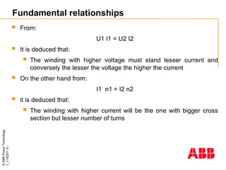
From:
U1 I1= U2 I2
It is deduced that:
The winding with higher voltage must stand lesser current and
conversely the lesser the voltage the higher the current
On the other hand from:
I1 n1 = I2 n2
it is deduced that:
The winding with higher current will be the one with bigger cross
section but lesser number of turns
Fundamental relationships
- 9.
©
ABB
Power
Technology
1_114Q07-
9
-
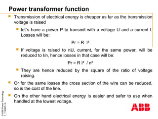
Power transformer function
Transmission of electrical energy is cheaper as far as the transmission
voltage is raised
let´s have a power P to transmit with a voltage U and a current I.
Losses will be:
Pr = R I²
If voltage is raised to nU, current, for the same power, will be
reduced to I/n, hence losses in that case will be:
Pr = R I² / n²
They are hence reduced by the square of the ratio of voltage
raising.
Or for the same losses the cross section of the wire can be reduced,
so is the cost of the line.
On the other hand electrical energy is easier and safer to use when
handled at the lowest voltage.
- 10.
©
ABB
Power
Technology
1_114Q07-
10
-
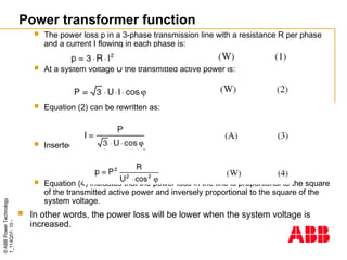
The powerloss p in a 3-phase transmission line with a resistance R per phase
and a current I flowing in each phase is:
At a system voltage U the transmitted active power is:
Equation (2) can be rewritten as:
Inserted in the equation (1) gives:
Equation (4) indicates that the power loss in the line is proportional to the square
of the transmitted active power and inversely proportional to the square of the
system voltage.
In other words, the power loss will be lower when the system voltage is
increased.
Power transformer function
- 11.
©
ABB
Power
Technology
1_114Q07-
11
-
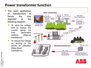
The mainapplication
of transformers is
hence the one
depicted at the
following diagram :
To raise the voltage
and to reduce the
current going out
from generation
stations (Step-up
substations).
To reduce the voltage
on arriving to the
points of utilization
(Step-Down
substations).
Power transformer function
- 12.
- 13.
©
ABB
Power
Technology
1_114Q07-
13
-
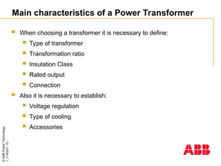
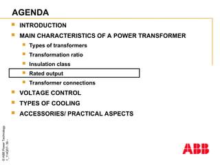
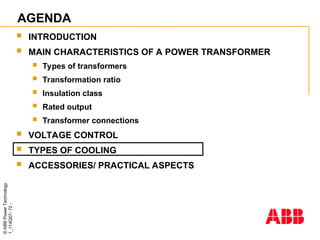
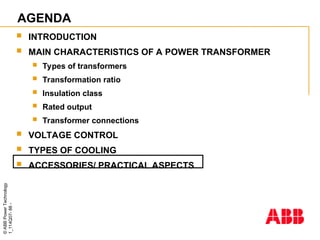
Main characteristics ofa Power Transformer
When choosing a transformer it is necessary to define:
Type of transformer
Transformation ratio
Insulation Class
Rated output
Connection
Also it is necessary to establish:
Voltage regulation
Type of cooling
Accessories
- 14.
- 15.
- 16.
©
ABB
Power
Technology
1_114Q07-
16
-
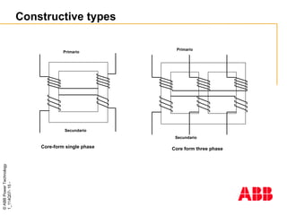
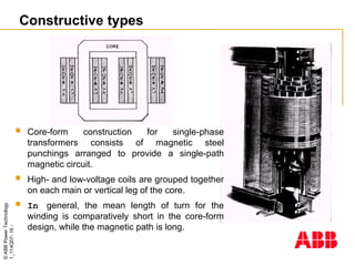
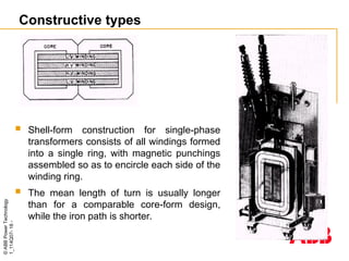
Constructive types
Core-formconstruction for single-phase
transformers consists of magnetic steel
punchings arranged to provide a single-path
magnetic circuit.
High- and low-voltage coils are grouped together
on each main or vertical leg of the core.
In general, the mean length of turn for the
winding is comparatively short in the core-form
design, while the magnetic path is long.
- 17.
- 18.
©
ABB
Power
Technology
1_114Q07-
18
-
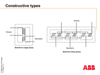
Constructive types
Shell-formconstruction for single-phase
transformers consists of all windings formed
into a single ring, with magnetic punchings
assembled so as to encircle each side of the
winding ring.
The mean length of turn is usually longer
than for a comparable core-form design,
while the iron path is shorter.
- 19.
©
ABB
Power
Technology
1_114Q07-
19
-
Constructive types
Inthe design of a particular transformer many factors such as insulation stress,
mechanical stress, heat distribution, weight and cost must be balanced and
compromised.
It appears that, for well-balanced design, both core-form and shell-form units have their
respective fields of applicability determined by kva and kv rating.
In the larger sizes, shell-form construction is quite appropriate; the windings and
magnetic iron can be assembled on a steel base structure, with laminations laid in
horizontally to link and surround the windings.
A close-fitting tank member is then dropped over the core and coil assembly and welded to
the steel base, completing the tank assembly and also securing the core to the base member.
- 20.
- 21.
- 22.
©
ABB
Power
Technology
1_114Q07-
22
-
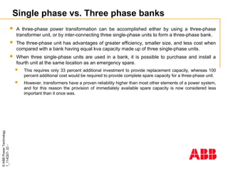
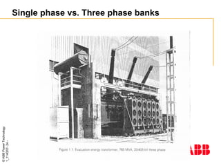
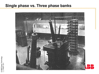
Single phase vs.Three phase banks
A three-phase power transformation can be accomplished either by using a three-phase
transformer unit, or by inter-connecting three single-phase units to form a three-phase bank.
The three-phase unit has advantages of greater efficiency, smaller size, and less cost when
compared with a bank having equal kva capacity made up of three single-phase units.
When three single-phase units are used in a bank, it is possible to purchase and install a
fourth unit at the same location as an emergency spare.
This requires only 33 percent additional investment to provide replacement capacity, whereas 100
percent additional cost would be required to provide complete spare capacity for a three-phase unit.
However, transformers have a proven reliability higher than most other elements of a power system,
and for this reason the provision of immediately available spare capacity is now considered less
important than it once was.
- 23.
©
ABB
Power
Technology
1_114Q07-
23
-
Single phase vs.Three phase banks
Three-phase units are quite generally used in the highest of circuit
ratings, with no on-the-spot spare transformer capacity provided.
In these cases parallel or interconnected circuits of the system may
provide emergency capacity, or, for small and medium size
transformers, portable substations can provide spare capacity on short
notice.
If transportation or rigging facilities should not be adequate to handle
the required transformer capacity as a single unit, a definite reason of
course develops for using three single-phase units.
- 24.
- 25.
- 26.
©
ABB
Power
Technology
1_114Q07-
26
-
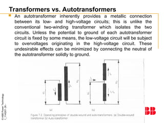
Transformers vs. Autotransformers
An autotransformer inherently provides a metallic connection
between its low- and high-voltage circuits; this is unlike the
conventional two-winding transformer which isolates the two
circuits. Unless the potential to ground of each autotransformer
circuit is fixed by some means, the low-voltage circuit will be subject
to overvoltages originating in the high-voltage circuit. These
undesirable effects can be minimized by connecting the neutral of
the autotransformer solidly to ground.
- 27.
©
ABB
Power
Technology
1_114Q07-
27
-
Transformers vs. Autotransformers
The autotransformer has advantages of:
lower cost,
higher efficiency
better regulation
It has disadvantages including:
low reactance which may make it subject to excessive short-circuit currents
the arrangement of taps is more complicated
the low- and high-voltage circuits cannot be isolated
the two circuits must operate with no angular phase displacement unless a zig-zag
connection is introduced.
The advantages of lower cost and improved efficiency become less apparent as
the transformation ratio increases, so that autotransformers for power purposes
are usually used for low transformation ratios, rarely exceeding 2 to 1.
- 28.
©
ABB
Power
Technology
1_114Q07-
28
-
Transformers vs. Autotransformers
Three-phase autotransformers for power service are usually star-star
connected with the neutral grounded, and in most of these cases it is
desirable to have a third winding on the core delta-connected so as to
carry the third harmonic component of exciting current.
This winding could be very small in capacity if it were required to carry
only harmonic currents, but its size is increased by the requirement that it
carry high currents during system ground faults.
A widely used rule sets the delta-winding rating at 35 percent of the
autotransformer equivalent two-winding kva rating (not circuit kva rating).
Since it is necessary in most cases to have a delta-connected tertiary
winding, it is often advantageous to design this winding so that load
can be taken from it. This results in a three-winding autotransformer
with terminals to accommodate three external circuits.
- 29.
- 30.
©
ABB
Power
Technology
1_114Q07-
30
-
Transformation ratio
Primaryvoltage : The most usual value of the voltage at the point of
the network where the transformer is going to be connected
When this voltage is expected to vary it could be necessary that the
transformer is equipped with an on load tap changer
Secondary voltage: The desired value at the secondary network
where the transformer will be connected.
- 31.
©
ABB
Power
Technology
1_114Q07-
31
-
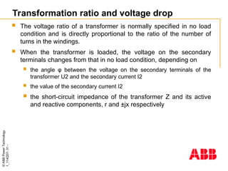
Transformation ratio andvoltage drop
The voltage ratio of a transformer is normally specified in no load
condition and is directly proportional to the ratio of the number of
turns in the windings.
When the transformer is loaded, the voltage on the secondary
terminals changes from that in no load condition, depending on
the angle φ between the voltage on the secondary terminals of the
transformer U2 and the secondary current I2
the value of the secondary current I2
the short-circuit impedance of the transformer Z and its active
and reactive components, r and ±jx respectively
- 32.
©
ABB
Power
Technology
1_114Q07-
32
-
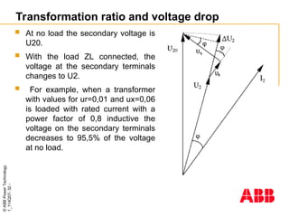
Transformation ratio andvoltage drop
At no load the secondary voltage is
U20.
With the load ZL connected, the
voltage at the secondary terminals
changes to U2.
For example, when a transformer
with values for ur=0,01 and ux=0,06
is loaded with rated current with a
power factor of 0,8 inductive the
voltage on the secondary terminals
decreases to 95,5% of the voltage
at no load.
- 33.
©
ABB
Power
Technology
1_114Q07-
33
-
Transformation ratio andvoltage drop
Users and installation planners are recommended to take the
variation of the secondary voltage during loading into account when
specifying the transformer data.
This may be especially important for example in a case where a
large motor represents the main load of the transformer.
The highly inductive starting current of the motor may then be
considerably higher than the rated current of the transformer.
Consequently there may be a considerable voltage drop through the
transformer.
If the feeding power source is weak, this will contribute to an even
lower voltage on the secondary side of the transformer.
- 34.
©
ABB
Power
Technology
1_114Q07-
34
-
Short circuit impedance
Users have sometimes particular requirements regarding the short-circuit
impedance. Such requirements may be determined by:
parallel operation with existing units,
limitation of voltage drop,
limitation of short-circuit currents.
The transformer designer can meet the requirements in different ways:
The size of the core cross-section. A large cross-section gives a low
impedance and vice versa,
A tall transformer gives a low impedance and vice versa.
For each transformer there is, however, a smaller range which gives the
optimum transformer from an economic point of view, that is the lowest
sum of the manufacturing costs and the capitalised value of the losses.
- 35.
©
ABB
Power
Technology
1_114Q07-
35
-
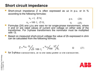
Short circuit impedance
Short-circuit impedance Z is often expressed as uz in p.u. or in %
according to the following formulas:
Formulas (24) and (25) are valid for for single-phase transformers, where
Ir and Ur are rated values of current and voltage on either side of the
transformer. For 3-phase transformers the nominator must be multiplied
with √3.
Based on measured short-circuit voltage the value of Zk expressed in ohm
can be calculated from the following formula:
for 3-phase transformers. Sr is the rated power of the transformer.
- 36.
- 37.
- 38.
©
ABB
Power
Technology
1_114Q07-
38
-
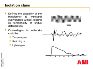
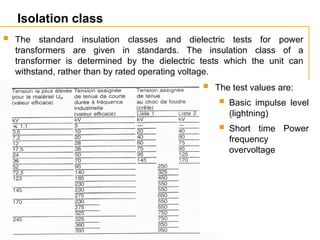
Isolation class
Thestandard insulation classes and dielectric tests for power
transformers are given in standards. The insulation class of a
transformer is determined by the dielectric tests which the unit can
withstand, rather than by rated operating voltage.
The test values are:
Basic impulse level
(lightning)
Short time Power
frequency
overvoltage
- 39.
- 40.
©
ABB
Power
Technology
1_114Q07-
40
-
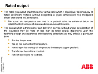
Rated output
Therated kva output of a transformer is that load which it can deliver continuously at
rated secondary voltage without exceeding a given temperature rise measured
under prescribed test conditions.
The actual test temperature rise may, in a practical case, be somewhat below the
established limit because of design and manufacturing tolerances.
The output which a transformer can deliver in service without undue deterioration of
the insulation may be more or less than its rated output, depending upon the
following design characteristics and operating conditions as they exist at a particular
time:
Ambient temperature.
Top-oil rise over ambient temperature.
Hottest-spot rise over top-oil temperature (hottest-spot copper gradient).
Transformer thermal time constant.
Ratio of load loss to no-load loss.
- 41.
©
ABB
Power
Technology
1_114Q07-
41
-
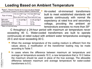
Loading Based onAmbient Temperature
Air-cooled oil-immersed transformers
built to meet established standards will
operate continuously with normal life
expectancy at rated kva and secondary
voltage, providing the ambient air
temperature averages no more than 30º
C throughout a 24-hour period with maximum air temperature never
exceeding 40 C. Water-cooled transformers are built to operate
continuously at rated output with ambient water temperatures averaging
25 C and never exceeding 30 C.
When the average temperature of the cooling medium is different from the
values above, a modification of the transformer loading may be made
according to Table 7.
In cases where the difference between maximum air temperature and
average air temperature exceeds 10 C, a new temperature that is 10 C below
the maximum should be used in place of the true average. The allowable
difference between maximum and average temperature for water-cooled
transformers is 5 C.
- 42.
©
ABB
Power
Technology
1_114Q07-
42
-
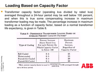
Loading Based onCapacity Factor
Transformer capacity factor (operating kva divided by rated kva)
averaged throughout a 24-hour period may be well below 100 percent,
and when this is true some compensating increase in maximum
transformer loading may be made. The percentage increase in maximum
loading as a function of capacity factor, based on a normal transformer
life expectancy, is given in Table 8.
- 43.
©
ABB
Power
Technology
1_114Q07-
43
-
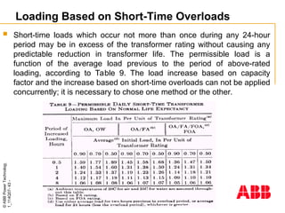
Loading Based onShort-Time Overloads
Short-time loads which occur not more than once during any 24-hour
period may be in excess of the transformer rating without causing any
predictable reduction in transformer life. The permissible load is a
function of the average load previous to the period of above-rated
loading, according to Table 9. The load increase based on capacity
factor and the increase based on short-time overloads can not be applied
concurrently; it is necessary to chose one method or the other.
- 44.
©
ABB
Power
Technology
1_114Q07-
44
-
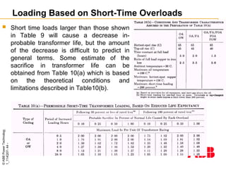
Loading Based onShort-Time Overloads
Short time loads larger than those shown
in Table 9 will cause a decrease in-
probable transformer life, but the amount
of the decrease is difficult to predict in
general terms. Some estimate of the
sacrifice in transformer life can be
obtained from Table 10(a) which is based
on the theoretical conditions and
limitations described in Table10(b).
- 45.
©
ABB
Power
Technology
1_114Q07-
45
-
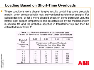
Loading Based onShort-Time Overloads
These conditions were chosen to give results containing some probable
margin, when compared with most conventional transformer designs. For
special designs, or for a more detailed check on some particular unit, the
hottest-spot copper temperature can be calculated by the method shown
in section 19, and the probable sacrifice in transformer life can then be
estimated from Table 11.
- 46.
©
ABB
Power
Technology
1_114Q07-
46
-
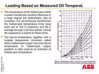
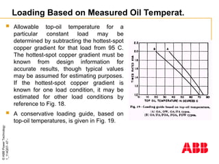
Loading Based onMeasured Oil Temperat.
The temperature of the hottest-spot within
a power transformer winding influences to
a large degree the deterioration rate of
insulation. For oil-immersed transformers
the hottest-spot temperature limits have
been set at 105 C maximum and 95 C
average through a 24 hour period; normal
life expectancy is based on these limits.
The top-oil temperature, together with a
suitable temperature increment called
either hottest-spot copper rise over top-oil
temperature or hottest-spot copper
gradient, is often used as an indication of
hottest-spot temperature.
- 47.
©
ABB
Power
Technology
1_114Q07-
47
-
Loading Based onMeasured Oil Temperat.
Allowable top-oil temperature for a
particular constant load may be
determined by subtracting the hottest-spot
copper gradient for that load from 95 C.
The hottest-spot copper gradient must be
known from design information for
accurate results, though typical values
may be assumed for estimating purposes.
If the hottest-spot copper gradient is
known for one load condition, it may be
estimated for other load conditions by
reference to Fig. 18.
A conservative loading guide, based on
top-oil temperatures, is given in Fig. 19.
- 48.
©
ABB
Power
Technology
1_114Q07-
48
-
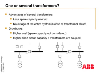
One or severaltransformers?
Advantages of several transformers:
Less spare capacity needed
No outage of the entire system in case of transformer failure
Drawbacks:
Higher cost (spare capacity not considered)
Higher short circuit capacity if transformers are coupled
......
......
......
......
- 49.
©
ABB
Power
Technology
1_114Q07-
49
-
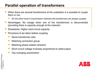
Parallel operation oftransformers
When there are several transformers at the substation it is possible to couple
them or not.
On the other hand in transmission networks the transformers are always coupled.
Advantages: No outage when one of the transformers is disconnected
(providing there is capacity enough at the network)
Drawbacks: Higher short circuit capacity
Provisions to be taken before coupling:
Same transformer ratio
Matching connection group
Matching phase rotation direction
Short circuit voltage inversely proportional to rated output
Tap changing coordination
- 50.
- 51.
©
ABB
Power
Technology
1_114Q07-
51
-
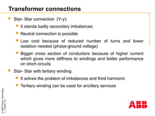
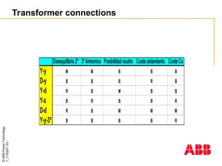
Transformer connections
Star-Star connection (Y-y):
It stands badly secondary imbalances
Neutral connection is possible
Low cost because of reduced number of turns and lower
isolation needed (phase-ground voltage)
Bigger cross section of conductors because of higher current
which gives more stiffness to windings and better performance
on short circuits
Star- Star with tertiary winding:
It solves the problem of imbalances and third harmonic
Tertiary winding can be used for ancillary services
- 52.
©
ABB
Power
Technology
1_114Q07-
52
-
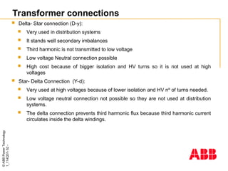
Delta- Starconnection (D-y):
Very used in distribution systems
It stands well secondary imbalances
Third harmonic is not transmitted to low voltage
Low voltage Neutral connection possible
High cost because of bigger isolation and HV turns so it is not used at high
voltages
Star- Delta Connection (Y-d):
Very used at high voltages because of lower isolation and HV nº of turns needed.
Low voltage neutral connection not possible so they are not used at distribution
systems.
The delta connection prevents third harmonic flux because third harmonic current
circulates inside the delta windings.
Transformer connections
- 53.
- 54.
- 55.
- 56.
©
ABB
Power
Technology
1_114Q07-
56
-
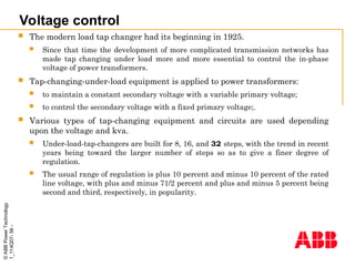
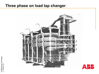
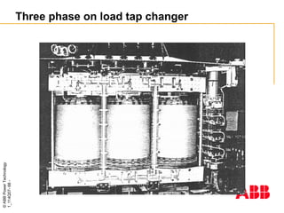
Voltage control
Themodern load tap changer had its beginning in 1925.
Since that time the development of more complicated transmission networks has
made tap changing under load more and more essential to control the in-phase
voltage of power transformers.
Tap-changing-under-load equipment is applied to power transformers:
to maintain a constant secondary voltage with a variable primary voltage;
to control the secondary voltage with a fixed primary voltage;.
Various types of tap-changing equipment and circuits are used depending
upon the voltage and kva.
Under-load-tap-changers are built for 8, 16, and 32 steps, with the trend in recent
years being toward the larger number of steps so as to give a finer degree of
regulation.
The usual range of regulation is plus 10 percent and minus 10 percent of the rated
line voltage, with plus and minus 71/2 percent and plus and minus 5 percent being
second and third, respectively, in popularity.
- 57.
©
ABB
Power
Technology
1_114Q07-
57
-
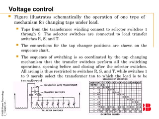
Voltage control
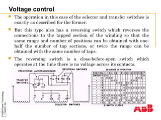
Figureillustrates schematically the operation of one type of
mechanism for changing taps under load.
Taps from the transformer winding connect to selector switches 1
through 9. The selector switches are connected to load transfer
switches R, S, and T.
The connections for the tap changer positions are shown on the
sequence chart.
The sequence of switching is so coordinated by the tap changing
mechanism that the transfer switches perform all the switching
operations, opening before and closing after the selector switches.
All arcing is thus restricted to switches R, S, and T, while switches 1
to 9 merely select the transformer tap to which the load is to be
transferred.
- 58.
©
ABB
Power
Technology
1_114Q07-
58
-
Voltage control
Whenthe tap changer is on odd-numbered positions, the
preventive auto-transformer is short-circuited.
On all even- numbered positions, the preventive auto-
transformer bridges two transformer taps.
In this position, the relatively high reactance of the preventive
auto-transformer to circulating currents between adjacent taps
prevents damage to the transformer winding, while its relatively
low impedance to the load current permits operation on this
position to obtain voltages midway between the transformer
taps.
- 59.
©
ABB
Power
Technology
1_114Q07-
59
-
Voltage control
Theoperation in this case of the selector and transfer switches is
exactly as described for the former.
But this type also has a reversing switch which reverses the
connections to the tapped section of the winding so that the
same range and number of positions can be obtained with one-
half the number of tap sections, or twice the range can be
obtained with the same number of taps.
The reversing switch is a close-before-open switch which
operates at the time there is no voltage across its contacts.
- 60.
©
ABB
Power
Technology
1_114Q07-
60
-
Voltage control
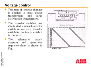
Thistype of load tap changer
is applied to small power
transformers and large
distribution transformers.
The transfer switches are
eliminated, and each selector
switch serves as a transfer
switch for the tap to which it
is connected.
The schematic circuit
diagram and operations
sequence chart is shown in
Fig.
- 61.
- 62.
©
ABB
Power
Technology
1_114Q07-
62
-
3
3
6
5
5
6
4
4
Impar
Par
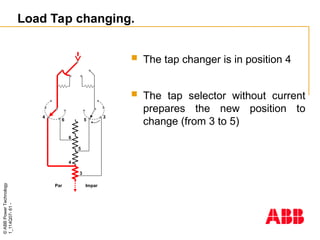
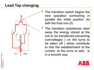
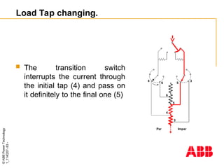
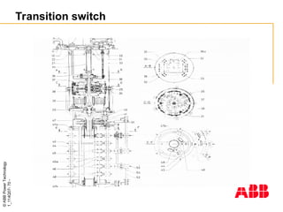
The transitionswitch begins the
new operation connecting in
parallel the initial position (4)
with the final one (5)
The transition resistances clear
away the energy stored at the
coil to be transferred preventing
overvoltages ( on the turns to
be taken off ) either contribute
to that the establishment of the
current, at the turns to add, is
in a smooth way.
Load Tap changing.
- 63.
- 64.
- 65.
- 66.
- 67.
- 68.
- 69.
- 70.
- 71.
- 72.
- 73.
©
ABB
Power
Technology
1_114Q07-
73
-
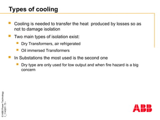
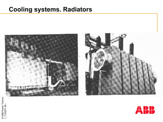
Types of cooling
Cooling is needed to transfer the heat produced by losses so as
not to damage isolation
Two main types of isolation exist:
Dry Transformers, air refrigerated
Oil immersed Transformers
In Substations the most used is the second one
Dry type are only used for low output and when fire hazard is a big
concern
- 74.
©
ABB
Power
Technology
1_114Q07-
74
-
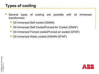
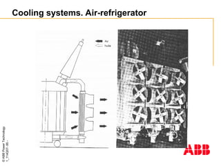
Types of cooling
Several types of cooling are possible with oil immersed
transformers:
Oil immersed Self cooled (ONAN)
Oil Immersed Self Cooled/Forced-Air Cooled (ONAF)
Oil immersed Forced cooled/Forced air cooled (OFAF)
Oil immersed Water cooled (ONWN-OFWF)
- 75.
©
ABB
Power
Technology
1_114Q07-
75
-
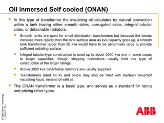
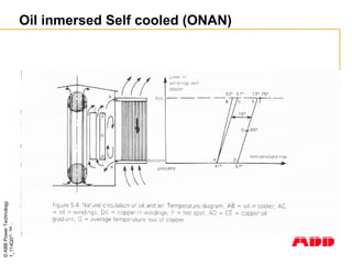
Oil inmersed Selfcooled (ONAN)
In this type of transformer the insulating oil circulates by natural convection
within a tank having either smooth sides, corrugated sides, integral tubular
sides, or detachable radiators.
Smooth tanks are used for small distribution transformers but because the losses
increase more rapidly than the tank surface area as kva capacity goes up, a smooth
tank transformer larger than 50 kva would have to be abnormally large to provide
sufficient radiating surface.
Integral tubular-type construction is used up to about 3000 kva and in some cases
to larger capacities, though shipping restrictions usually limit this type of
construction at the larger ratings.
Above 3000 kva detachable radiators are usually supplied.
Transformers rated 46 kv and below may also be filled with Inerteen fire-proof
insulating liquid, instead of with oil.
The ONAN transformer is a basic type, and serves as a standard for rating
and pricing other types.
- 76.
- 77.
©
ABB
Power
Technology
1_114Q07-
77
-
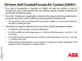
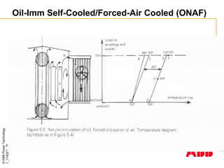
Oil-Imm Self-Cooled/Forced-Air Cooled(ONAF)
This type of transformer is basically an ONAN unit with the addition of fans to
increase the rate of heat transfer from the cooling surfaces, thereby increasing the
permissible transformer output.
The ONAF transformer is applicable in situations that require short-time peak loads to
be carried recurrently, without affecting normal expected transformer life.
This transformer may be purchased with fans already installed, or it may be purchased with
the option of adding fans later.
The higher kva capacity attained by the use of fans may be calculated as follows :
For 2500 kva (OA) and below: kva (FA)=l.l5Xkva(OA).
For 2501 to 9999 kva (OA) single-phase or 11 999 kva (OA) three-phase : kva (FA) = 1.25
X kva (OA).
For 10 000 kva (OA) single-phase and 12 000 kva (OA) three-phase, and above : kva (FA)
= 1.333Xkva (OA). (22)
These ratings are standardized, and are based on a hottest-spot copper temperature of 65
degrees C above 30 degrees C average ambient.
- 78.
- 79.
©
ABB
Power
Technology
1_114Q07-
79
-
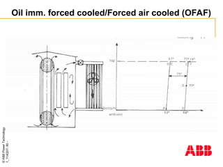
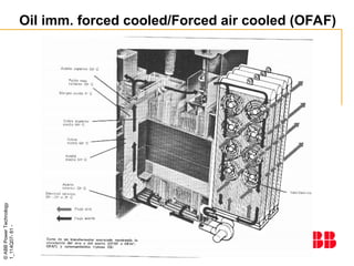
Oil imm. forcedcooled/Forced air cooled (OFAF)
The rating of an oil-immersed transformer may be increased from its OA
rating by the addition of some combination of fans and oil pumps.
Such transformers are normally built in the range 10 000 kva (OA) single-
phase or 12 000 kva (OA) three-phase, and above.
Increased ratings are defined as two steps, 1.333 and 1.667 times the OA rating
respectively.
Automatic controls responsive to oil temperature are normally used to start the
fans and pumps in a selected sequence as transformer loading increases.
A variation of this is a type of transformer which is intended for use only
when both oil pumps and fans are operating, under which condition any load
up to full rated kva may be carried.
Some designs are capable of carrying excitation current with no fans or pumps in
operation, but this is not universally true. Heat transfer from oil to air is
accomplished in external oil-to-air heat exchangers.
- 80.
- 81.
- 82.
©
ABB
Power
Technology
1_114Q07-
82
-
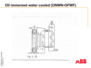
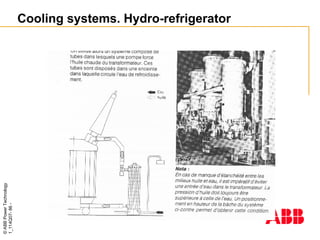
Oil immersed watercooled (ONWN-OFWF)
OW-Oil-Immersed Water-Cooled
In this type of water-cooled transformer, the cooling water runs
through coils of pipe which are in contact with the insulating oil of
the transformer.
The oil flows around the outside of these pipe coils by natural
convection, thereby effecting the desired heat transfer to the cooling
water. This type has no self-cooled rating.
FOW-Oil-Immersed Forced-Oil-Cooled With Forced-Water
Cooler-External oil-to-water heat exchangers are used in this type
of unit to transfer heat from oil to cooling water.
- 83.
- 84.
- 85.
- 86.
- 87.
- 88.
- 89.
- 90.
- 91.
©
ABB
Power
Technology
1_114Q07-
91
-
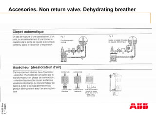
Accesories. Gas actuatedrelay (Buchholz)
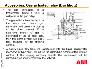
A heavy liquid flow from the transformer into the liquid conservator
(conservator type only), will cause the immediate closing of the tripping
contact. If the tripping contacts operate the transformer will be
immediately disconnected from the network.
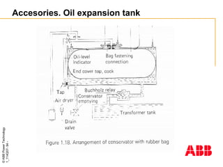
The gas generated in a
transformer during a fault is
collected in the gas relay.
The gas will displace the liquid in
the relay and minor gas
generation will cause the closing
of the alarm contact. If an
extensive amount of gas is
generated or the oil level falls,
then the alarm contact will close
first, followed by the tripping
contact.
- 92.
©
ABB
Power
Technology
1_114Q07-
92
-
Accesories. Gas actuatedrelay (Buchholz)
Operation of some protective equipment such as gas relay or
differential relay does not always mean that the transformer is
damaged.
The gas relay can operate for example when:
An air bubble has been left under the transformer cover. An air bubble is
colourless and odourless.
A short-circuit current has passed the transformer. No gas bubbles.
However if the gas has colour or smell, the transformer is damaged.
- 93.
- 94.
- 95.
- 96.
- 97.
- 98.
- 99.
©
ABB
Power
Technology
1_114Q07-
99
-
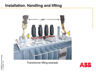
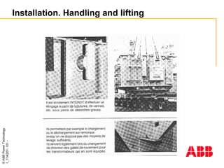
Installation. Handling andlifting
Only approved and suitable lifting equipment shall be used.
Use a forklift only on transport pallets or transformer bottom.
Do not apply load to corrugated fins or radiators and their supports.
Use the provided lifting lugs only.
When lifting a transformer with cable boxes on the cover, special
care must be taken.
When hydraulic jacks are used, only provided jacking points shall
be used, and in such a way that twisting forces on the transformer
tank are avoided.
- 100.
- 101.
- 102.
©
ABB
Power
Technology
1_114Q07-
102
-
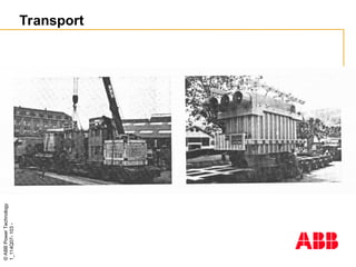
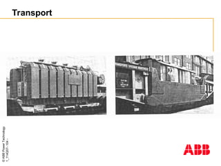
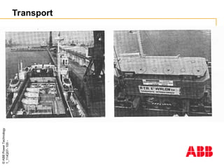
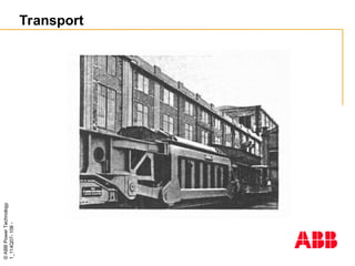
Transport
The transformeris supplied filled with liquid and normally all
accessories fitted, except for the largest units. The radiators may be
dismantled during transport.
During transport the following should be considered:
Angle of tilting exceeding 10º must be specified in the contract,
Prevention of damage to bushings, corrugated panels or
radiators and accessories,
Larger transformers should preferably be positioned with the
longitudinal axis in the direction of movement,
Secure against movement by means of e.g. wooden blocks and
lashes,
Adapt vehicle speed to the road conditions,
Vehicle capacity shall be adequate for the transport weight of
the transformer,
- 103.
- 104.
- 105.
- 106.
- 107.
©
ABB
Power
Technology
1_114Q07-
107
-
Maintenance
Inspection andmaintenance during operation
Inspection during operation shall only be performed after taking
safety measures into consideration:
If there is a maximum indicator on the thermometer the
maximum temperature should be recorded,
Inspection for contamination, especially on bushings,
Inspection of surface condition,
Dehydrating breather. The silicagel shall be changed when
approx. 2/3 of the silica gel has changed from blue to red colour
(old type), or from pink to white, respectively. (Conservator type
only),
Inspection for liquid leakages.
For personal safety reasons, only a limited amount of maintenance
activities should be performed on the transformer when it is in
operation.
- 108.
©
ABB
Power
Technology
1_114Q07-
108
-
Maintenance
Inspection andmaintenance during downtime
Before starting maintenance work, the transformer has to be
disconnected from the network and earthed. When the
disconnectors have been opened, they shall be locked in open
position to prevent them inadvertently closing during maintenance
work.
Items to be considered are:
Bushing gaskets; if leaks occur, tightening usually will help, if the
gasket has lost its elasticity, it must be replaced. The reason for
loss of elasticity can be excessive heating or aging,
Cover gaskets, valves and gaskets of the tap changer. If there
are leaks, tightening will usually help,
Welded joints. Leaking joints can be repaired only by welding. A
skilled welder and a welding instruction are required.,
- 109.
©
ABB
Power
Technology
1_114Q07-
109
-
Maintenance
Cleaning contaminatedbushings (cleaning agent e.g.
methylated spirit),
Cleaning glasses on gas relay, thermometer and liquid level
indicator,
Functional inspection of applicable accessories,
Move tap changer through all positions a few times, all types of
tap changers,
Liquid sampling from bottom drain valve for larger units as
required,
Check drying material in the dehydrating breather. (Conservator
type only),
Amend surface treatment defects.
In heavily contaminated installations more frequent inspections may
be needed.
- 110.
©
ABB
Power
Technology
1_114Q07-
110
-
Maintenance. Transformer liquidand insulation
The task of liquid in a transformer is to act as an electrical insulation
and to transfer heat from the transformer’s active parts into coolers.
Liquid acts as a good electrical insulation only as long as it is
satisfactorily dry and clean.
Humidity balance between the oil and the insulation implies that
most of the humidity will gather in the paper insulation.
Testing of liquid in transformers should normally be performed 12
months after filling or refilling, subsequently every six years.
Testing of oil in on load tap changers must be performed according
to the tap changer supplier’s recommendations.
To take liquid samples from hermetically sealed transformers is
normally not necessary. The liquid in this type of transformers is not
in contact with the atmosphere, and less exposed to moisture.
Especially for large transformers, liquid regeneration may be
economically motivated. Liquid regeneration implies drying, filtering,
de-gassing and possibly addition of inhibitor.
- 111.
©
ABB
Power
Technology
1_114Q07-
111
-
Maintenance. Bushings andjoints
The porcelain insulators of transformer bushings ought to be
cleaned during service interruptions as often as necessary. This is
particularly important for places exposed to contamination and
moisture.
Methylated spirit or easily evaporating cleaning agents can be used
for cleaning.
The condition of external conductor and bus bar joints of
transformer bushings shall be checked at regular intervals because
reduced contact pressure in the joints leads to overheated bushings
etc. and may cause the adjacent gasket to be destroyed by the
heat.