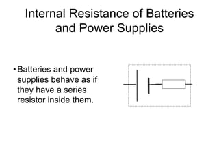
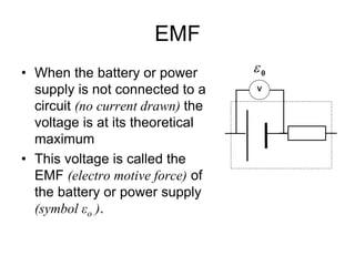
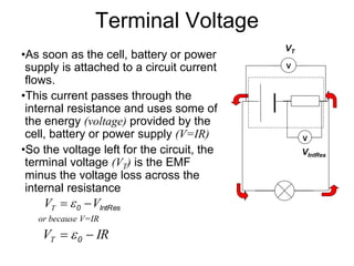
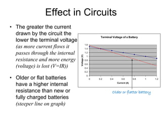
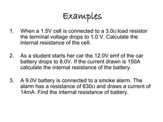
Internal 
Resistance 
The hidden resistance of cells, 
batteries and power supplies
What would happen if a low resistance copper wire 
is connected across the terminal of a 1.5V torch 
• Theoretically using 
V=IR 
V 
– if R is small (as it would 
be in a short thick wire) 
the current should be 
large, really large if R 
is very small 
battery? 
R 
I 
Lets try some figures 
• For such a short and thick piece of copper 
wire a resistance of 0.01 is not 
unreasonable 
• The battery has a voltage of 1.5 V 
so theoretically; 
1.5 
0.01 
V 
I   
R 
 150A 
• This is serious amount of current the amount 
needed to start your car 
• Enough to heat the wire red hot and melt it 
• That’s not what’s happening WHY??
What’s wrong and why? 
• Must be the calculation 
1.5 
0.01 
V 
I   
R 
150A  
• Either the value for V or R must be wrong, 
how could we check? 
– Measure R with a multimeter 
– Measure V with a voltmeter
so; 
• The battery has 1.5 V printed on it so let’s 
measure R (R=0.001) 
– That’s even worse and would make I 1500A ( ) 
• So what about the voltage of the battery? 
1.5 
0.001 
I  
– When its connected to the wire the voltage dropped 
– Why??
Internal Resistance of Batteries 
and Power Supplies 
• Batteries and power 
supplies behave as if 
they have a series 
resistor inside them.
EMF 
• When the battery or power 
supply is not connected to a 
circuit (no current drawn) the 
voltage is at its theoretical 
maximum 
• This voltage is called the 
EMF (electro motive force) of 
the battery or power supply 
(symbol εo ). 
0  
V
Terminal Voltage 
•As soon as the cell, battery or power 
supply is attached to a circuit current 
flows. 
•This current passes through the 
internal resistance and uses some of 
the energy (voltage) provided by the 
cell, battery or power supply (V=IR) 
•So the voltage left for the circuit, the 
terminal voltage (VT) is the EMF 
minus the voltage loss across the 
internal resistance 
0 IntRes V V T   
or because V=IR 
V IR T   0  
V 
VT 
V 
VIntRes
Effect in Circuits 
• The greater the current 
drawn by the circuit the 
lower the terminal voltage 
(as more current flows it 
passes through the internal 
resistance and more energy 
(voltage) is lost (V=IR)) 
• Older or flat batteries 
have a higher internal 
resistance than new or 
fully charged batteries 
(steeper line on graph) 
Terminal Voltage of a Battery 
1.6 
1.4 
1.2 
1 
0.8 
0.6 
0.4 
0.2 
0 
0 0.2 0.4 0.6 0.8 1 1.2 
Current (A) 
Voltage (V) 
Older or flatter battery
Examples 
1. When a 1.5V cell is connected to a 3.0Ω load resistor 
the terminal voltage drops to 1.0 V. Calculate the 
internal resistance of the cell. 
1.5Ω 
2. As a student starts her car the 12.0V emf of the car 
battery drops to 8.0V. If the current drawn is 150A 
calculate the internal resistance of the battery. 
0.027Ω 
3. A 9.0V battery is connected to a smoke alarm. The 
alarm has a resistance of 630Ω and draws a current of 
14mA. Find the internal resistance of battery. 
13Ω
Concept Questions 
• When a car has a flat battery why wont it start the car? 
• What measurable differences are there between a flat 
and fully charged battery? 
• Dry cells and batteries have a relatively high internal 
resistance. Explain why they are of limited use for low 
resistance circuits that require a terminal voltage close to 
the emf? 
• What happens to the terminal voltage of a cell as it goes 
flat 
• What happens to the emf of a cell as it goes flat? 
• How would you test a battery to see if it is flat?
Examples 
• ESA, Activity 13B, Pg 210 
• ABA Pg 136-138
Assignment
• That's an excellent question! Measuring internal resistance is a little more complicated. In general, the internal 
resistance of a battery is not a fixed value. It varies over time as the battery loses energy and also varies 
depending on the load, or how much current is drawn from the battery. Engineers refer to this as a non-linear 
resistance. You might also find that if really load down a battery, the internal resistance changes dramatically. In 
order to fully characterize the internal resistance, we need to take measurements over time and for different loads. 
The result is a set of graphs, each plotting values of resistance as a function of load current. This can be an 
involved process, depending on how much data you want. We can, however, get an estimate of the internal 
resistance by taking only two measurements with a voltmeter. First, we need to measure the "open circuit" voltage 
of the battery. This is simply the voltage at the battery terminals when no current is being drawn. Practically, it's 
hard to measure voltage without drawing some current, but most voltmeters have a high enough input resistance 
that it can be neglected. So we first measure the open circuit voltage, Vo. Let's say it's 0.9 volts, as in your case. 
Now we need to load down the battery and measure the voltage at the battery terminals again, let's call that Vl. 
Let's call the load resistance Rl. Given all those values, the equation for the internal resistance (Ri) of the battery 
is: Equ 1: Ri = Rl * ((Vo/Vl) - 1) You can derive this equation from the equation for a voltage divider: Equ 2: Vl = Vo 
* Rl / (Ri + Rl) This equation can be derived from application of Ohm law and Kirchoffs law. You can find that 
information from any text on electric circuit theory. Now we need to choose a value of Rl that gives us good 
numbers. From inspection of equ 2, we can observe that if Rl equals Ri, the load voltage will be exactly half of the 
open circuit voltage. This trick is commonly used if you have a variable resistor within the range of internal 
resistance. This is not always possible, so you might have to use several fixed resistors of different values. You 
will probably find that typical alkaline cells tend to have relatively low internal resistances when they are new. It's 
probably in the range of an ohm or so. You will probably need a resistor that is not more than 10 times that value 
to make good measurements. If you can find a 10 ohm resistor that's OK. Of course, you should start with higher 
values to see the effects. Start with 100 Ohms and see what you get. Then try lower values and run the 
calculations again. You can enter your values into a spreadsheet and plot the results. A word of caution: be careful 
when using low value resistors with good batteries, the current draw will be high enough the heat up the resistor 
(and the battery!).

Internal resistance

  • 1.
    Internal Resistance Thehidden resistance of cells, batteries and power supplies
  • 2.
    What would happenif a low resistance copper wire is connected across the terminal of a 1.5V torch • Theoretically using V=IR V – if R is small (as it would be in a short thick wire) the current should be large, really large if R is very small battery? R I 
  • 3.
    Lets try somefigures • For such a short and thick piece of copper wire a resistance of 0.01 is not unreasonable • The battery has a voltage of 1.5 V so theoretically; 1.5 0.01 V I   R  150A • This is serious amount of current the amount needed to start your car • Enough to heat the wire red hot and melt it • That’s not what’s happening WHY??
  • 4.
    What’s wrong andwhy? • Must be the calculation 1.5 0.01 V I   R 150A  • Either the value for V or R must be wrong, how could we check? – Measure R with a multimeter – Measure V with a voltmeter
  • 5.
    so; • Thebattery has 1.5 V printed on it so let’s measure R (R=0.001) – That’s even worse and would make I 1500A ( ) • So what about the voltage of the battery? 1.5 0.001 I  – When its connected to the wire the voltage dropped – Why??
  • 6.
    Internal Resistance ofBatteries and Power Supplies • Batteries and power supplies behave as if they have a series resistor inside them.
  • 7.
    EMF • Whenthe battery or power supply is not connected to a circuit (no current drawn) the voltage is at its theoretical maximum • This voltage is called the EMF (electro motive force) of the battery or power supply (symbol εo ). 0  V
  • 8.
    Terminal Voltage •Assoon as the cell, battery or power supply is attached to a circuit current flows. •This current passes through the internal resistance and uses some of the energy (voltage) provided by the cell, battery or power supply (V=IR) •So the voltage left for the circuit, the terminal voltage (VT) is the EMF minus the voltage loss across the internal resistance 0 IntRes V V T   or because V=IR V IR T   0  V VT V VIntRes
  • 9.
    Effect in Circuits • The greater the current drawn by the circuit the lower the terminal voltage (as more current flows it passes through the internal resistance and more energy (voltage) is lost (V=IR)) • Older or flat batteries have a higher internal resistance than new or fully charged batteries (steeper line on graph) Terminal Voltage of a Battery 1.6 1.4 1.2 1 0.8 0.6 0.4 0.2 0 0 0.2 0.4 0.6 0.8 1 1.2 Current (A) Voltage (V) Older or flatter battery
  • 10.
    Examples 1. Whena 1.5V cell is connected to a 3.0Ω load resistor the terminal voltage drops to 1.0 V. Calculate the internal resistance of the cell. 1.5Ω 2. As a student starts her car the 12.0V emf of the car battery drops to 8.0V. If the current drawn is 150A calculate the internal resistance of the battery. 0.027Ω 3. A 9.0V battery is connected to a smoke alarm. The alarm has a resistance of 630Ω and draws a current of 14mA. Find the internal resistance of battery. 13Ω
  • 11.
    Concept Questions •When a car has a flat battery why wont it start the car? • What measurable differences are there between a flat and fully charged battery? • Dry cells and batteries have a relatively high internal resistance. Explain why they are of limited use for low resistance circuits that require a terminal voltage close to the emf? • What happens to the terminal voltage of a cell as it goes flat • What happens to the emf of a cell as it goes flat? • How would you test a battery to see if it is flat?
  • 12.
    Examples • ESA,Activity 13B, Pg 210 • ABA Pg 136-138
  • 13.
  • 14.
    • That's anexcellent question! Measuring internal resistance is a little more complicated. In general, the internal resistance of a battery is not a fixed value. It varies over time as the battery loses energy and also varies depending on the load, or how much current is drawn from the battery. Engineers refer to this as a non-linear resistance. You might also find that if really load down a battery, the internal resistance changes dramatically. In order to fully characterize the internal resistance, we need to take measurements over time and for different loads. The result is a set of graphs, each plotting values of resistance as a function of load current. This can be an involved process, depending on how much data you want. We can, however, get an estimate of the internal resistance by taking only two measurements with a voltmeter. First, we need to measure the "open circuit" voltage of the battery. This is simply the voltage at the battery terminals when no current is being drawn. Practically, it's hard to measure voltage without drawing some current, but most voltmeters have a high enough input resistance that it can be neglected. So we first measure the open circuit voltage, Vo. Let's say it's 0.9 volts, as in your case. Now we need to load down the battery and measure the voltage at the battery terminals again, let's call that Vl. Let's call the load resistance Rl. Given all those values, the equation for the internal resistance (Ri) of the battery is: Equ 1: Ri = Rl * ((Vo/Vl) - 1) You can derive this equation from the equation for a voltage divider: Equ 2: Vl = Vo * Rl / (Ri + Rl) This equation can be derived from application of Ohm law and Kirchoffs law. You can find that information from any text on electric circuit theory. Now we need to choose a value of Rl that gives us good numbers. From inspection of equ 2, we can observe that if Rl equals Ri, the load voltage will be exactly half of the open circuit voltage. This trick is commonly used if you have a variable resistor within the range of internal resistance. This is not always possible, so you might have to use several fixed resistors of different values. You will probably find that typical alkaline cells tend to have relatively low internal resistances when they are new. It's probably in the range of an ohm or so. You will probably need a resistor that is not more than 10 times that value to make good measurements. If you can find a 10 ohm resistor that's OK. Of course, you should start with higher values to see the effects. Start with 100 Ohms and see what you get. Then try lower values and run the calculations again. You can enter your values into a spreadsheet and plot the results. A word of caution: be careful when using low value resistors with good batteries, the current draw will be high enough the heat up the resistor (and the battery!).