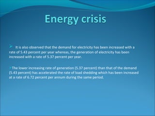
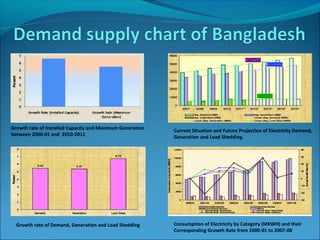
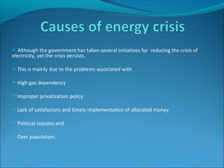
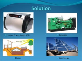
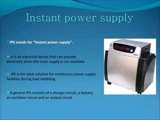
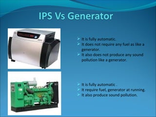
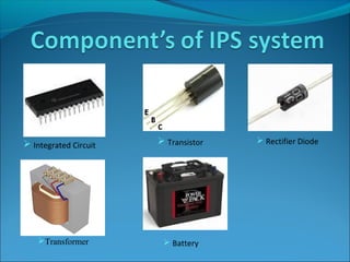
SUPERVISED BY
MARZIA HOQUE
DEPARTMENT OF EEE
 It is also observed that the demand for electricity has been increased with a
rate of 5.43 percent per year whereas, the generation of electricity has been
increased with a rate of 5.37 percent per year.
The lower increasing rate of generation (5.37 percent) than that of the demand
(5.43 percent) has accelerated the rate of load shedding which has been increased
at a rate of 6.72 percent per annum during the same period.
Growth rate of Installed Capacity and Maximum Generation
between 2000-01 and 2010-2011
Current Situation and Future Projection of Electricity Demand,
Generation and Load Shedding.
Consumption of Electricity by Category (MKWH) and their
Corresponding Growth Rate from 2000-01 to 2007-08
Growth rate of Demand, Generation and Load Shedding
 Although the government has taken several initiatives for reducing the crisis of
electricity, yet the crisis persists.
 This is mainly due to the problems associated with
 High gas dependency
 Improper privatization policy
 Lack of satisfactory and timely implementation of allocated money
 Political reasons and
 Over population.
 Solar Energy Biogas
 Generator Instant Power Supply (IPS)
IPS stands for “Instant power supply”.
 It is an electrical device that can provide
electricity when the main supply is not available
 IPS is the ideal solution for continuous power supply
facilities during load shedding.
A general IPS consists of a charger circuit, a battery,
an oscillator circuit and an output circuit
 It is fully automatic.
 It does not require any fuel as like a
generator.
 It also does not produce any sound
pollution like a generator.
 It is fully automatic .
 It require fuel, generator at running.
 It also produce sound pollution.
Transformer  Battery
 Integrated Circuit  Transistor  Rectifier Diode
SerialSerial
numbernumber
SpecificationsSpecifications
11 Main voltageMain voltage 220 V, 50 Hz220 V, 50 Hz
22 Battery voltageBattery voltage 12V DC12V DC
33 TemperatureTemperature 0-70 Deg. F.0-70 Deg. F.
44 Output Voltage rangeOutput Voltage range 220V – 240V, 50Hz220V – 240V, 50Hz
55 PowerPower 200 watt200 watt
66 Back up timeBack up time Battery dependentBattery dependent
77 LoadLoad Tube light & fan.Tube light & fan.
 The simplified block diagram of designed IPS is
shown in Fig. .This Transformer is Step down is
voltage range
 Primary 220 V AC & secondary 12-0-12 V .The
220V AC supply is applied to the input (step down)
transformer.12-0-12 V AC from input transformer is
then enters in to the rectifier bridge which This
power convert that AC to DC.
 This Instant Power supply DC battery 12 voltage
converting to the AC amplification high voltage 230 V.
 This 12-20V DC is used to charge a 12V DC battery
through the charger circuit. 12V DC is supplied to the
oscillator circuit that converts it into 12V AC
 This 12V AC is then amplified and transmitted to
the output (step up) transformer. 220V AC supply is
achieved from the output transformer.
Input Transformer (Step-DownInput Transformer (Step-Down))
Primary (Input )Primary (Input ) 220V, 50 Hz220V, 50 Hz
Secondary (Out put)Secondary (Out put) 12-0-12 V, 50 Hz.12-0-12 V, 50 Hz.
The Charger CircuitThe Charger Circuit
InputInput 12V, 50 Hz.12V, 50 Hz.
OutputOutput 13.5V DC. (Approximately) The Battery13.5V DC. (Approximately) The Battery
InputInput 13.5V DC13.5V DC
OutputOutput 12V DC12V DC
OscillationOscillation
InputInput 12V DC.12V DC.
OutputOutput 5 V, 50 Hz5 V, 50 Hz
Output Transformer (Step-up)Output Transformer (Step-up)
Primary InputPrimary Input 12 - 0 - 12 V, 50 Hz.12 - 0 - 12 V, 50 Hz.
Secondary OutputSecondary Output 230V, 50 Hz230V, 50 Hz
Load priority means the load where is necessary to apply the power
immediately .
In this thesis we can try to develop one thing that in the period of the
power failing or load shading the IPS backup the power supply but not at
a time every room.
By the selection of us 1st time backup drawing room or kitchen room
and then other room.
To apply this process the IPS longevity would be higher than the
normal IPS which has not this load priority system.
After all we think this system to effective and acceptable to us.
 In this Thesis program, we can understand the contraction of IPS
and know how can it works. We also understand it’s various
components. We should take care in the period of making and using of
this project.
THANKS TO ALL

Instant Power Supply ( IPS) System with Load Priority

  • 1.
  • 2.
     It isalso observed that the demand for electricity has been increased with a rate of 5.43 percent per year whereas, the generation of electricity has been increased with a rate of 5.37 percent per year. The lower increasing rate of generation (5.37 percent) than that of the demand (5.43 percent) has accelerated the rate of load shedding which has been increased at a rate of 6.72 percent per annum during the same period.
  • 3.
    Growth rate ofInstalled Capacity and Maximum Generation between 2000-01 and 2010-2011 Current Situation and Future Projection of Electricity Demand, Generation and Load Shedding. Consumption of Electricity by Category (MKWH) and their Corresponding Growth Rate from 2000-01 to 2007-08 Growth rate of Demand, Generation and Load Shedding
  • 4.
     Although thegovernment has taken several initiatives for reducing the crisis of electricity, yet the crisis persists.  This is mainly due to the problems associated with  High gas dependency  Improper privatization policy  Lack of satisfactory and timely implementation of allocated money  Political reasons and  Over population.
  • 5.
     Solar EnergyBiogas  Generator Instant Power Supply (IPS)
  • 6.
    IPS stands for“Instant power supply”.  It is an electrical device that can provide electricity when the main supply is not available  IPS is the ideal solution for continuous power supply facilities during load shedding. A general IPS consists of a charger circuit, a battery, an oscillator circuit and an output circuit
  • 7.
     It isfully automatic.  It does not require any fuel as like a generator.  It also does not produce any sound pollution like a generator.  It is fully automatic .  It require fuel, generator at running.  It also produce sound pollution.
  • 8.
    Transformer  Battery Integrated Circuit  Transistor  Rectifier Diode
  • 9.
    SerialSerial numbernumber SpecificationsSpecifications 11 Main voltageMainvoltage 220 V, 50 Hz220 V, 50 Hz 22 Battery voltageBattery voltage 12V DC12V DC 33 TemperatureTemperature 0-70 Deg. F.0-70 Deg. F. 44 Output Voltage rangeOutput Voltage range 220V – 240V, 50Hz220V – 240V, 50Hz 55 PowerPower 200 watt200 watt 66 Back up timeBack up time Battery dependentBattery dependent 77 LoadLoad Tube light & fan.Tube light & fan.
  • 12.
     The simplifiedblock diagram of designed IPS is shown in Fig. .This Transformer is Step down is voltage range  Primary 220 V AC & secondary 12-0-12 V .The 220V AC supply is applied to the input (step down) transformer.12-0-12 V AC from input transformer is then enters in to the rectifier bridge which This power convert that AC to DC.  This Instant Power supply DC battery 12 voltage converting to the AC amplification high voltage 230 V.  This 12-20V DC is used to charge a 12V DC battery through the charger circuit. 12V DC is supplied to the oscillator circuit that converts it into 12V AC  This 12V AC is then amplified and transmitted to the output (step up) transformer. 220V AC supply is achieved from the output transformer.
  • 13.
    Input Transformer (Step-DownInputTransformer (Step-Down)) Primary (Input )Primary (Input ) 220V, 50 Hz220V, 50 Hz Secondary (Out put)Secondary (Out put) 12-0-12 V, 50 Hz.12-0-12 V, 50 Hz. The Charger CircuitThe Charger Circuit InputInput 12V, 50 Hz.12V, 50 Hz. OutputOutput 13.5V DC. (Approximately) The Battery13.5V DC. (Approximately) The Battery InputInput 13.5V DC13.5V DC OutputOutput 12V DC12V DC OscillationOscillation InputInput 12V DC.12V DC. OutputOutput 5 V, 50 Hz5 V, 50 Hz Output Transformer (Step-up)Output Transformer (Step-up) Primary InputPrimary Input 12 - 0 - 12 V, 50 Hz.12 - 0 - 12 V, 50 Hz. Secondary OutputSecondary Output 230V, 50 Hz230V, 50 Hz
  • 14.
    Load priority meansthe load where is necessary to apply the power immediately . In this thesis we can try to develop one thing that in the period of the power failing or load shading the IPS backup the power supply but not at a time every room. By the selection of us 1st time backup drawing room or kitchen room and then other room. To apply this process the IPS longevity would be higher than the normal IPS which has not this load priority system. After all we think this system to effective and acceptable to us.
  • 15.
     In thisThesis program, we can understand the contraction of IPS and know how can it works. We also understand it’s various components. We should take care in the period of making and using of this project.
  • 16.