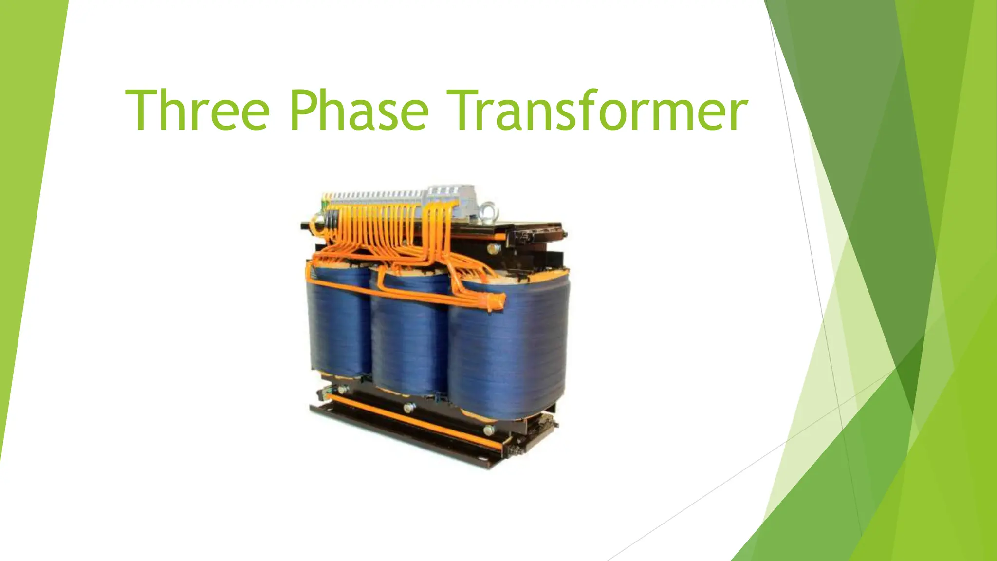
Three Phase Transformer
Definition:-
 Three-phase transformers are passive machines that pass electrical energy between
circuits. In the secondary circuit, a magnetic flux induces an electromotive force (emf),
thus stepping up (increase) or stepping down (decrease) voltages without altering the
frequency.
 In the core type construction of 3-phase transformer, the magnetic core is built up of
laminated steel sheets. The core consists of three limbs in the same plane and each
limb carries both low voltage (lv) winding and high-voltage (hv) winding.
 Used primarily in industrial facilities to provide power for three-phase motor loads, and
in utility power distribution applications. Nominal service voltages of 240, 400, 480,
600, and higher are typical.
Purpose of Using Three Phase Transformer:-
 The electric grid uses a three- phase power distribution system because it allows for
higher transmission at lower amperage .This makes it possible to use higher gauge
copper wire, significantly reducing both material and labour costs.
 The three-phase system is used to generate, transmit, and distribute electrical power
 It generates power on a large scale to meet the needs of industries and commercial
establishments
 Three identical single-phase transformers are connected suitably or combined on a
single core to form a three-phase system.
Construction:-
 A three phase transformer can be constructed by using common magnetic core for
both primary and secondary windings. As in case of single phase transformers ,
construction can be core type or shell type
 Similar to the single-phase transformer the core of the three-phase transformer is
constructed either in core type or shell type. The LV and HV windings of the 3-phases
are placed on the three limbs of the core.
 The construction of transformer is of iron core laminated with
steel bands. Core laminations are constructed from insulated
metal thin metal strips. These laminations are separated and
wound around the limb using a sheet of coat or parchment. The
winding consists of two types, main and secondary winding
 The Three Phase Transformer is advantageous in terms of cost,
and they offer effective operating conditions. The modern-day
scenario of the power system is significantly tilted toward the
three-phase systems in every stage of its operation that is the
generation, transmission, distribution, and the lion’s share of the
load in the form of industries. So, in every stage of these
operations, the three-phase transformer has a crucial role to
play, hence it must be adapted to these changes.
Types of Construction:-
There are two types of construction of 3 phase Transformer. They are-
1.Core Type
2. Shell Type
Core Type:-
The core of the three phase transformer is usually made up of three limbs in the same
plane. This can be built using stack lamination. The each leg of this core carries low
voltage and high voltage winding. The low voltage windings are insulated from the
core than the high voltage windings.
Shell Type:-
In a phase type three phase transformer, three phases are more independent than they
are in core type. Each phase has its individual magnetic circuit.
Working Principle:-
 The basic working principle of a three-phase transformer is the same as a single-phase
transformer i.e., on mutual induction. The alternating supply is given to the primary
windings and it induces an emf in the secondary winding. The amount of induced emf
depends upon the number of secondary turns (either can be a step-up or a step-down
transformer).
 Consider a three phase transformer in which the primary is connected to three
phase AC supply.
 When the primary is excited with the three phase supply source, three currents are
started flowing through individual phase windings. These currents produce the
magnetic fluxes in the respective cores. In three phase-system, at any instant the
sum of all the fluxes is same. These fluxes induce the secondary EMFS in respective
phase such that they maintain their phase angle between them. These EMFS drives
the currents in the secondary and hence to the load. Depends on the type of
connection used and number of turns on each phase, the voltage induced will be
varied for obtaining step-up or step-down of voltages
 These fluxes induce the secondary EMFS in respective phase such that they maintain
their phase angle between them. These EMFs drives the currents in the secondary
and hence to the load. Depends on the type of connection used and number of turns
on each phase, the voltage induced will be varied for obtaining step-up or step-
down of voltages.
Connections of Three Phase Transformer:-
The primary and secondary windings are connected in different ways, such as in delta
or star or combination of these two. The voltage and current ratings of the three phase
transformer is depends on suitable connection. The most commonly used connections
are-
1.Star-delta
2.Delta-star
3.Delta-delta
4.Star-star
Star-Delta Connection:
This type of connection is commonly used to step-down the voltages to a lower value
in transmission end substations. Utility companies use this connection to reduce the
voltage levels for distribution systems.
In this, the primary winding of the transformer is connected in star and secondary in
delta connection.
Delta-Star Connection:-
 This connection is used to step-up the voltage level and is commonly employed in
sending end or starting of high tension transmission system.
 In this connection, the primary is connected in delta fashion and secondary in star
fashion so that three phase 4 wire system at secondary is possible.
Delta-Delta Connection:-
This type of connection is used when the supply source is delta connected and the
secondary load. needs single voltage with high current. This is generally employed for
three phase power loads (like three phase motor).
In this, both primary and secondary windings are connected in delta fashion.
Star-Star Connection:-
In this, both primary and secondary windings are connected in star
fashion. Also there exist no phase difference between the primary and
secondary voltages.
Power Rating:
 In electrical engineering and mechanical engineering, the power rating of equipment
is the highest power input allowed to flow through particular equipment. According to
the particular discipline, the term power may refer to electrical or mechanical power.
 The copper and iron are the two types of losses that occur in the transformer. The
copper loss depends on the current (ampere) flows through the windings of the
transformer while the iron loss depends on the voltage (volts). i.e., the rating of the
transformer is in kVA.
 kVA stands for Kilovolt-Ampere and is the rating normally used to rate a transformer.
The size of a transformer is determined by the kVA of the load. In many circumstances
the power required by the load is equivalent to the rating of the transformer expressed
in either VA or kVA.
Losses in Transformer:
The losses of transformers are-
1.Iron Losses or Core Losses
2.Copper Losses
3.Eddy Current Losses
4.Hysteresis Losses
Iron Losses:
Iron loss in transformers is the combination of hysteresis loss (Ph) and eddy current loss
(Pe). This type of loss mainly occurs in the magnetic core of the transformer, and
depends on magnetic properties of core material.
Copper Losses:
Copper loss is due to ohmic resistance of the transformer windings. Copper loss for the primary winding is
I1
2R1 and for secondary winding is I2
2R2. Where, I1 and I2 are current in primary and secondary winding
respectively, R1 and R2 are the resistances of primary and secondary winding respectively. It is clear that Cu
loss is proportional to square of the current, and current depends on the load. Hence copper loss in
transformer varies with the load.
Hysteresis Losses:
Hysteresis loss is due to reversal of magnetization in the transformer core. This loss depends upon the
volume and grade of the iron, frequency of magnetic reversals and value of flux density. It can be given by,
Steinmetz formula:
Wh= ηBmax
1.6fV (watts)
where, η = Steinmetz hysteresis constant
V = volume of the core in m3
Eddy Current Losses:
In transformer, AC current is supplied to the primary winding which sets up alternating
magnetizing flux. When this flux links with secondary winding, it produces induced emf in it.
But some part of this flux also gets linked with other conducting parts like steel core or iron
body or the transformer, which will result in induced emf in those parts, causing small
circulating current in them. This current is called as eddy current. Due to these eddy currents,
some energy will be dissipated in the form of heat.
Efficiency:-
The transformer shows an efficiency of between 88 % and 99,5 % when operated between 60 %
and 90 % of the rated load.
Why efficiency of transformer is high?
 As transformer operates on the magnetizing phenomenon and it has no rotating parts, its
efficiency is very high. It usually stays above 95% but as the power flow across a transformer
is very high even small changes in terms of efficiency percentage gives significant energy
savings.
Advantages of Three Phase Transformer:-
• Less costly
• Lesser weight
• Less in size
• Less time required to assembling
• Require less space
• Deliver more power
• Higher efficiency
• Easier to install
• Easy transportation and installation
• Easy to repair
• Easy assembling
• The cost of a three phase transformer is lesser than the three single phase transformers having the same rating.
• Finally, it is easy to obtain a single phase power supply from a three phase supply, while it is not possible to get a
three phase power supply from a single phase power supply. Same is the case for single phase and three phase
transformers.
Disadvantages of Three Phase Transformer:-
• Higher cost of standby units.
• More costly and repairing inconveniences.
• In case of fault or failure of a three phase transformer, the power supply shutdowns in
the whole connected load areas. Hence, the definite and immediate power restoration
is not possible.
• A three phase transformer can’t be operated temporarily in open delta connection,
while it is possible in three single phase units transformer (in case of fault at single
unit).
• The whole unit needed to be replaced in case of failure, while in case of single phase
transformers, only the fault ones should be replaced with a new one.
• In case of failure of one single phase transformer (where three single phase
transformers are used instead of a single three phase transformer), the remaining two
single phase transformers still supply the power to the load points, while it is not
possible in case of failure of a three phase transformer.
Applications of Three Phase Transformer:-
1. Three-phase transformers are used for power generation
2. Used in electrical distribution network applications
3. They can be found in high power industrial loads such as rectifiers, motor
drives, and other equipment.
4. The three-phase transformer products are also widely used in industrial
and mining enterprises.
5. It is also suitable for low voltage distribution with low voltage and wide
fluctuation
The application range of three-phase transformer is wide, because it
has a high degree of isolation, high suppression of common-mode
interference, good N-G performance, and customized design according to
the special needs of users. That is why its usage is so widespread.
Conclusion:-
Three-phase transformers are passive machines that pass electrical energy
between circuits. In the secondary circuit, a magnetic flux induces an
electromotive force (emf), thus stepping up (increase) or stepping down
(decrease) voltages without altering the frequency.
3-Phase Δ/Y transformers are arguably the most common voltage transformers
in use because they can eliminate Triplen Harmonics generated by secondary
loads from getting through to the primary input current.
Core-type transformers act as single-core, three-phase transformers where each phase is
magnetically coupled to each other.
Shell-type transformers act as three separate single-phase transformers since their magnetic
fields are independent of one another.
1909023_EEE291_Three Phase Transformer.pptx

1909023_EEE291_Three Phase Transformer.pptx

  • 1.
  • 2.
    Definition:-  Three-phase transformersare passive machines that pass electrical energy between circuits. In the secondary circuit, a magnetic flux induces an electromotive force (emf), thus stepping up (increase) or stepping down (decrease) voltages without altering the frequency.  In the core type construction of 3-phase transformer, the magnetic core is built up of laminated steel sheets. The core consists of three limbs in the same plane and each limb carries both low voltage (lv) winding and high-voltage (hv) winding.  Used primarily in industrial facilities to provide power for three-phase motor loads, and in utility power distribution applications. Nominal service voltages of 240, 400, 480, 600, and higher are typical.
  • 3.
    Purpose of UsingThree Phase Transformer:-  The electric grid uses a three- phase power distribution system because it allows for higher transmission at lower amperage .This makes it possible to use higher gauge copper wire, significantly reducing both material and labour costs.  The three-phase system is used to generate, transmit, and distribute electrical power  It generates power on a large scale to meet the needs of industries and commercial establishments  Three identical single-phase transformers are connected suitably or combined on a single core to form a three-phase system.
  • 4.
    Construction:-  A threephase transformer can be constructed by using common magnetic core for both primary and secondary windings. As in case of single phase transformers , construction can be core type or shell type  Similar to the single-phase transformer the core of the three-phase transformer is constructed either in core type or shell type. The LV and HV windings of the 3-phases are placed on the three limbs of the core.
  • 5.
     The constructionof transformer is of iron core laminated with steel bands. Core laminations are constructed from insulated metal thin metal strips. These laminations are separated and wound around the limb using a sheet of coat or parchment. The winding consists of two types, main and secondary winding  The Three Phase Transformer is advantageous in terms of cost, and they offer effective operating conditions. The modern-day scenario of the power system is significantly tilted toward the three-phase systems in every stage of its operation that is the generation, transmission, distribution, and the lion’s share of the load in the form of industries. So, in every stage of these operations, the three-phase transformer has a crucial role to play, hence it must be adapted to these changes.
  • 6.
    Types of Construction:- Thereare two types of construction of 3 phase Transformer. They are- 1.Core Type 2. Shell Type Core Type:- The core of the three phase transformer is usually made up of three limbs in the same plane. This can be built using stack lamination. The each leg of this core carries low voltage and high voltage winding. The low voltage windings are insulated from the core than the high voltage windings. Shell Type:- In a phase type three phase transformer, three phases are more independent than they are in core type. Each phase has its individual magnetic circuit.
  • 8.
    Working Principle:-  Thebasic working principle of a three-phase transformer is the same as a single-phase transformer i.e., on mutual induction. The alternating supply is given to the primary windings and it induces an emf in the secondary winding. The amount of induced emf depends upon the number of secondary turns (either can be a step-up or a step-down transformer).
  • 9.
     Consider athree phase transformer in which the primary is connected to three phase AC supply.  When the primary is excited with the three phase supply source, three currents are started flowing through individual phase windings. These currents produce the magnetic fluxes in the respective cores. In three phase-system, at any instant the sum of all the fluxes is same. These fluxes induce the secondary EMFS in respective phase such that they maintain their phase angle between them. These EMFS drives the currents in the secondary and hence to the load. Depends on the type of connection used and number of turns on each phase, the voltage induced will be varied for obtaining step-up or step-down of voltages  These fluxes induce the secondary EMFS in respective phase such that they maintain their phase angle between them. These EMFs drives the currents in the secondary and hence to the load. Depends on the type of connection used and number of turns on each phase, the voltage induced will be varied for obtaining step-up or step- down of voltages.
  • 10.
    Connections of ThreePhase Transformer:- The primary and secondary windings are connected in different ways, such as in delta or star or combination of these two. The voltage and current ratings of the three phase transformer is depends on suitable connection. The most commonly used connections are- 1.Star-delta 2.Delta-star 3.Delta-delta 4.Star-star
  • 11.
    Star-Delta Connection: This typeof connection is commonly used to step-down the voltages to a lower value in transmission end substations. Utility companies use this connection to reduce the voltage levels for distribution systems. In this, the primary winding of the transformer is connected in star and secondary in delta connection.
  • 12.
    Delta-Star Connection:-  Thisconnection is used to step-up the voltage level and is commonly employed in sending end or starting of high tension transmission system.  In this connection, the primary is connected in delta fashion and secondary in star fashion so that three phase 4 wire system at secondary is possible.
  • 13.
    Delta-Delta Connection:- This typeof connection is used when the supply source is delta connected and the secondary load. needs single voltage with high current. This is generally employed for three phase power loads (like three phase motor). In this, both primary and secondary windings are connected in delta fashion.
  • 14.
    Star-Star Connection:- In this,both primary and secondary windings are connected in star fashion. Also there exist no phase difference between the primary and secondary voltages.
  • 15.
    Power Rating:  Inelectrical engineering and mechanical engineering, the power rating of equipment is the highest power input allowed to flow through particular equipment. According to the particular discipline, the term power may refer to electrical or mechanical power.  The copper and iron are the two types of losses that occur in the transformer. The copper loss depends on the current (ampere) flows through the windings of the transformer while the iron loss depends on the voltage (volts). i.e., the rating of the transformer is in kVA.  kVA stands for Kilovolt-Ampere and is the rating normally used to rate a transformer. The size of a transformer is determined by the kVA of the load. In many circumstances the power required by the load is equivalent to the rating of the transformer expressed in either VA or kVA.
  • 19.
    Losses in Transformer: Thelosses of transformers are- 1.Iron Losses or Core Losses 2.Copper Losses 3.Eddy Current Losses 4.Hysteresis Losses Iron Losses: Iron loss in transformers is the combination of hysteresis loss (Ph) and eddy current loss (Pe). This type of loss mainly occurs in the magnetic core of the transformer, and depends on magnetic properties of core material. Copper Losses: Copper loss is due to ohmic resistance of the transformer windings. Copper loss for the primary winding is I1 2R1 and for secondary winding is I2 2R2. Where, I1 and I2 are current in primary and secondary winding respectively, R1 and R2 are the resistances of primary and secondary winding respectively. It is clear that Cu loss is proportional to square of the current, and current depends on the load. Hence copper loss in transformer varies with the load.
  • 20.
    Hysteresis Losses: Hysteresis lossis due to reversal of magnetization in the transformer core. This loss depends upon the volume and grade of the iron, frequency of magnetic reversals and value of flux density. It can be given by, Steinmetz formula: Wh= ηBmax 1.6fV (watts) where, η = Steinmetz hysteresis constant V = volume of the core in m3 Eddy Current Losses: In transformer, AC current is supplied to the primary winding which sets up alternating magnetizing flux. When this flux links with secondary winding, it produces induced emf in it. But some part of this flux also gets linked with other conducting parts like steel core or iron body or the transformer, which will result in induced emf in those parts, causing small circulating current in them. This current is called as eddy current. Due to these eddy currents, some energy will be dissipated in the form of heat.
  • 21.
    Efficiency:- The transformer showsan efficiency of between 88 % and 99,5 % when operated between 60 % and 90 % of the rated load. Why efficiency of transformer is high?  As transformer operates on the magnetizing phenomenon and it has no rotating parts, its efficiency is very high. It usually stays above 95% but as the power flow across a transformer is very high even small changes in terms of efficiency percentage gives significant energy savings.
  • 22.
    Advantages of ThreePhase Transformer:- • Less costly • Lesser weight • Less in size • Less time required to assembling • Require less space • Deliver more power • Higher efficiency • Easier to install • Easy transportation and installation • Easy to repair • Easy assembling • The cost of a three phase transformer is lesser than the three single phase transformers having the same rating. • Finally, it is easy to obtain a single phase power supply from a three phase supply, while it is not possible to get a three phase power supply from a single phase power supply. Same is the case for single phase and three phase transformers.
  • 23.
    Disadvantages of ThreePhase Transformer:- • Higher cost of standby units. • More costly and repairing inconveniences. • In case of fault or failure of a three phase transformer, the power supply shutdowns in the whole connected load areas. Hence, the definite and immediate power restoration is not possible. • A three phase transformer can’t be operated temporarily in open delta connection, while it is possible in three single phase units transformer (in case of fault at single unit). • The whole unit needed to be replaced in case of failure, while in case of single phase transformers, only the fault ones should be replaced with a new one. • In case of failure of one single phase transformer (where three single phase transformers are used instead of a single three phase transformer), the remaining two single phase transformers still supply the power to the load points, while it is not possible in case of failure of a three phase transformer.
  • 24.
    Applications of ThreePhase Transformer:- 1. Three-phase transformers are used for power generation 2. Used in electrical distribution network applications 3. They can be found in high power industrial loads such as rectifiers, motor drives, and other equipment. 4. The three-phase transformer products are also widely used in industrial and mining enterprises. 5. It is also suitable for low voltage distribution with low voltage and wide fluctuation The application range of three-phase transformer is wide, because it has a high degree of isolation, high suppression of common-mode interference, good N-G performance, and customized design according to the special needs of users. That is why its usage is so widespread.
  • 25.
    Conclusion:- Three-phase transformers arepassive machines that pass electrical energy between circuits. In the secondary circuit, a magnetic flux induces an electromotive force (emf), thus stepping up (increase) or stepping down (decrease) voltages without altering the frequency. 3-Phase Δ/Y transformers are arguably the most common voltage transformers in use because they can eliminate Triplen Harmonics generated by secondary loads from getting through to the primary input current. Core-type transformers act as single-core, three-phase transformers where each phase is magnetically coupled to each other. Shell-type transformers act as three separate single-phase transformers since their magnetic fields are independent of one another.