Download as PDF, PPTX

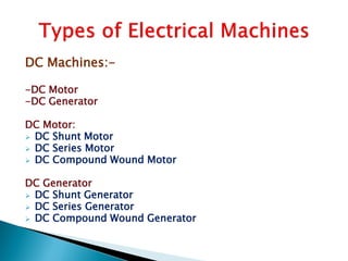
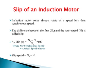
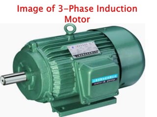
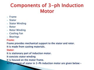
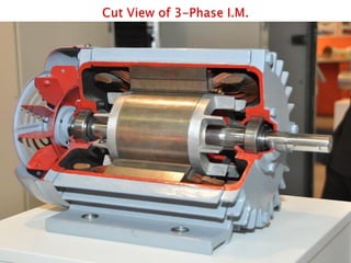
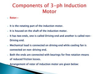

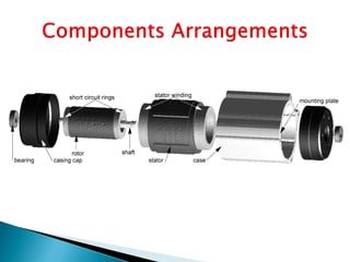
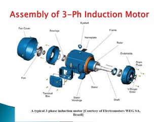
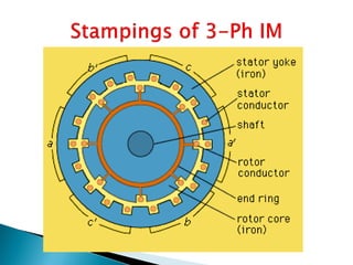
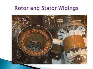
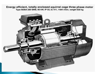
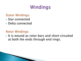
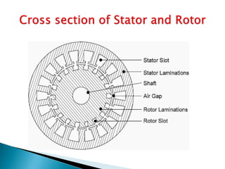
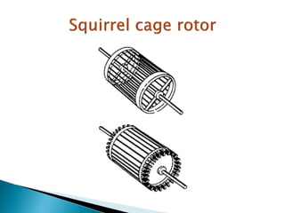
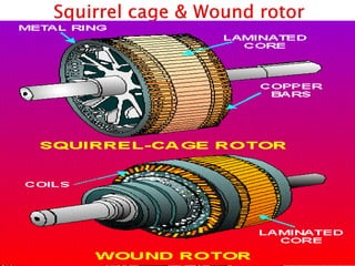

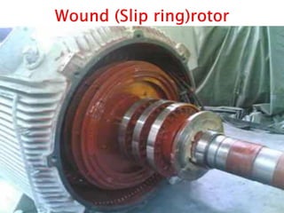
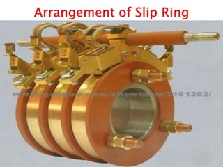
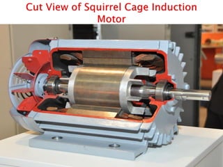
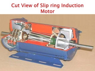
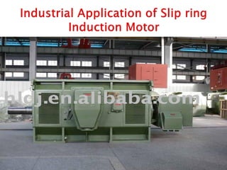
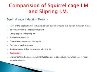
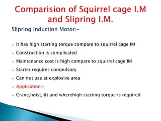


This document outlines and describes the key components and operating principles of three-phase induction motors, which are widely used in industrial applications due to their continuous operation. It discusses the main types of electrical machines and induction motors, including squirrel cage and slip ring induction motors. The document explains the basic working principle of three-phase induction motors, involving the generation of a rotating magnetic field in the stator that induces current in the rotor. It also describes the main components of three-phase induction motors such as the frame, stator, rotor, and windings.


