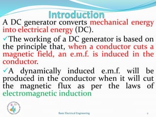
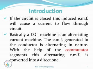
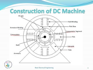
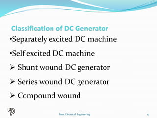
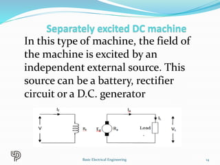
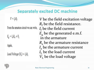
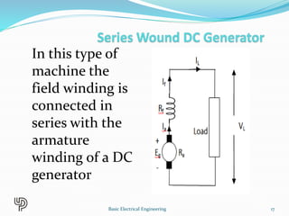
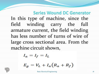
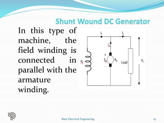
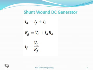
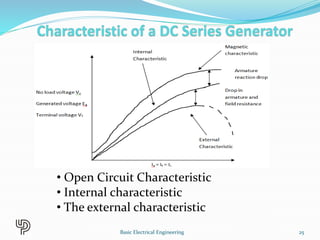
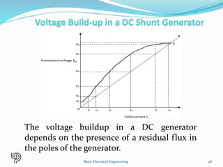
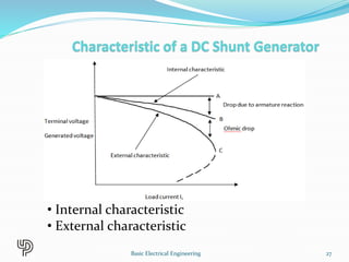
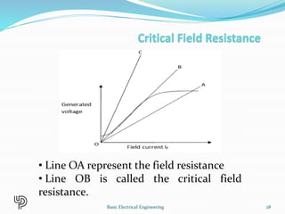
DC GENERATOR & DC
MOTORS
By
Dr. M. Ajay Kumar
Associate Professor, EEE.
1
Basic Electrical Engineering
A DC generator converts mechanical energy
into electrical energy (DC).
The working of a DC generator is based on
the principle that, when a conductor cuts a
magnetic field, an e.m.f. is induced in the
conductor.
A dynamically induced e.m.f. will be
produced in the conductor when it will cut
the magnetic flux as per the laws of
electromagnetic induction
2
Basic Electrical Engineering
 If the circuit is closed this induced e.m.f.
will cause a current to flow through
circuit.
 Basically a D.C. machine is an alternating
current machine. The e.m.f. generated in
the conductor is alternating in nature.
With the help of the commutator
segments this alternating e.m.f. is
converted into a direct one.
3
Basic Electrical Engineering
4
Basic Electrical Engineering
1. Pole
2.Armature
3.Yoke
4.Commutator
5.Brushes
6.Interpole
5
Basic Electrical Engineering
6
Basic Electrical Engineering
7
Basic Electrical Engineering
There are two types of windings
Lap winding
• A = P
• The armature
windings are
divided into
no. of sections
equal to the no
of poles
Wave winding
• A = 2
• Used in high
voltage low
current output.
• Requires 2
brushes
8
Basic Electrical Engineering
9
Basic Electrical Engineering
10
Basic Electrical Engineering
Let, Ø= flux per pole in weber
Z = Total number of conductor
P = Number of poles
A = Number of parallel paths
N =armature speed in rpm
Eg = emf generated in any on of the
parallel path
11
Basic Electrical Engineering
Flux cut by 1 conductor
in 1 revolution = P * φ
Flux cut by 1 conductor in
60 sec = P φ N /60
Avg emf generated in 1
conductor = PφN/60
Number of conductors in
each parallel path = Z /A
Eg = PφNZ/60A
12
Basic Electrical Engineering
•Separately excited DC machine
•Self excited DC machine
 Shunt wound DC generator
 Series wound DC generator
 Compound wound
13
Basic Electrical Engineering
In this type of machine, the field of
the machine is excited by an
independent external source. This
source can be a battery, rectifier
circuit or a D.C. generator
14
Basic Electrical Engineering
Basic Electrical Engineering 15
V be the field excitation voltage
Rf be the field resistance.
If be the field current
Eg be the generated e.m.f.
in the armature
Ra be the armature resistance
Ia be the armature current
IL be the load current
VL be the load voltage
16
Basic Electrical Engineering
In this type of
machine the
field winding is
connected in
series with the
armature
winding of a DC
generator
17
Basic Electrical Engineering
In this type of machine, since the
field winding carry the full
armature current, the field winding
has less number of turns of wire of
large cross sectional area. From the
machine circuit shown,
18
Basic Electrical Engineering
In this type of
machine, the
field winding is
connected in
parallel with the
armature
winding.
19
Basic Electrical Engineering
20
Basic Electrical Engineering
In this type of DC machine the poles
are having two separate windings.
That is for a compound wound DC
machine there are two field windings,
namely, the shunt field winding and
the series field winding.
21
Basic Electrical Engineering
Depending upon how these two
windings are connected with the
armature of the DC machine, they are
classified as,
•Long shunt compound DC machine.
•Short shunt compound DC machine.
22
Basic Electrical Engineering
Long shunt Short shunt
23
Basic Electrical Engineering
This characteristic is called the
magnetic characteristic or the Open
Circuit Characteristic (O.C.C.) of a
separately excited D.C. generator.
24
Basic Electrical Engineering
• Open Circuit Characteristic
• Internal characteristic
• The external characteristic
25
Basic Electrical Engineering
The voltage buildup in a DC generator
depends on the presence of a residual flux in
the poles of the generator.
26
Basic Electrical Engineering
• Internal characteristic
• External characteristic
27
Basic Electrical Engineering
• Line OA represent the field resistance
• Line OB is called the critical field
resistance.
28
Basic Electrical Engineering
•DC shunt generator is used for such
applications where constant voltage is
required.
•DC series generators are used as Boosters
and also as a supply for arc lamps.
•Differential Compound generators are used
to supply dc welding machines.
•Level compound generators are used to
supply power for offices, hostels and Lodges
etc.
29
Basic Electrical Engineering
•Over compound generators are used to
compensate the voltage drop in Feeders.
• Separately excited generator are used
as a supply for DC Motors ,it is also used
for such applications where a wide range
of voltage is required for the testing
purposes.
30
Basic Electrical Engineering

DC Generator.ppt

  • 1.
    DC GENERATOR &DC MOTORS By Dr. M. Ajay Kumar Associate Professor, EEE. 1 Basic Electrical Engineering
  • 2.
    A DC generatorconverts mechanical energy into electrical energy (DC). The working of a DC generator is based on the principle that, when a conductor cuts a magnetic field, an e.m.f. is induced in the conductor. A dynamically induced e.m.f. will be produced in the conductor when it will cut the magnetic flux as per the laws of electromagnetic induction 2 Basic Electrical Engineering
  • 3.
     If thecircuit is closed this induced e.m.f. will cause a current to flow through circuit.  Basically a D.C. machine is an alternating current machine. The e.m.f. generated in the conductor is alternating in nature. With the help of the commutator segments this alternating e.m.f. is converted into a direct one. 3 Basic Electrical Engineering
  • 4.
  • 5.
  • 6.
  • 7.
  • 8.
    There are twotypes of windings Lap winding • A = P • The armature windings are divided into no. of sections equal to the no of poles Wave winding • A = 2 • Used in high voltage low current output. • Requires 2 brushes 8 Basic Electrical Engineering
  • 9.
  • 10.
  • 11.
    Let, Ø= fluxper pole in weber Z = Total number of conductor P = Number of poles A = Number of parallel paths N =armature speed in rpm Eg = emf generated in any on of the parallel path 11 Basic Electrical Engineering
  • 12.
    Flux cut by1 conductor in 1 revolution = P * φ Flux cut by 1 conductor in 60 sec = P φ N /60 Avg emf generated in 1 conductor = PφN/60 Number of conductors in each parallel path = Z /A Eg = PφNZ/60A 12 Basic Electrical Engineering
  • 13.
    •Separately excited DCmachine •Self excited DC machine  Shunt wound DC generator  Series wound DC generator  Compound wound 13 Basic Electrical Engineering
  • 14.
    In this typeof machine, the field of the machine is excited by an independent external source. This source can be a battery, rectifier circuit or a D.C. generator 14 Basic Electrical Engineering
  • 15.
  • 16.
    V be thefield excitation voltage Rf be the field resistance. If be the field current Eg be the generated e.m.f. in the armature Ra be the armature resistance Ia be the armature current IL be the load current VL be the load voltage 16 Basic Electrical Engineering
  • 17.
    In this typeof machine the field winding is connected in series with the armature winding of a DC generator 17 Basic Electrical Engineering
  • 18.
    In this typeof machine, since the field winding carry the full armature current, the field winding has less number of turns of wire of large cross sectional area. From the machine circuit shown, 18 Basic Electrical Engineering
  • 19.
    In this typeof machine, the field winding is connected in parallel with the armature winding. 19 Basic Electrical Engineering
  • 20.
  • 21.
    In this typeof DC machine the poles are having two separate windings. That is for a compound wound DC machine there are two field windings, namely, the shunt field winding and the series field winding. 21 Basic Electrical Engineering
  • 22.
    Depending upon howthese two windings are connected with the armature of the DC machine, they are classified as, •Long shunt compound DC machine. •Short shunt compound DC machine. 22 Basic Electrical Engineering
  • 23.
    Long shunt Shortshunt 23 Basic Electrical Engineering
  • 24.
    This characteristic iscalled the magnetic characteristic or the Open Circuit Characteristic (O.C.C.) of a separately excited D.C. generator. 24 Basic Electrical Engineering
  • 25.
    • Open CircuitCharacteristic • Internal characteristic • The external characteristic 25 Basic Electrical Engineering
  • 26.
    The voltage buildupin a DC generator depends on the presence of a residual flux in the poles of the generator. 26 Basic Electrical Engineering
  • 27.
    • Internal characteristic •External characteristic 27 Basic Electrical Engineering
  • 28.
    • Line OArepresent the field resistance • Line OB is called the critical field resistance. 28 Basic Electrical Engineering
  • 29.
    •DC shunt generatoris used for such applications where constant voltage is required. •DC series generators are used as Boosters and also as a supply for arc lamps. •Differential Compound generators are used to supply dc welding machines. •Level compound generators are used to supply power for offices, hostels and Lodges etc. 29 Basic Electrical Engineering
  • 30.
    •Over compound generatorsare used to compensate the voltage drop in Feeders. • Separately excited generator are used as a supply for DC Motors ,it is also used for such applications where a wide range of voltage is required for the testing purposes. 30 Basic Electrical Engineering