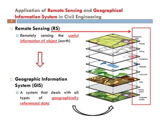
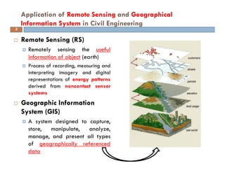
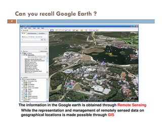
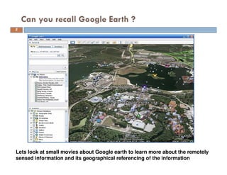
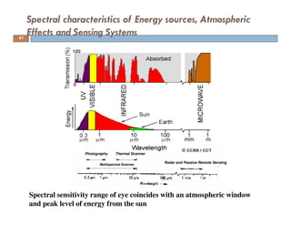
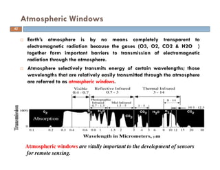
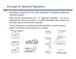
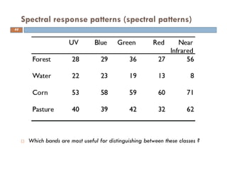
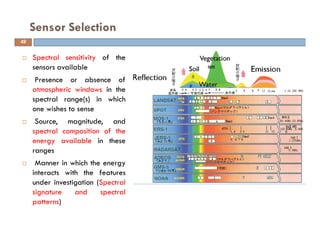
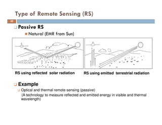
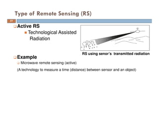
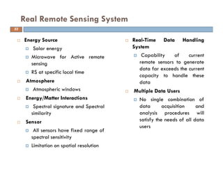
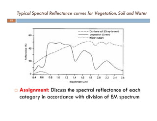
This document discusses the application of remote sensing and geographical information systems in civil engineering. It begins by defining remote sensing as the acquisition of information about an object without physical contact, typically by measuring electromagnetic radiation. It then defines geographical information systems as a system for capturing, storing, analyzing and presenting spatially referenced data. The document provides examples of how remote sensing data from sources like Google Earth can be spatially analyzed using a GIS. It proceeds to discuss key concepts in remote sensing including the electromagnetic spectrum, atmospheric interactions with radiation, and radiation measurement principles.
Spectral signatures are the specific combination of emitted, reflected or absorbed electromagnetic radiation (EM) at varying wavelengths which can uniquely identify an object. Here, i have focused on the spectral signature of water and the various micro-process that are responsible for it.
Basic Concepts, Explanation, and Application. Fundamental Remote Sensing; Advantage/ disadvantages, Imaging/non Imaging sensors, RAR and SAR, SAR Geometry, Resolutions in the microwave, Geometric Distortions in SAR, Polarization in SAR, Target Interaction, SAR Interferometry
Types of Platforms
1. Airbrone Platforms
2. Spacebrone Platforms
Platforms are Vital Role in remote sensing data acquisition
Necessary to correct the position the remote sensors that collect data from the objects of interest
This is all about remote sensing. Remote sensing is the acquisition of information about an object or phenomenon without making physical contact with the object and thus in contrast to on-site observation, especially the Earth.Remote sensing is the process of detecting and monitoring the physical characteristics of an area by measuring its reflected and emitted radiation at a distance from the targeted area. Special cameras collect remotely sensed imagesof the Earth, which help researchers "sense" things about the Earth.
Remote Sensing Data Acquisition,Scanning/Imaging systemsdaniyal rustam
full of concepts about RS data acquisition scanning and imaging systems. Best for students of remote sensing. in this presentation we briefly explained the concept of scanning in remote sensing.
Apresentação do professor Laerte Guimarães Ferreira, do Laboratório de Processamento de Imagens e Geoprocessamento (LAPIG) do Instituto de Estudos Sócio-Ambientais da Universidade Federal de Goiás (IESA/UFG). Palestra realizada durante a 2ª Rodada do Ciclo de Palestras do Núcleo de Inteligência Territorial (NIT) em 13 de dezembro de 2012.
Ambient Air Radon Monitoring Around Mosaic Riverview’S Phosphogypsum Board Pr...seanpmcginnis
Presentation to the Environmental Protection Commission of Hillsborough County Board on the initial findings of the air radon monitoring around the phosphogypsum stack located near Tampa, FL
A remote sensing system uses a detector to sense the reflected or emitted energy from the earth's surface, perhaps modified by the intervening atmosphere. The sensor can be on a satellite, aircraft, or drone. The sensor turns the energy into a voltage, which an analog to digital converter turns into a single integer value (called the Digital Number, or DN) for the energy. Alternatively a digital detector can store the DN directly. We can then display this value with an appropriate color to build up an image of the region sensed by the system. The DN represents the energy sensed by the sensor in a particular part of the electromagnetic spectrum, emitted or reflected from a particular region. The principles can also be applied to sonar imagery, especially useful in water where sound penetrates readily whereas electromagnetic energy attenuates rapidly.
Definitions,
Remote sensing systems can be active or passive: active systems put out their own source of energy (a large "flash bulb") whereas passive systems use solar energy reflected from the surface or thermal energy emitted by the surface. Active systems can achieve higher resolution.
Satellite resolution considers four things: spatial, spectral, radiometric, and temporal resolution.
Electromagnetic radiation and the atmosphere control many aspects of a remote sensing system.
Satellite orbits determine many characteristics of the imagery, what the satellite sees, and how often it revisits an area.
The signal to noise ratio is important for the design of remote sensing systems.
Satellite band tradeoffs.
Interpreting satellite reflectance patterns and images uses various statistical measures to assess surface properties in the image.
The colors used on the display are gray shading for single bands, and RGB for multi-band composites. We can also perform image merge and sharpening to combine the advantages of both panchromatic (higher spatial resolution) and color imagery (better differentiation of surface materials).
Keys for image analysis
Hyperspectral imagery
Spectral reflectance library--different materials reflect radiation differently
APPLICATION OF REMOTE SENSING AND GIS IN AGRICULTURELagnajeetRoy
India is a country that depends on agriculture. Today in this era of technological supremacy, agriculture is also using different new technologies like some robotic machinery to remote sensing and Geographical Information System (GIS) for the betterment of agriculture. It is easy to get the information about that area where human cannot check the condition everyday and help in gathering the data with the help of remote sensing. Whereas GIS helps in preparation of map that shows an accurate representation of data we get through remote sensing. From disease estimation to stress factor due to water, from ground water quality index to acreage estimation in various way agriculture is being profited by the application of remote sensing and GIS in agriculture. The applications of those software or techniques are very new to the agriculture domain still much more exploration is needed in this part. New software’s are developing in different parts of the world and remote sensing. Today farmers understand the beneficiaries of these kinds of techniques to the farm field which help in increasing productivity that will help future generation as technology is hype in traditional system of farming.
physics of remote sensing,ideal remote sensing,swath,platform,sensor,orbit and its characteristics,electromagnetic radiations,EMR solar radiations and its application,shortwave and long waves,spectrul reflectance curve, resolution AND multi concept,FCC,
The students can learn about basics of image processing using matlab.
It explains the image operations with the help of examples and Matlab codes.
Students can fine sample images and .m code from the link given in slides.
This lecture is about particle image velocimetry technique. It include discussion about the basic element of PIV setup, image capturing, laser lights, synchronize and correlation analysis.
Explore the innovative world of trenchless pipe repair with our comprehensive guide, "The Benefits and Techniques of Trenchless Pipe Repair." This document delves into the modern methods of repairing underground pipes without the need for extensive excavation, highlighting the numerous advantages and the latest techniques used in the industry.
Learn about the cost savings, reduced environmental impact, and minimal disruption associated with trenchless technology. Discover detailed explanations of popular techniques such as pipe bursting, cured-in-place pipe (CIPP) lining, and directional drilling. Understand how these methods can be applied to various types of infrastructure, from residential plumbing to large-scale municipal systems.
Ideal for homeowners, contractors, engineers, and anyone interested in modern plumbing solutions, this guide provides valuable insights into why trenchless pipe repair is becoming the preferred choice for pipe rehabilitation. Stay informed about the latest advancements and best practices in the field.
About
Indigenized remote control interface card suitable for MAFI system CCR equipment. Compatible for IDM8000 CCR. Backplane mounted serial and TCP/Ethernet communication module for CCR remote access. IDM 8000 CCR remote control on serial and TCP protocol.
• Remote control: Parallel or serial interface.
• Compatible with MAFI CCR system.
• Compatible with IDM8000 CCR.
• Compatible with Backplane mount serial communication.
• Compatible with commercial and Defence aviation CCR system.
• Remote control system for accessing CCR and allied system over serial or TCP.
• Indigenized local Support/presence in India.
• Easy in configuration using DIP switches.
Technical Specifications
Indigenized remote control interface card suitable for MAFI system CCR equipment. Compatible for IDM8000 CCR. Backplane mounted serial and TCP/Ethernet communication module for CCR remote access. IDM 8000 CCR remote control on serial and TCP protocol.
Key Features
Indigenized remote control interface card suitable for MAFI system CCR equipment. Compatible for IDM8000 CCR. Backplane mounted serial and TCP/Ethernet communication module for CCR remote access. IDM 8000 CCR remote control on serial and TCP protocol.
• Remote control: Parallel or serial interface
• Compatible with MAFI CCR system
• Copatiable with IDM8000 CCR
• Compatible with Backplane mount serial communication.
• Compatible with commercial and Defence aviation CCR system.
• Remote control system for accessing CCR and allied system over serial or TCP.
• Indigenized local Support/presence in India.
Application
• Remote control: Parallel or serial interface.
• Compatible with MAFI CCR system.
• Compatible with IDM8000 CCR.
• Compatible with Backplane mount serial communication.
• Compatible with commercial and Defence aviation CCR system.
• Remote control system for accessing CCR and allied system over serial or TCP.
• Indigenized local Support/presence in India.
• Easy in configuration using DIP switches.
Saudi Arabia stands as a titan in the global energy landscape, renowned for its abundant oil and gas resources. It's the largest exporter of petroleum and holds some of the world's most significant reserves. Let's delve into the top 10 oil and gas projects shaping Saudi Arabia's energy future in 2024.
Sachpazis:Terzaghi Bearing Capacity Estimation in simple terms with Calculati...Dr.Costas Sachpazis
Terzaghi's soil bearing capacity theory, developed by Karl Terzaghi, is a fundamental principle in geotechnical engineering used to determine the bearing capacity of shallow foundations. This theory provides a method to calculate the ultimate bearing capacity of soil, which is the maximum load per unit area that the soil can support without undergoing shear failure. The Calculation HTML Code included.
Overview of the fundamental roles in Hydropower generation and the components involved in wider Electrical Engineering.
This paper presents the design and construction of hydroelectric dams from the hydrologist’s survey of the valley before construction, all aspects and involved disciplines, fluid dynamics, structural engineering, generation and mains frequency regulation to the very transmission of power through the network in the United Kingdom.
Author: Robbie Edward Sayers
Collaborators and co editors: Charlie Sims and Connor Healey.
(C) 2024 Robbie E. Sayers
Remote sensing principles-spectral signature-spectural range
1. APPLICATION OF REMOTE SENSING AND
GEOGRAPHICAL INFORMATION SYSTEM IN
CIVIL ENGINEERING
Date:
INSTRUCTOR
DR. MOHSIN SIDDIQUE
ASSIST. PROFESSOR
DEPARTMENT OF CIVIL ENGINEERING
2. Remote Sensing (RS)
Remotely sensing the useful
information of object (earth)
Geographic Information
System (GIS)
A system that deals with all
types of geographically
referenced data
Application of Remote Sensing and Geographical
Information System in Civil Engineering
2
3. Remote Sensing (RS)
Remotely sensing the useful
information of object (earth)
Process of recording, measuring and
interpreting imagery and digital
representations of energy patterns
derived from noncontact sensor
systems
Geographic Information
System (GIS)
A system designed to capture,
store, manipulate, analyze,
manage, and present all types
of geographically referenced
data
Application of Remote Sensing and Geographical
Information System in Civil Engineering
3
4. Can you recall Google Earth ?
While the representation and management of remotely sensed data on
geographical locations is made possible through GIS
The information in the Google earth is obtained through Remote Sensing
4
5. Can you recall Google Earth ?
Lets look at small movies about Google earth to learn more about the remotely
sensed information and its geographical referencing of the information
5
6. Remote sensing has been variously defined but basically it is the art or science
of telling something about an object without touching it. (Fischer et al.,
1976, p. 34)
Remote sensing is the acquisition of physical data of an object without
touch or contact. (Lintz and Simonett, 1976, p. 1)
Remote sensing is the observation of a target by a device separated from it
by some distance. (Barrett and Curtis, 1976, p. 3)
The term “remote sensing” in its broadest sense merely means
“reconnaissance at a distance.” (Colwell, 1966, p. 71)
Remote sensing is the art, science and technology of obtaining reliable
information about physical objects and the environment, through the
process of recording, measuring and interpreting imagery and digital
representations of energy patterns derived from noncontact sensor systems
(Lecture Note by Wataru Takauchi, 2009)
Remote Sensing
6
7. Remote sensing is the science of deriving information about an object from
measurements made at a distance from the object, i.e., without actually
coming in contact with it. The quantity most frequently measured in present-
day remote sensing systems is the electromagnetic energy emanating from
objects of interest, and although there are other possibilities (e.g., seismic
waves, sonic waves, and gravitational force), our attention . . . is focused upon
systems which measure electromagnetic energy. (D. A. Landgrebe, quoted in
Swain and Davis, 1978, p. 1)
Remote sensing is the practice of deriving information about the Earth’s land and
water surfaces using images acquired from an overhead perspective, using
electromagnetic radiation in one or more regions of the electromagnetic
spectrum, reflected or emitted from the Earth’s surface. (James B.
Campbell, Randolph H. Wynne (2011): Introduction to Remote Sensing)
Remote Sensing
7
Is remote sensing limited to use of electromagnetic radiation ?
8. Various Steps in RS
8
(A) Energy Source
(B) Radiation and the Atmosphere
(C) Interaction with the Target
(D) Recording of Energy by the Sensor
(E) Transmission, Reception, and Processing
(F) Interpretation and Analysis
(G) Application
9. Source of Electromagnetic Radiation
9
Nuclear reactions within the Sun produce a full spectrum of
electromagnetic radiation, which is transmitted through space without
experiencing major changes.
As this radiation
approaches the Earth, it
passes through the
atmosphere before reaching
the Earth’s surface.
Some is reflected upward
from the Earth’s surface; it
is this radiation that forms
the basis for photographs
and similar images. Other
solar radiation is absorbed
at the surface of the Earth
and is then reradiated as
thermal energy.
10. Source of Electromagnetic Radiation
By recording emitted or reflected radiation and applying knowledge of its
behaviour as it passes through the Earth’s atmosphere and interacts with
objects, remote sensing analysts develop knowledge of the character of
features such as vegetation, structures, soils, rock, or water bodies on the
Earth’s surface.
10
Remote sensing of reflected radiation Remote sensing of emitted radiation
11. The electric and magnetic components are oriented at right angles to one
another and vary along an axis perpendicular to the axis of propagation
Magnetic field (H) oriented at right angles to the electrical field is
propagated in phase with the electrical field (E)
Electromagnetic Radiations (EMR)
λfc =
Electric (E) and magnetic
(H) components of EMR.
smc /103 8
×=
11
12. Two characteristics of electromagnetic radiation are particularly important for
understanding remote sensing. These are the wavelength and frequency.
Electromagnetic Radiations (EMR)
f
c
=λ
Wave length (λ) is the length of one wave
cycle, which can be measured as the
distance between successive wave crests.
Wavelength is measured in metres (m)
Frequency (f) refers to the number of
cycles of a wave passing a fixed point per
unit of time. Frequency is normally
measured in hertz (Hz), equivalent to one
cycle per second, and various multiples of
hertz
Remember ! Two are inversely related to each other. The shorter the
wavelength, the higher the frequency. The longer the wavelength, the
lower the frequency
12
14. Electromagnetic (EM) Spectrum
14
The most familiar form of EMR is visible light, which forms only a small (but
very important) portion of the full EM spectrum.
The large segments of this spectrum that lie outside the visible range require our
special attention because they may behave in ways that are quite foreign to our
everyday experience with visible radiation.
16. Two important categories are not shown in above Table. The optical spectrum,
from 0.30 to 15 µm, defines those wavelengths that can be reflected and
refracted with lenses and mirrors. The reflective spectrum extends from about
0.38 to 3.0 µm; it defines that portion of the solar spectrum used directly for
remote sensing.
Electromagnetic (EM) Spectrum
reflective
spectrum
Optical
spectrum
16
17. The Visible Spectrum
The color of an object is defined by the color of the light that it
reflects . Thus a “blue” object is “blue” because it reflects blue
light.
Intermediate colors are formed when an object reflects two or
more of the additive primaries.
17
18. Wavelengths longer than the red portion of the visible
spectrum are designated as the infrared region
The Infrared Spectrum
Infrared
(0.7-15µm)
Near infrared
(0.72-1.3µm)
Mid infrared
(1.3-3.0µm)
Far infrared
(3-15µm)
A photo of the Orion constellation in visible (left) and infrared (right). Although the
infrared provides little indication to the exact location of the stars, it detects gas clouds
throughout the constellation and other features totally invisible in the optical spectrum
18
19. The portion of the spectrum of
more recent interest to remote
sensing is the microwave region
from about 1 mm to 1m.
This covers the longest wavelengths
used for remote sensing.
The shorter wavelengths have
properties similar to the thermal
infrared region while the longer
wavelengths approach the
wavelengths used for radio
broadcasts.
Microwave Spectrum
The remote sensing using microwave spectrum is termed as microwave sensing
19
20. Basic Definitions
The rate at which photons (quanta) strike a surface is the radiant flux,
measured in watts (W); this measure specifies energy delivered to a surface in
a unit of time.
Irradiance is defined as radiant flux per unit area (usually measured as watts
per square meter). Irradiance measures radiation that strikes a surface
Radiant exitance defines the rate at which radiation is emitted from a unit area
(also measured in watts per square meter).
Radiation Laws
20
21. Black Body Radiation
Radiation Laws
A blackbody is a hypothetical source of energy that behaves in an
idealized manner. It absorbs all incident radiation; none is reflected. A
blackbody emits energy with perfect efficiency; its effectiveness as a
radiator of energy varies only as temperature varies.
where B is the spectral radiance, T is the absolute temperature of the black
body, k is the Boltzmann constant, h is the Planck constant, c is the speed of
light and λ is the wavelength.
21
25. Emissivity
Radiation Laws
25
All these radiation laws are important for understanding
electromagnetic radiation. They have special significance of detection of
radiation in the far infrared spectrum
26. All radiation used for remote sensing
must pass through the Earth’s
atmosphere
Atmospheric effects may have
substantial impact on the quality of
images and data that the sensors
generate
Therefore, the practice of remote
sensing requires knowledge of
interactions of electromagnetic energy
with the atmosphere
Radiation Interaction with the Atmosphere
As solar energy passes through the Earth’s atmosphere, it is subject to
modification by several physical processes, including
(1) scattering,
(2) absorption,
and (3) refraction
26
27. Scattering is the redirection of electromagnetic energy by particles
suspended in the atmosphere or by large molecules of atmospheric
gases
The amount of scattering depends on the sizes of these particles, their
abundance, the wavelength of the radiation, and the depth of the
atmosphere through which the energy is travelling
The size of a scattering particle is parameterized by the ratio α of its
characteristic dimension D and wavelength λ:
α = πD/λ
Rayleigh scattering (α < 0.4)
Mie scattering (0.4 < α < 3)
Nonselective scattering /Discrete dipole approximation (α > 3)
Scattering
27
28. Rayleigh scattering occurs when atmospheric particles have diameters
that are very small relative to the wavelength of the radiation.
Typically, such particles could be very small specks of dust or some of
the larger molecules of atmospheric gases, such as nitrogen (N2) and
oxygen (O2)
Mie scattering is caused by large atmospheric particles, including dust,
pollen, smoke, and water droplets. Such particles may seem to be very
small by the standards of everyday experience, but they are many
times larger than those responsible for Rayleigh scattering
Non-selective scattering is caused by particles that are much larger
than the wavelength of the scattered radiation. For radiation in and
near the visible spectrum, such particles might be larger water
droplets or large particles of airborne dust
Scattering
Rayleigh scattering of sunlight in clear atmosphere is the main reason
why the sky is blue
28
29. Scattering behaviors of three classes
of atmospheric particles.
(a) Atmospheric dust and smoke
form rather large irregular
particles that create a strong
forward-scattering peak, with a
smaller degree of backscattering.
(b) Atmospheric molecules are
more nearly symmetric in shape,
creating a pattern characterized
by preferential forward- and
backscattering, but without the
pronounced peaks observed in the
first example.
(c) Large water droplets create a
pronounced forward-scattering
peak, with smaller backscattering
peaks.
Scattering
Lynch and Livingston (1995)
Mie
Rayleigh
Non-selective
29
30. Principal components of observed brightness
I = Is + Io + Id
Is: reflected from the ground
Io: scattered by the atmosphere directly to the sensor
Id: diffuse light directed to the ground then to the atmosphere
scattered
reflected Diffused/refracted
30
31. Changes in reflected, diffuse, scattered, and observed radiation over wavelength
for dark (left) and bright (right) surfaces.
Atmospheric effects constitute a larger proportion of brightness for
dark objects than for bright objects especially at short wavelengths
Magnitude of brightness components
31
32. Absorption is the other main mechanism when electromagnetic radiation
interacts with the atmosphere.
In contrast to scattering, this phenomenon causes molecules in the atmosphere
to absorb energy at various wavelengths.
Ozone, carbon dioxide, and water vapour are the three main atmospheric
constituents which absorb radiation.
Absorption
32
34. Refraction is the bending of light rays at the contact area between
two media that transmit light.
Refraction occurs at the lenses of cameras, magnifying glasses and in
atmospheric layers of varied clarity, humidity and temperature
Refraction
34
35. As electromagnetic energy reaches the earth’s surface, it must be
reflected, absorbed or transmitted
The proportions of these processes depend on three components;
nature of the surface
wavelength of the energy
angle of illumination
Reflection occurs when a ray of light is redirected as it strikes a
non-transparent surface.
It depends on sizes of surface irregularities (roughness or
smoothness) in relation to the wavelength of the radiation
If surface is smooth relative to wavelength, specular reflection
occurs. If surface is rough, diffuse or isotropic reflection occurs
Interaction with the surface
35
36. Reflection
Specular (a) and diffuse (b) reflection. Specular reflection occurs when a
smooth surface tends to direct incident radiation in a single direction.
36
37. Lambert’s cosine law, which states that
the observed brightness (I) of such a
surface is proportional to the cosine of the
incidence angle (θ), where I is the
brightness of the incident radiation as
observed at zero incidence:
I′ = I/cos θ
This relationship is often combined with the
equally important inverse square law,
which states that observed brightness
decreases according to the square of the
distance (D) from the observer to the
source:
I′ = (I/D2) (cos θ)
Illumination
37
38. Transmission of radiation occurs when radiation passes through a
substance without significant attenuation
From a given thickness, or depth, of a substance, the ability of a
medium to transmit energy is measured as the transmittance (t):
t = Transmitted radiation/Incident radiation
Transmission
38
Incident radiation passes through
an object without significant
attenuation (left), or may be
selectively transmitted (right).
The object on the right would act as
a yellow (“minus blue”) filter, as it
would transmit all visible radiation
except for blue light.
39. Fluorescence occurs when an object illuminated with radiation of one
wavelength emits radiation at a different wavelength.
The most familiar examples are some sulfide minerals, which emit
visible radiation when illuminated with ultraviolet radiation
Reflectance
For many applications of remote sensing, the brightness of a surface is
best represented as reflectance.
Reflectance is expressed as the relative brightness of a surface as
measured for a specific wavelength interval:
Reflectance = Observed brightness/Irradiance
Fluorescence
Note: Irradiance measures radiation that strikes a surface
39
40. The polarization of electromagnetic radiation denotes the orientation of the
oscillations within the electric field of electromagnetic energy
Polarization
Schematic representation of horizontally and vertically polarized radiation.
The smaller arrows signify orientations of the electric fields.
40
41. Spectral characteristics of Energy sources, Atmospheric
Effects and Sensing Systems
Spectral sensitivity range of eye coincides with an atmospheric window
and peak level of energy from the sun
Photography Thermal Scanner
Multispectral Scanner
Radar and Passive Remote Sensing
41
42. Earth’s atmosphere is by no means completely transparent to
electromagnetic radiation because the gases (O3, O2, CO2 & H2O )
together form important barriers to transmission of electromagnetic
radiation through the atmosphere.
Atmosphere selectively transmits energy of certain wavelengths; those
wavelengths that are relatively easily transmitted through the atmosphere
are referred to as atmospheric windows.
Atmospheric Windows
Atmospheric windows are vitally important to the development of sensors
for remote sensing.
42
43. Everything in nature has its own unique distribution of reflected, emitted and
absorbed radiation.
These spectral characteristics can – if ingeniously exploited - be used to
distinguish one thing from another or to obtain information about shape, size,
and other physical and chemical properties.
A set of observations or measurements that constitutes a spectral response
pattern is called the spectral signature of an object.
Concept of Spectral Signature
43
44. Which bands are most useful for distinguishing between these classes ?
Spectral response patterns (spectral patterns)
44
46. Both types of trees will appear as
similar shades of green to the
naked eye
Imagery (or photography) using
the visible portion of the spectrum
may not be useful
In near-infrared, they are clearly
separable
Spectral response pattern (Reflectance curves)
46
47. Reflectance curves
Oblique normal color aerial photograph
showing portion of Univ. of Wisconsin-
Madison
Oblique Infrared aerial photograph
showing portion of Univ. of Wisconsin-
Madison
47
48. Assignment: Discuss the spectral reflectance of each
category in accordance with division of EM spectrum
Typical Spectral Reflectance curves for Vegetation, Soil and
Water48
49. Spectral sensitivity of the
sensors available
Presence or absence of
atmospheric windows in the
spectral range(s) in which
one wishes to sense
Source, magnitude, and
spectral composition of the
energy available in these
ranges
Manner in which the energy
interacts with the features
under investigation (Spectral
signature and spectral
patterns)
Sensor Selection
49
50. Type of Remote Sensing (RS)
50
Passive RS
Natural (EMR from Sun)
Example
Optical and thermal remote sensing (passive)
(A technology to measure reflected and emitted energy in visible and thermal
wavelength)
RS using reflected solar radiation RS using emitted terrestrial radiation
51. Type of Remote Sensing (RS)
51
Active RS
Technological Assisted
Radiation
Example
Microwave remote sensing (active)
(A technology to measure a time (distance) between sensor and an object)
RS using senor’s transmitted radiation
52. Uniform Energy Source
Source would provide energy
over all wavelengths, at a
constant, known, high level of
output, irrespective of time and
place
Non interfering atmosphere
Atmosphere would not modify the
energy from the source in any
manner
Unique Energy/ Matter Interactions
at the Earth's Surface
Reflectance is invariant and
unique to each and every earth
surface feature
Ideal Remote Sensing System
52
Super Sensor
Highly sensitive to all wavelengths
Simple, reliable, require virtually
no power or space, be accurate,
and economical to operate
Real-Time Data Handling System
Derived data would provide
insight into the physical-chemical-
biological state of each feature
of interest
Multiple Data Users
Knowledge in subject domain & RS
image interpretation
Same set of data would become
various forms of information
53. Energy Source
Solar energy
Microwave for Active remote
sensing
RS at specific local time
Atmosphere
Atmospheric windows
Energy/Matter Interactions
Spectral signature and Spectral
similarity
Sensor
All sensors have fixed range of
spectral sensitivity
Limitation on spatial resolution
Real Remote Sensing System
53
Real-Time Data Handling
System
Capability of current
remote sensors to generate
data far exceeds the current
capacity to handle these
data
Multiple Data Users
No single combination of
data acquisition and
analysis procedures will
satisfy the needs of all data
users
54. Comments….
Questions….
Suggestions….
54
I am greatly thankful to all the information sources
(regarding remote sensing and GIS) on internet that I
accessed and utilized for the preparation of present
lecture.
Thank you !
Feel free to contact
smohsin@uet.edu.pk
55. Assignment: Discuss the spectral reflectance of each
category in accordance with division of EM spectrum
Typical Spectral Reflectance curves for Vegetation, Soil and Water
55
56. 'Peak and Valley' configuration
VISIBLE RANGE
Valleys in the visible portion are dictated by the pigments in plant leaves
Chlorophyll strongly absorbs energy in 0.45-0.65 μm (Chlorophyll
Absorption band)
If Vegetation is subjected to stress, chlorophyll content reduces and red
reflectance increases
NIR RANGE (0.7 to 1.3 µm)
Very high reflectance (50%)
Remaining energy transmitted (very little absorption)
Depends on Plant leaf structure
Useful for identification of different species
Useful for vegetation condition monitoring
VEGETATION (Healthy Green Vegetation)
56
60. BEYOND 1.3 μm
Essentially reflects or absorbs with little transmittance At 1.4, 1.9, and 2.7
µm water in leaf absorbs strongly
(Water Absorption Bands)
Leaf reflectance is approximately inversely related to the total water
present in a leaf
VEGETATION (Contd..)
Reflectance of a leaf to decreased relative water content
60
61. Factors affecting soil reflectance
Moisture content
Soil texture (proportion of sand, silt, and clay)
Surface roughness (reduces reflectance)
Iron oxide (reduces reflectance)
Organic matter content (reduces reflectance)
Inter-related
Coarse textured dry soils will have more reflectance than fine textured
soils (reverses if water is present)
Rocks
Aggregates of minerals
Reflectance depends on mineral composition
Weathered surface
SOIL (Dry Bare Soil – Grey-brown Loam)
61
62. Most of the energy is either absorbed or transmitted
VISIBLE RANGE
Little energy is reflected only in this range
Water quality studies
Shallow Vs Deep water
Clear Vs Turbid water
Rough Vs Smooth
NIR RANGE (0.7 to 1.3 µm)
Completely absorbs
Useful for delineating water bodies
Algal bloom and/ or Phytoplankton results in reflection
WATER (clear deep water body)
62
66. Ability to view large parts of the globe at different scales
Capability to monitor regions which may be very remote or where access is
denied
Ability to analyse different surfaces at wavelengths not detectable to the
human visual system
Ability to obtain imagery of an area at regular intervals over many years in
order that changes in the landscape can be evaluated
Capability to see human-induced effects on our planet
Disadvantages
Certain skill level is required to interpret the imagery
Interpretation based solely on remotely sensed data should be treated with
caution unless supported by ground verification data.
Advantages of Remote Sensing
66
67. Exploring both geographical and thematic components of data in a holistic
way
Stresses geographical aspects of a research question
Allows handling and exploration of large volumes of data
Allows integration of data from widely disparate sources
Allows analysis of data to explicitly incorporate location
Allows a wide variety of forms of visualisation
Disadvantages of GIS
Data are expensive
Learning curve on GIS software can be long
Shows spatial relationships but does not provide absolute solutions
Origins in the Earth sciences and computer science. Solutions may not be
appropriate for humanities research
Advantages of GIS
67