Download as PDF, PPTX
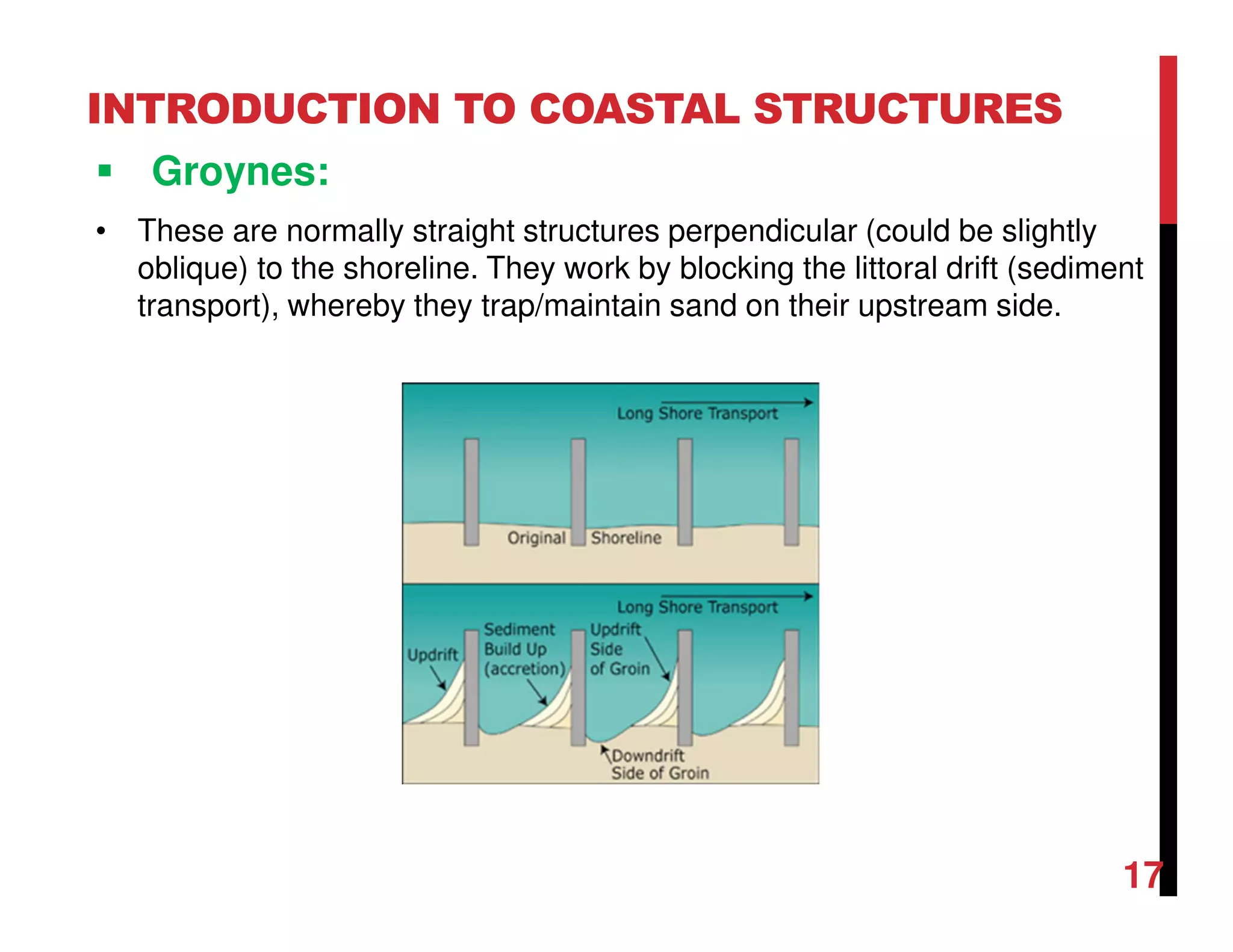
![INTRODUCTION TO COASTAL STRUCTURES
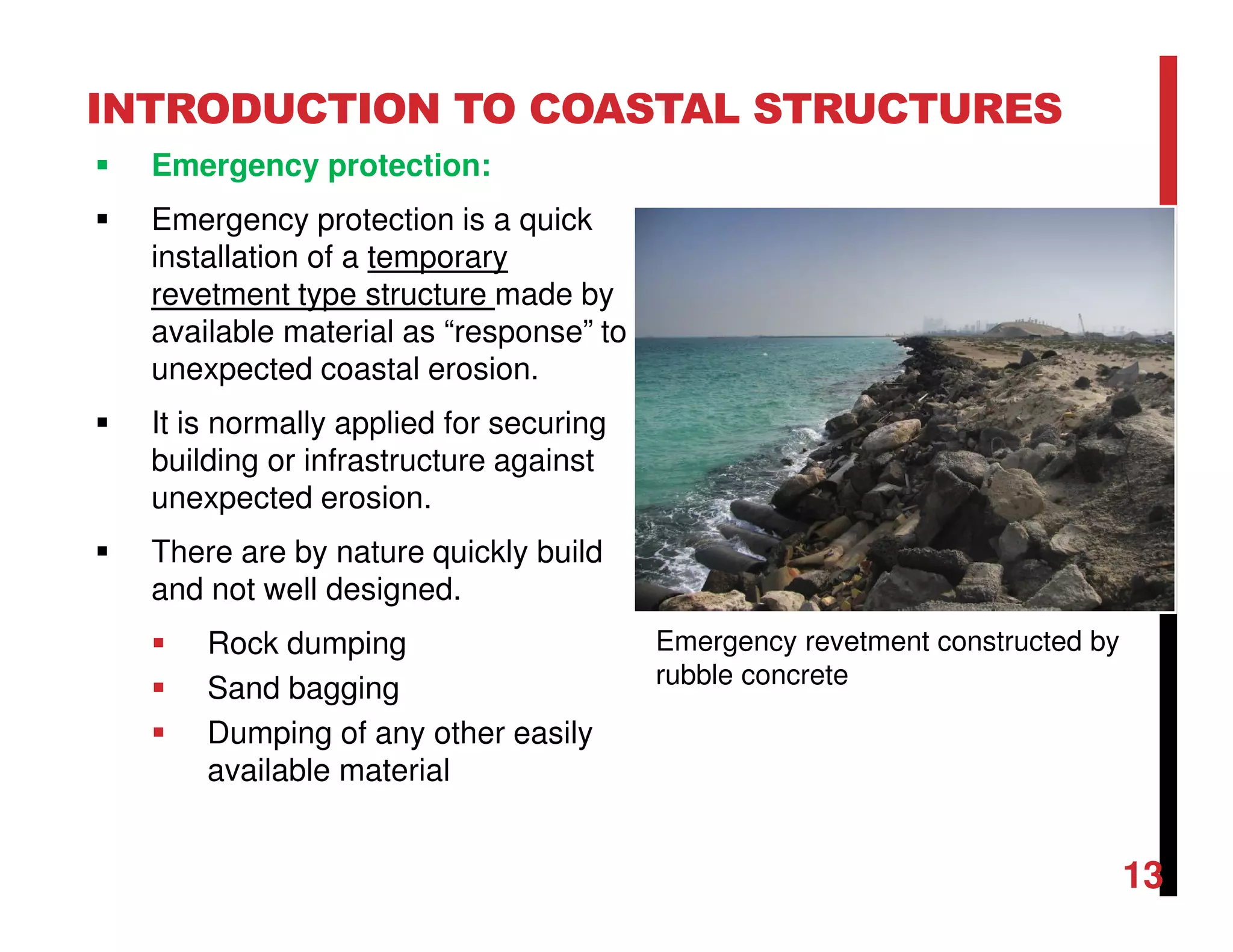
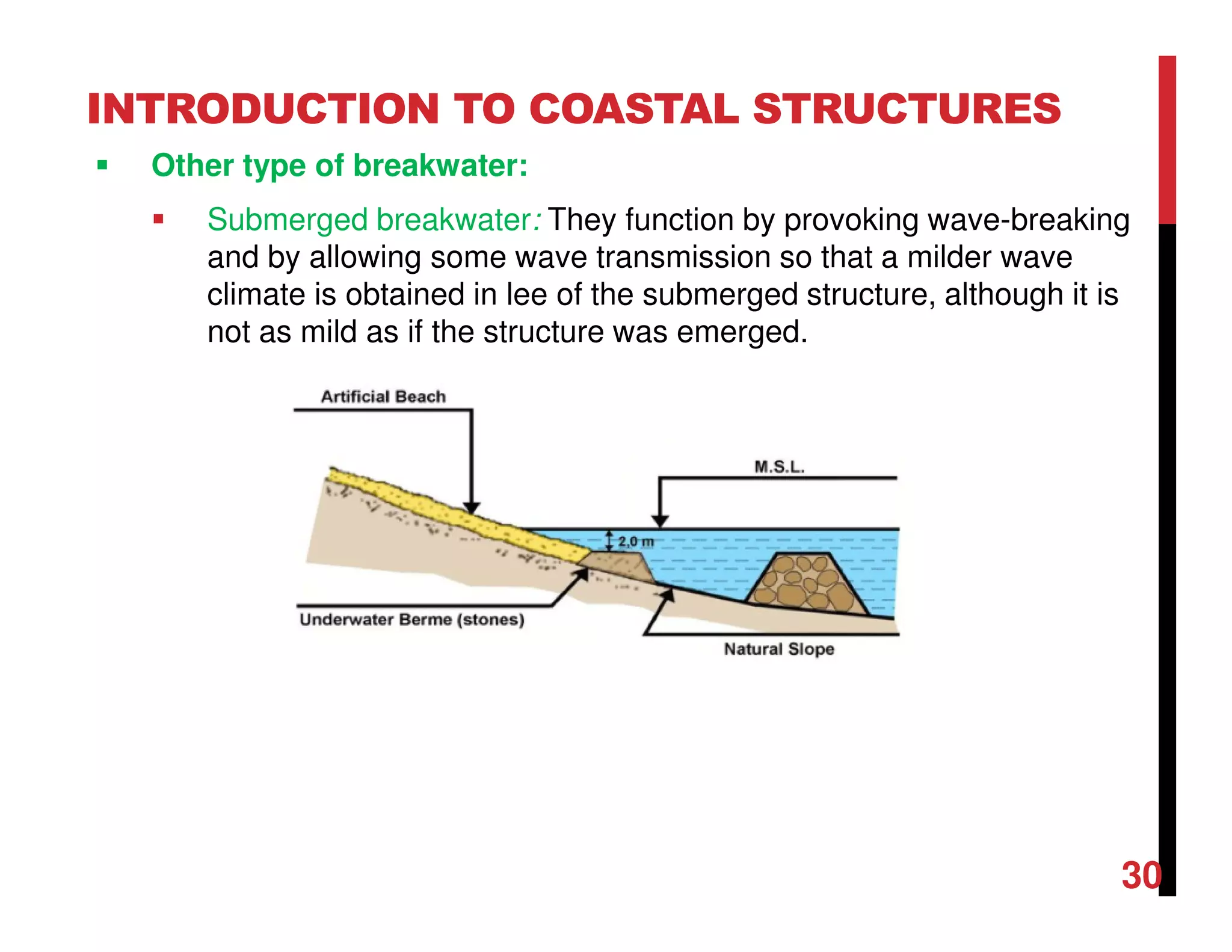
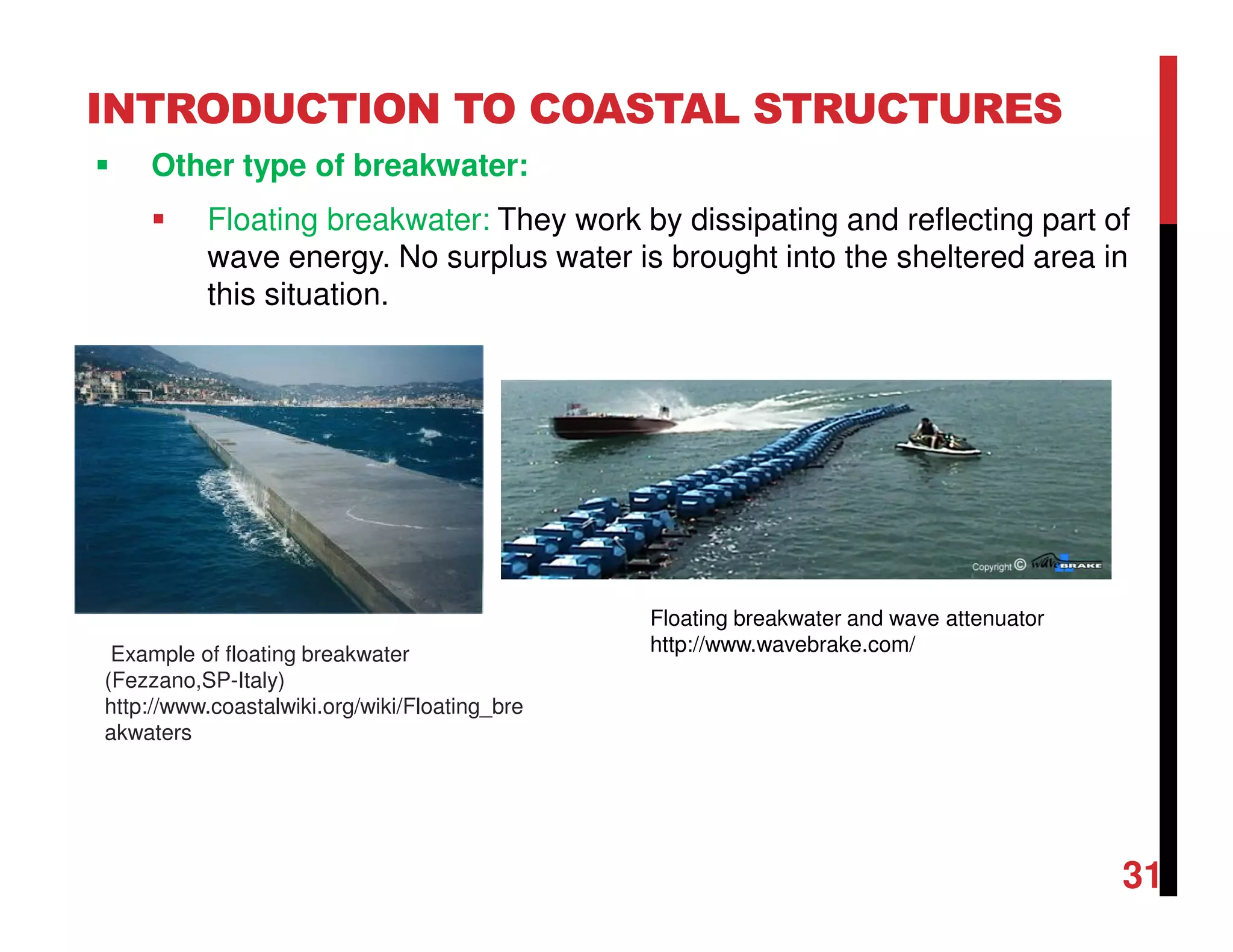
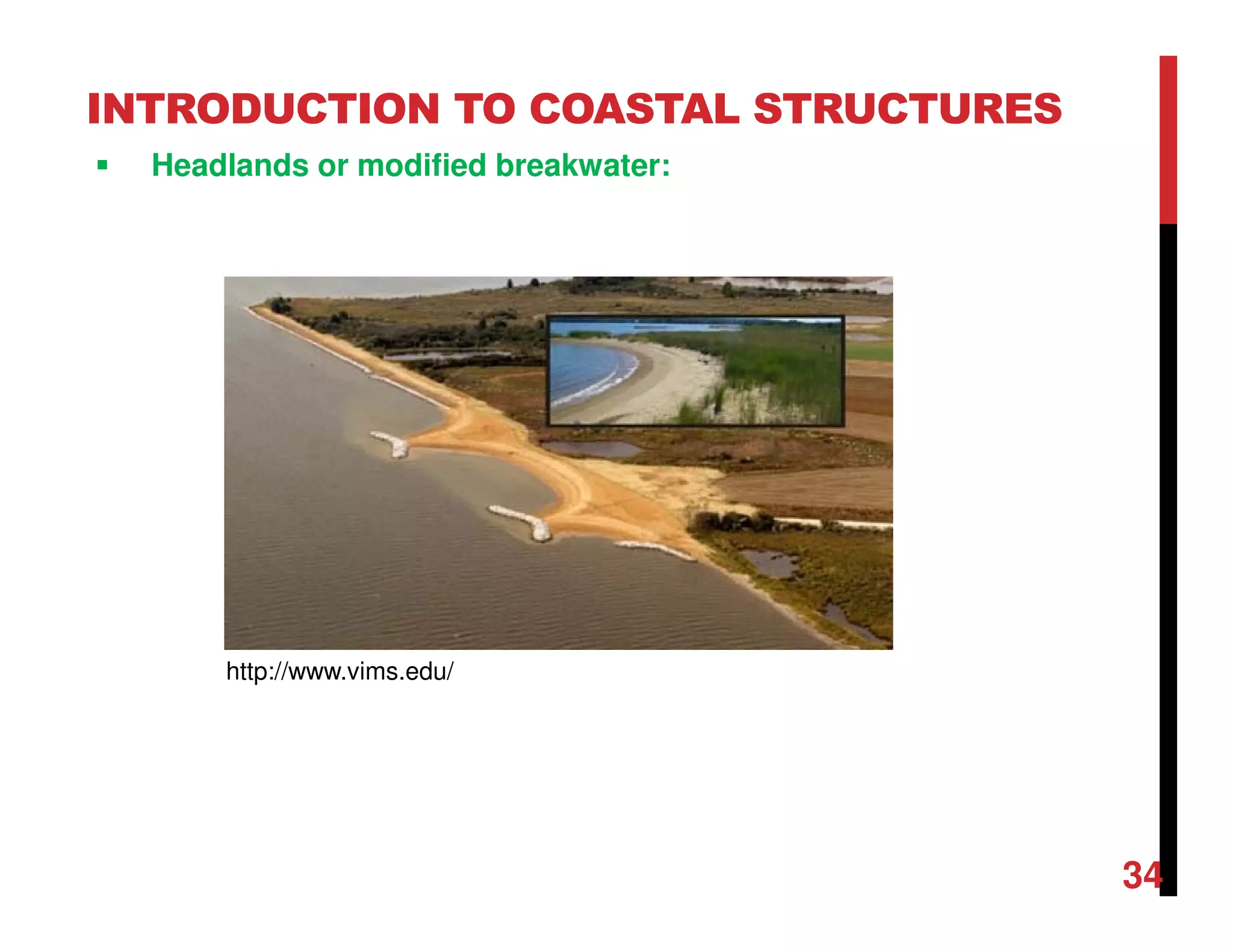
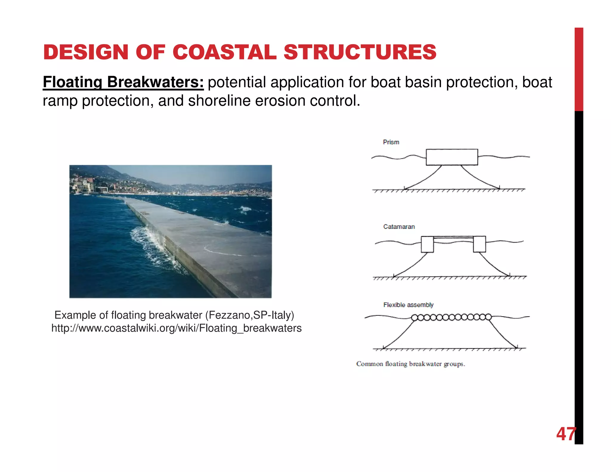
Other type of breakwater:
Special type breakwater: Various specially designed concrete
element type submerged and permeable breakwaters and flexible
tube breakwaters have been introduced onto the market.
32
Geo-textile Tubes for Breakwaters and Beach
Restoration in Mexico [https://www.geosynthetica.net/]](https://image.slidesharecdn.com/chapter5coastalstructures-180204113034/75/Chapter-5-coastal-structures-32-2048.jpg)

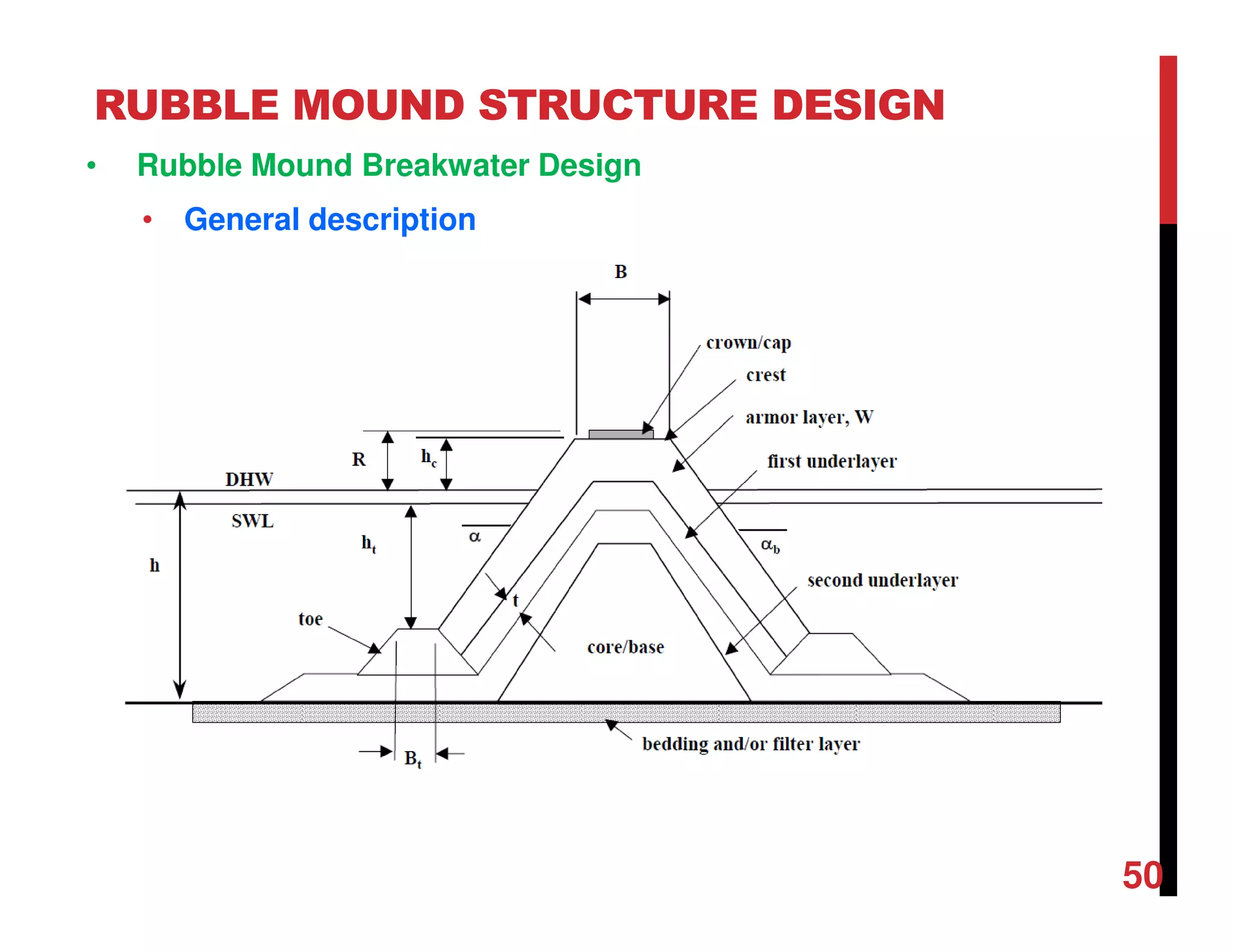
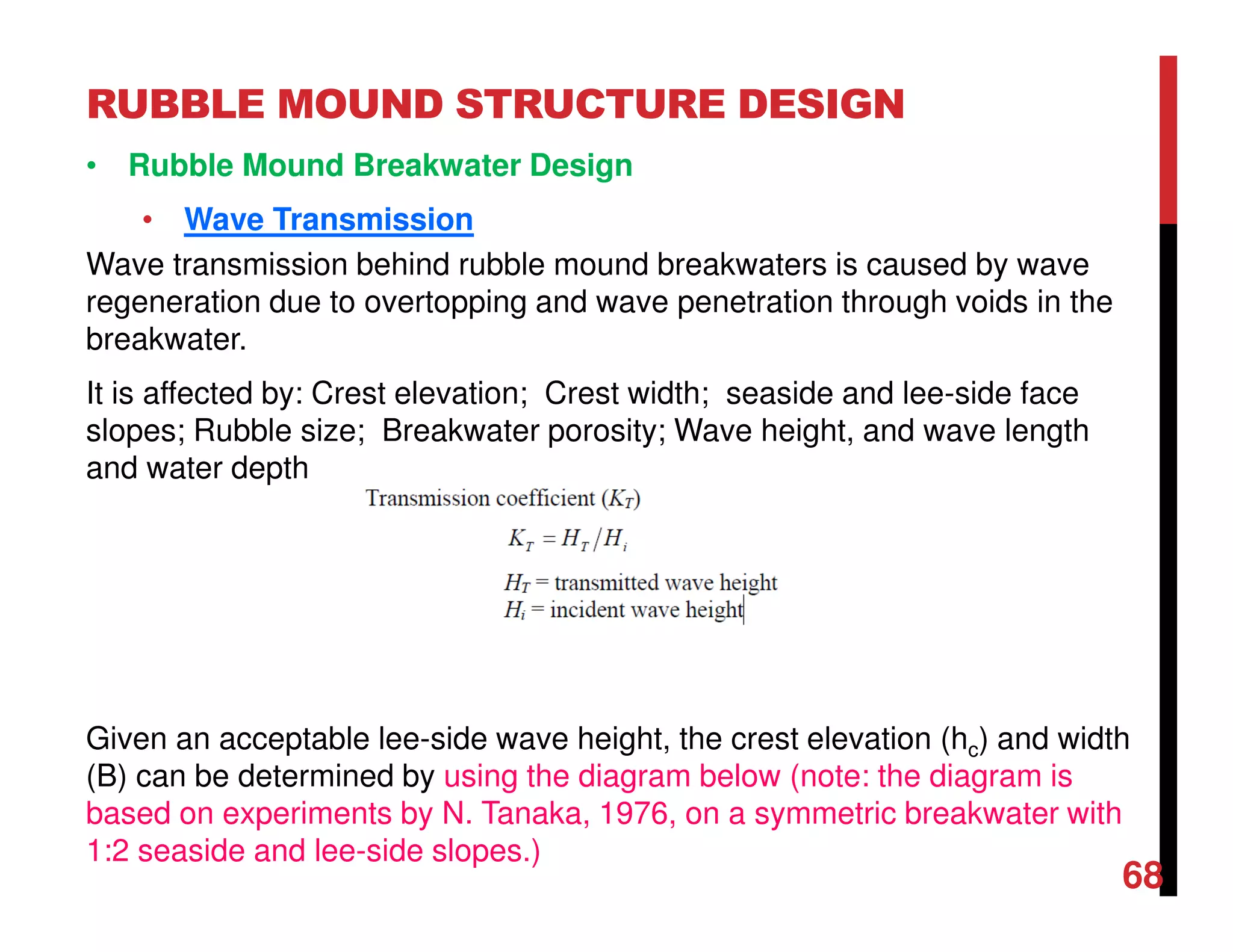
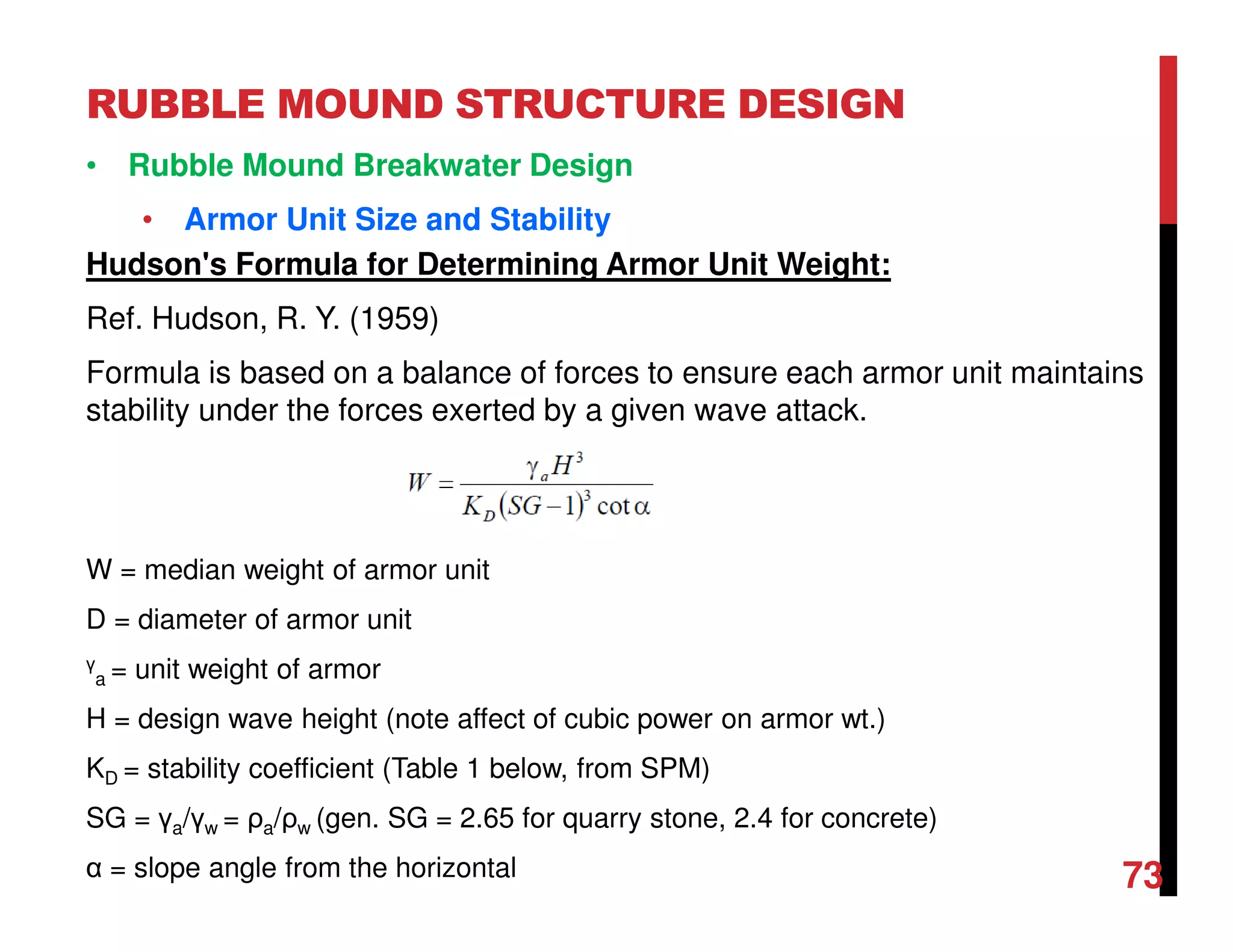
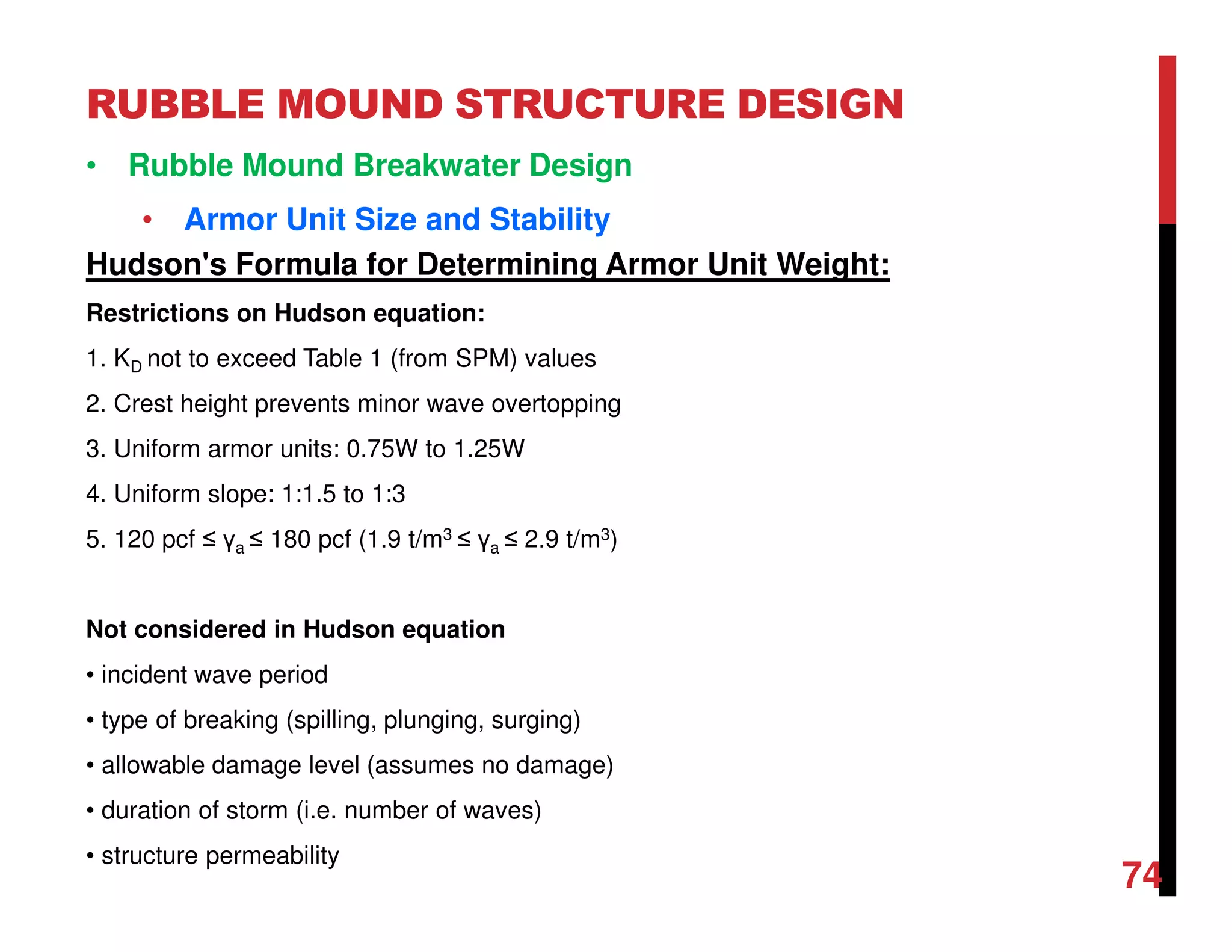
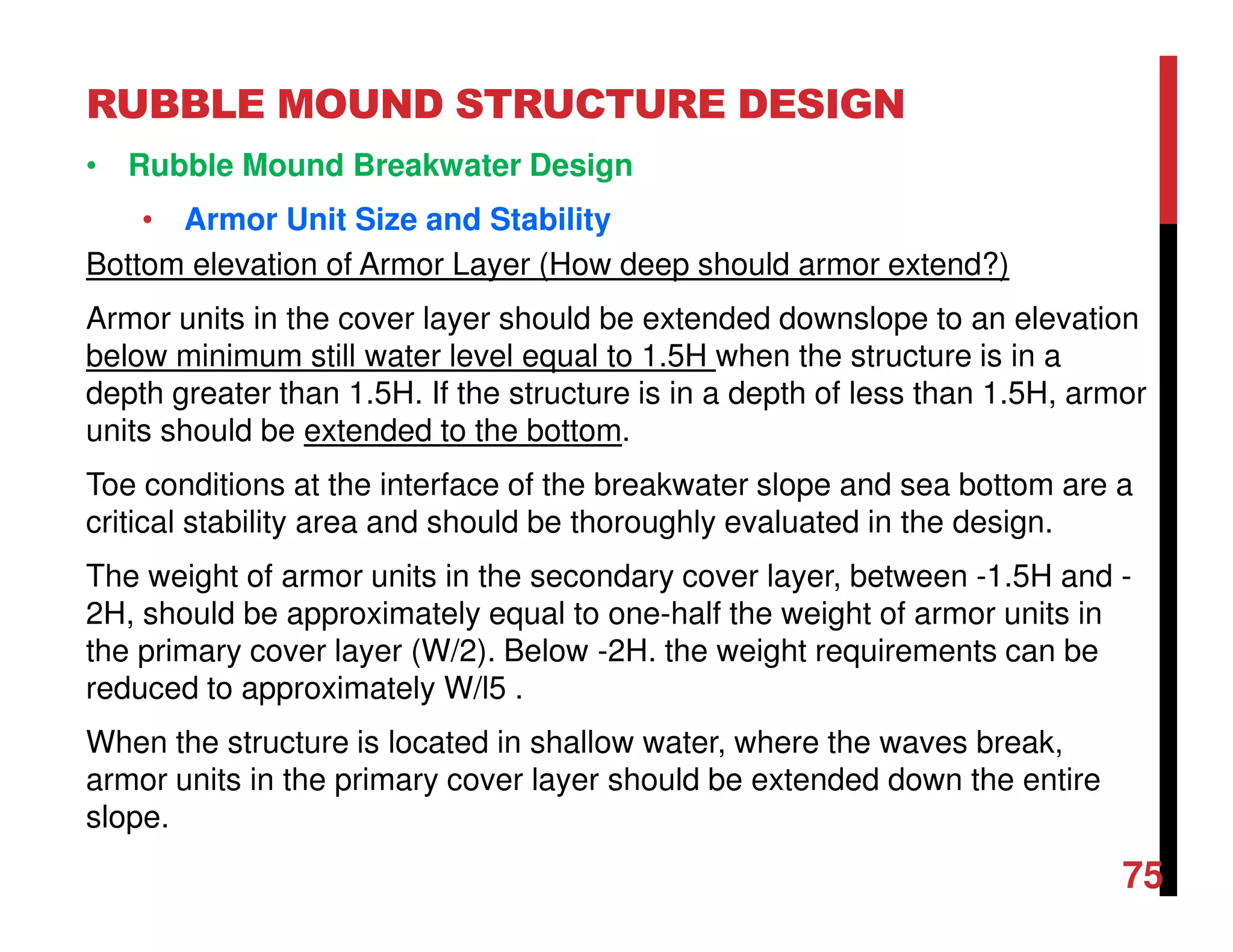
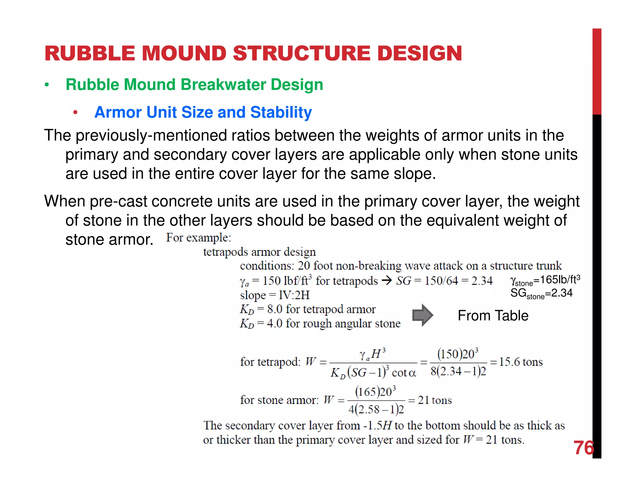
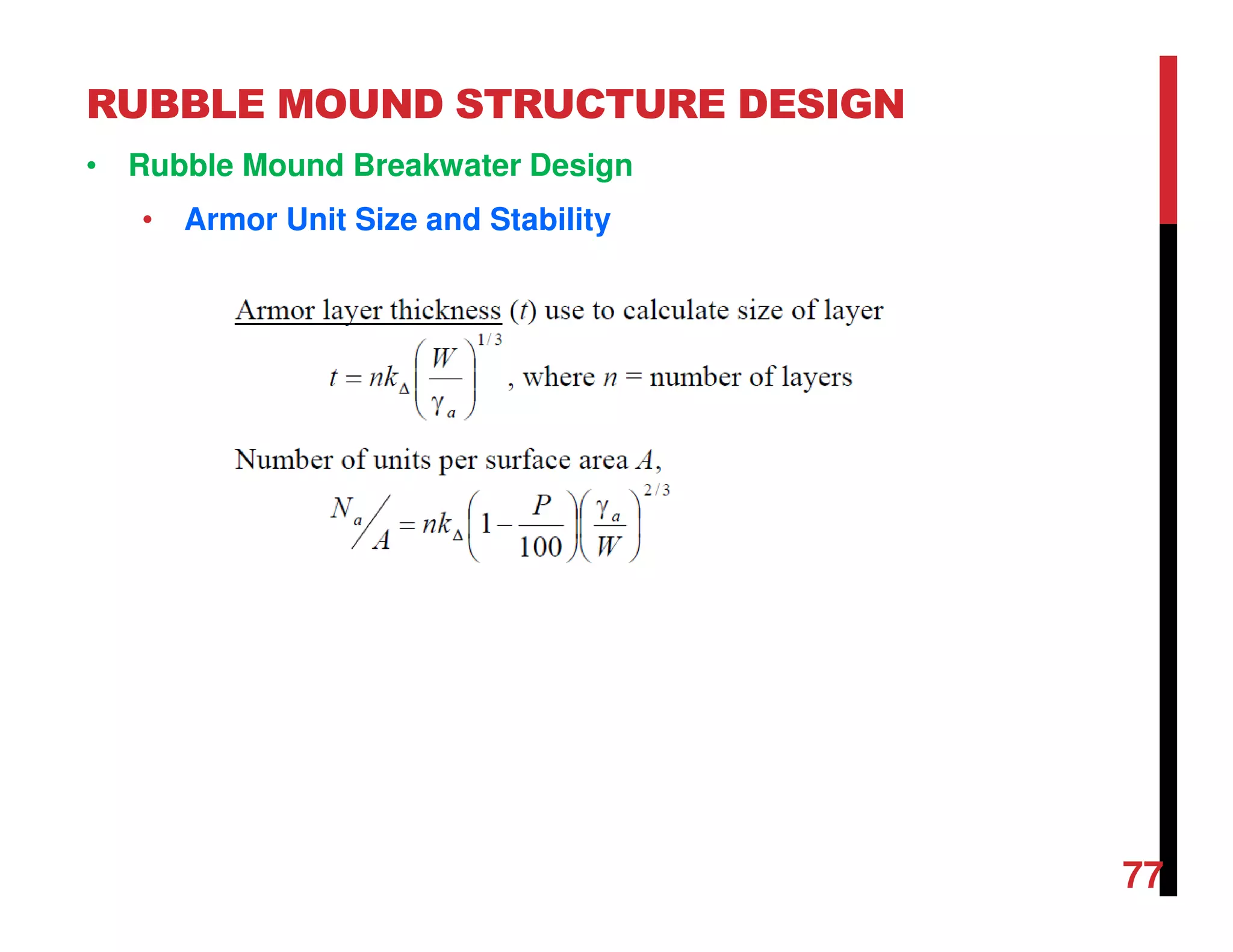
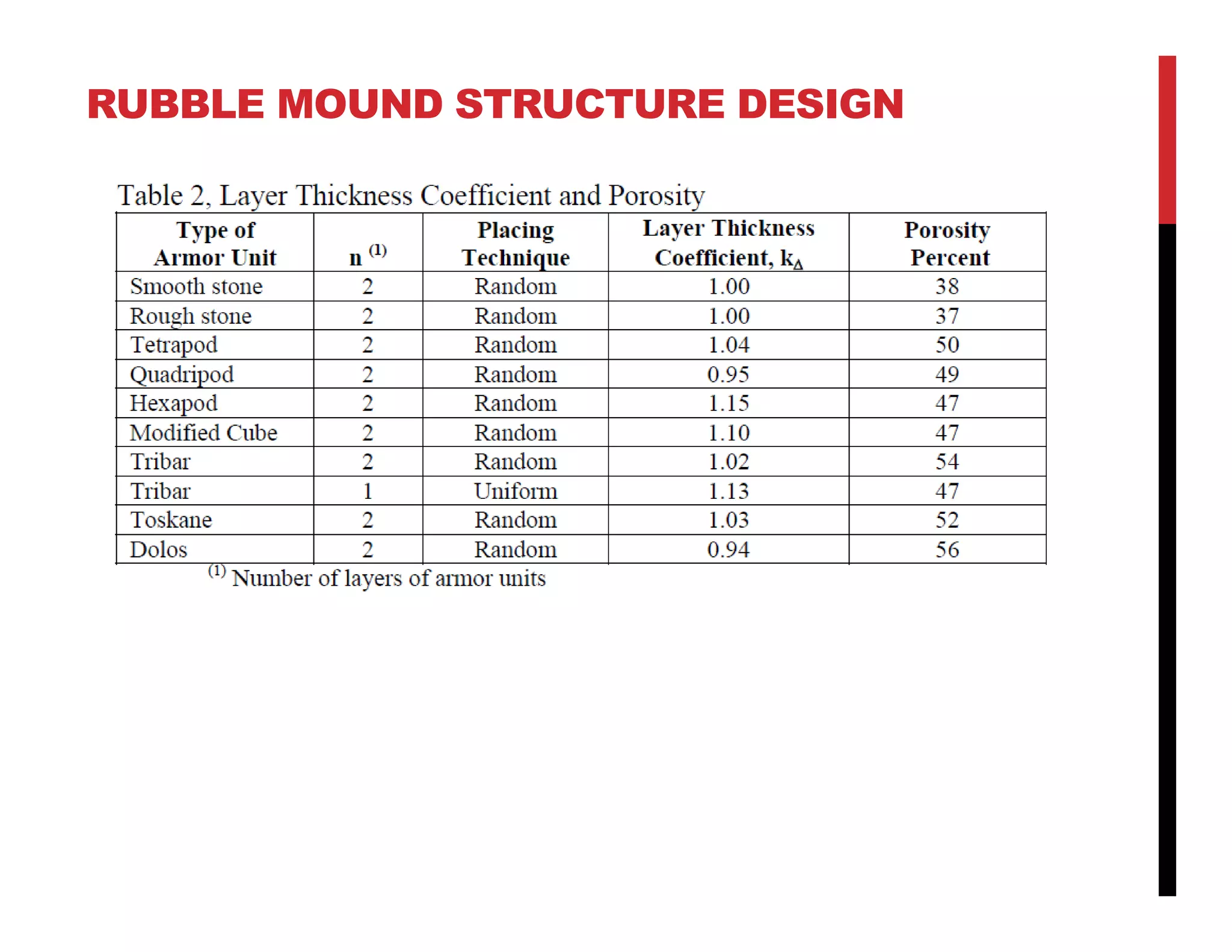
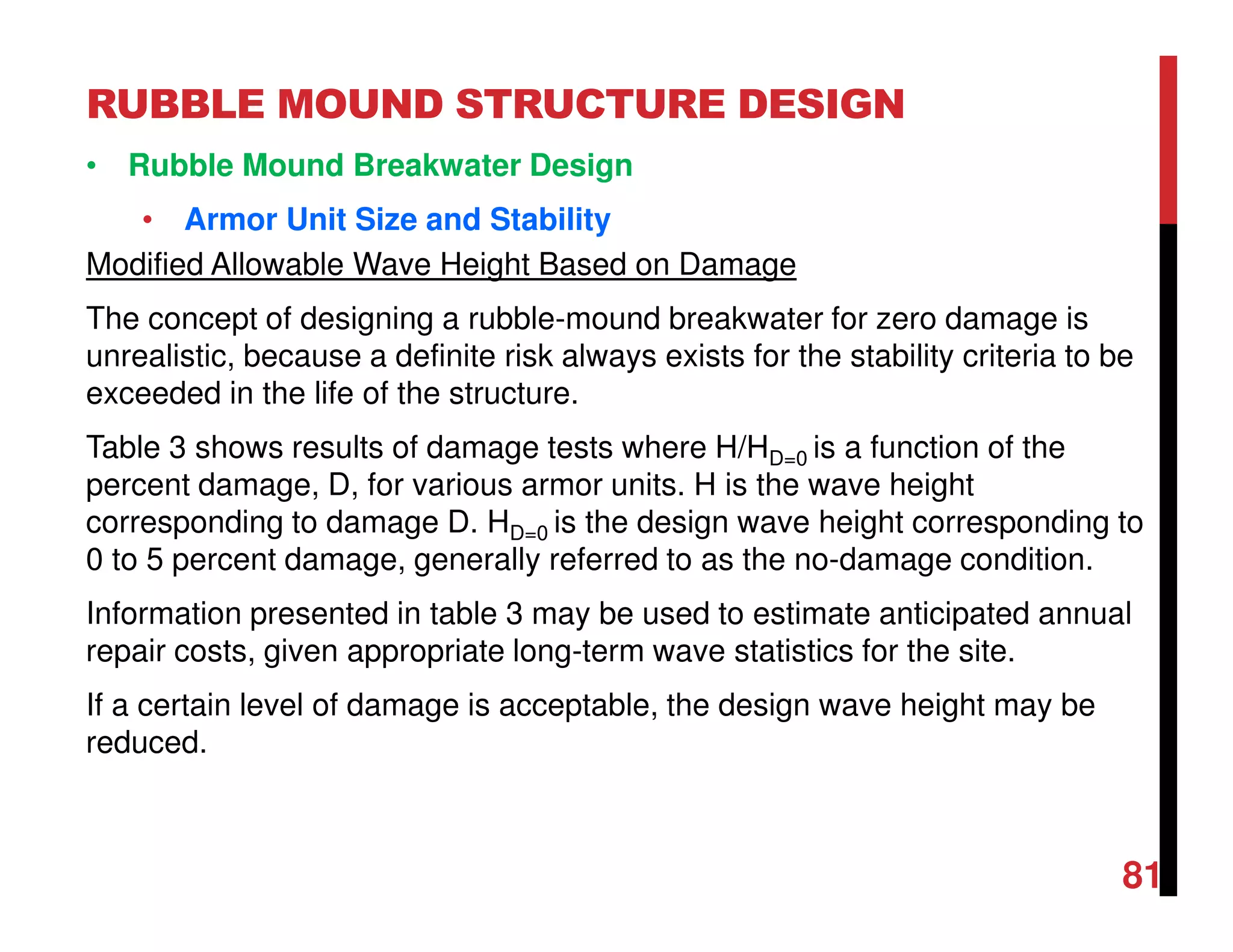
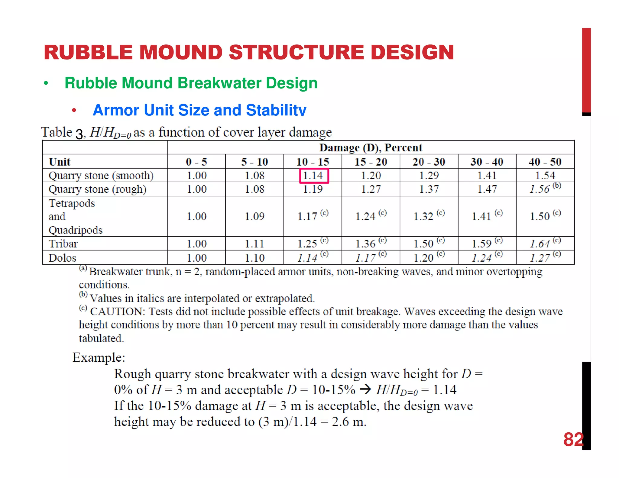
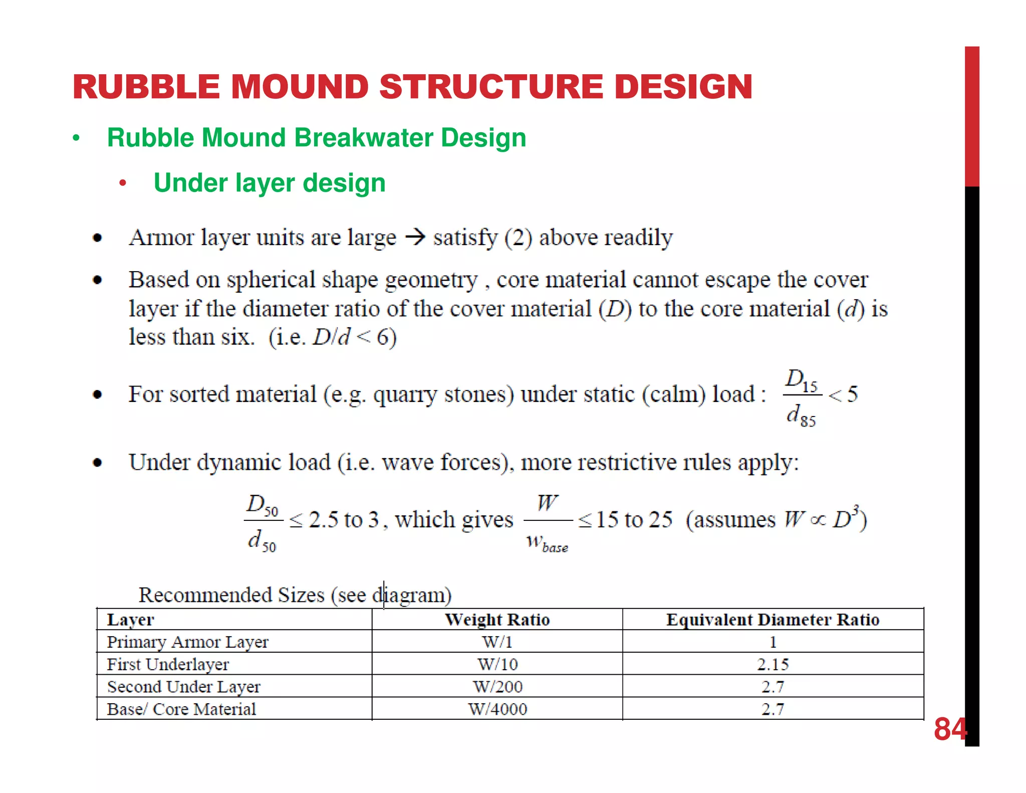
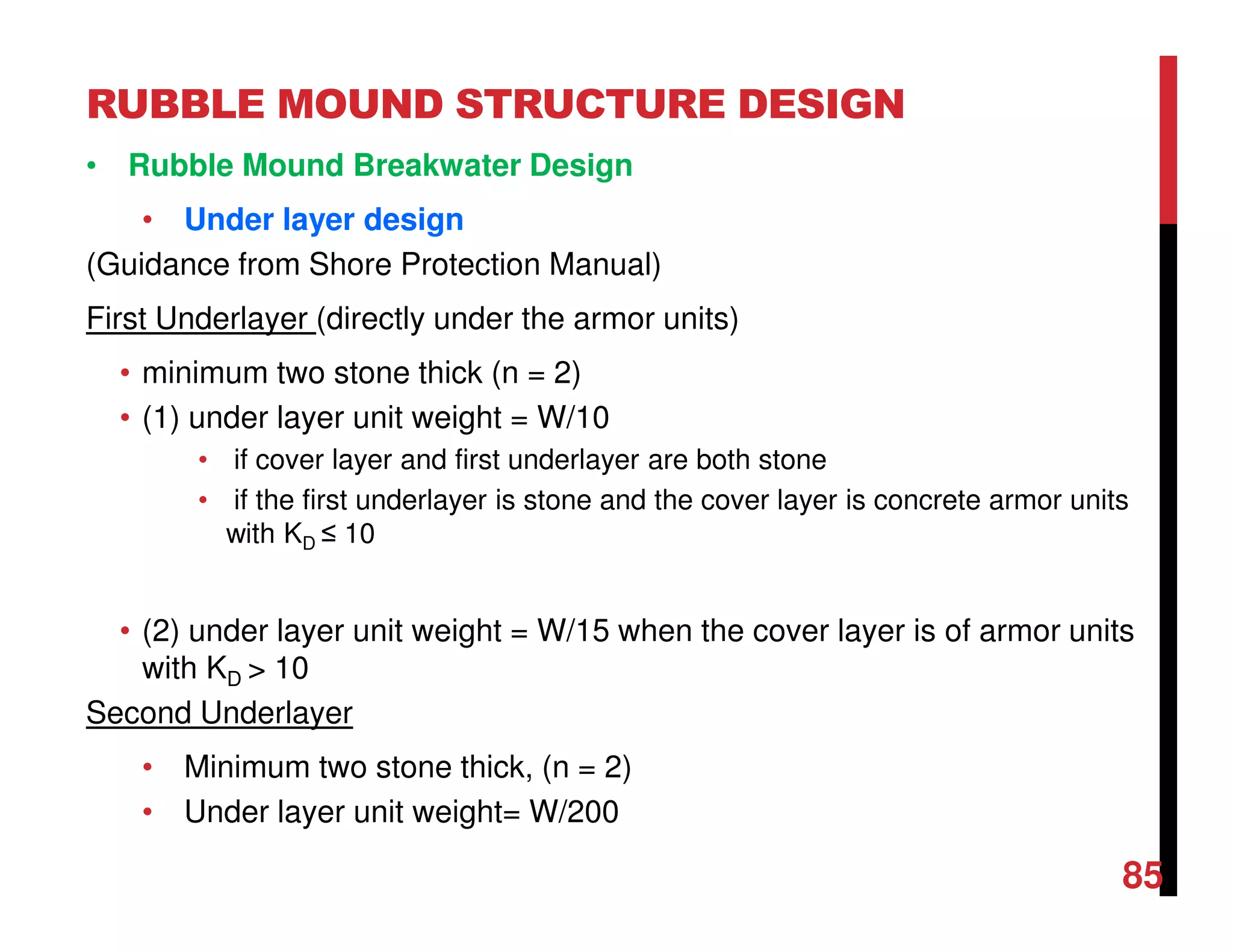
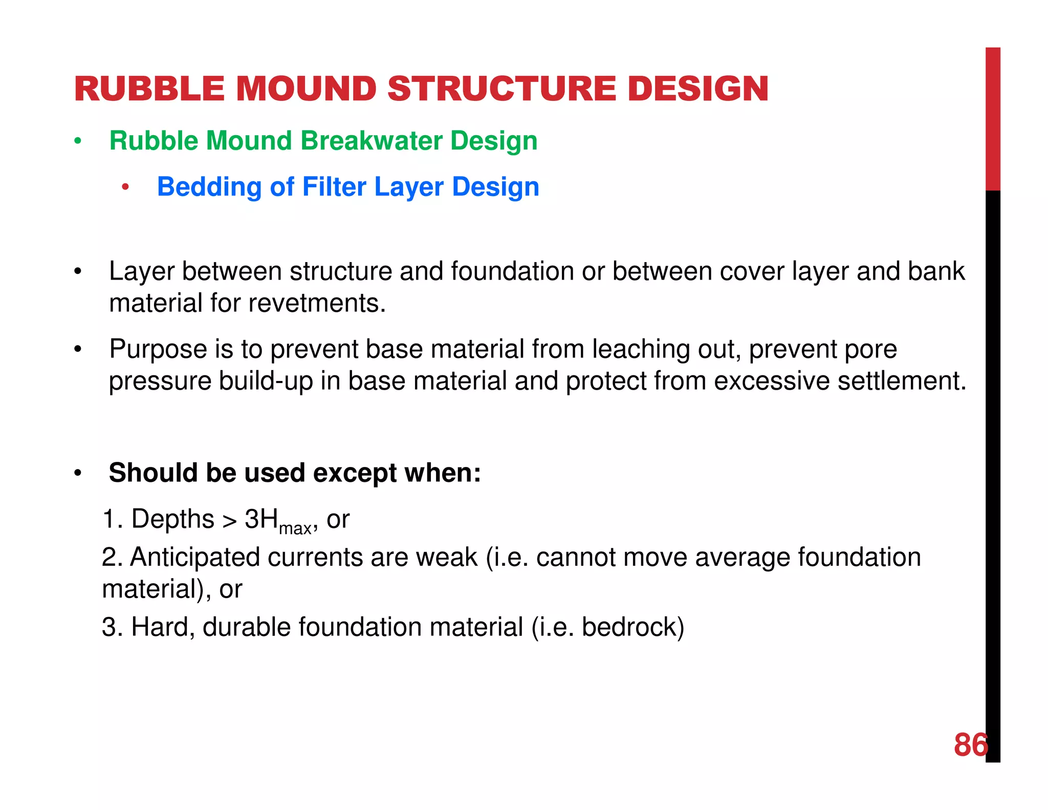
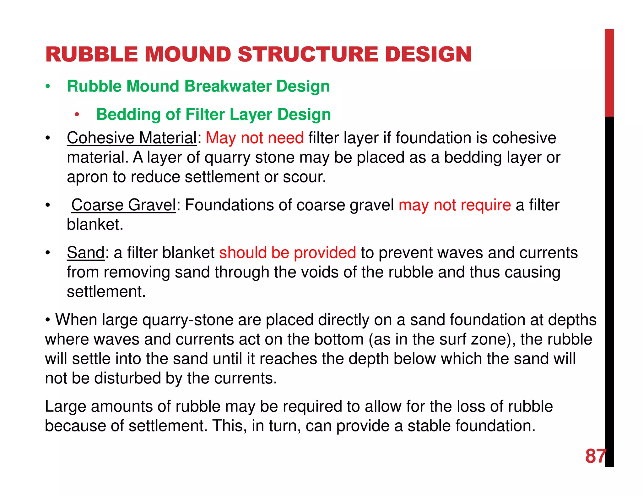
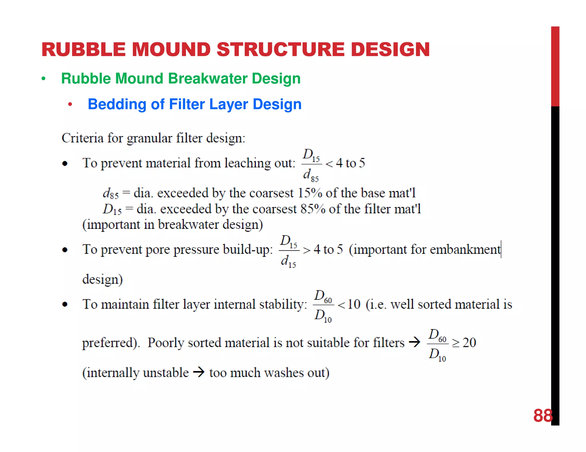
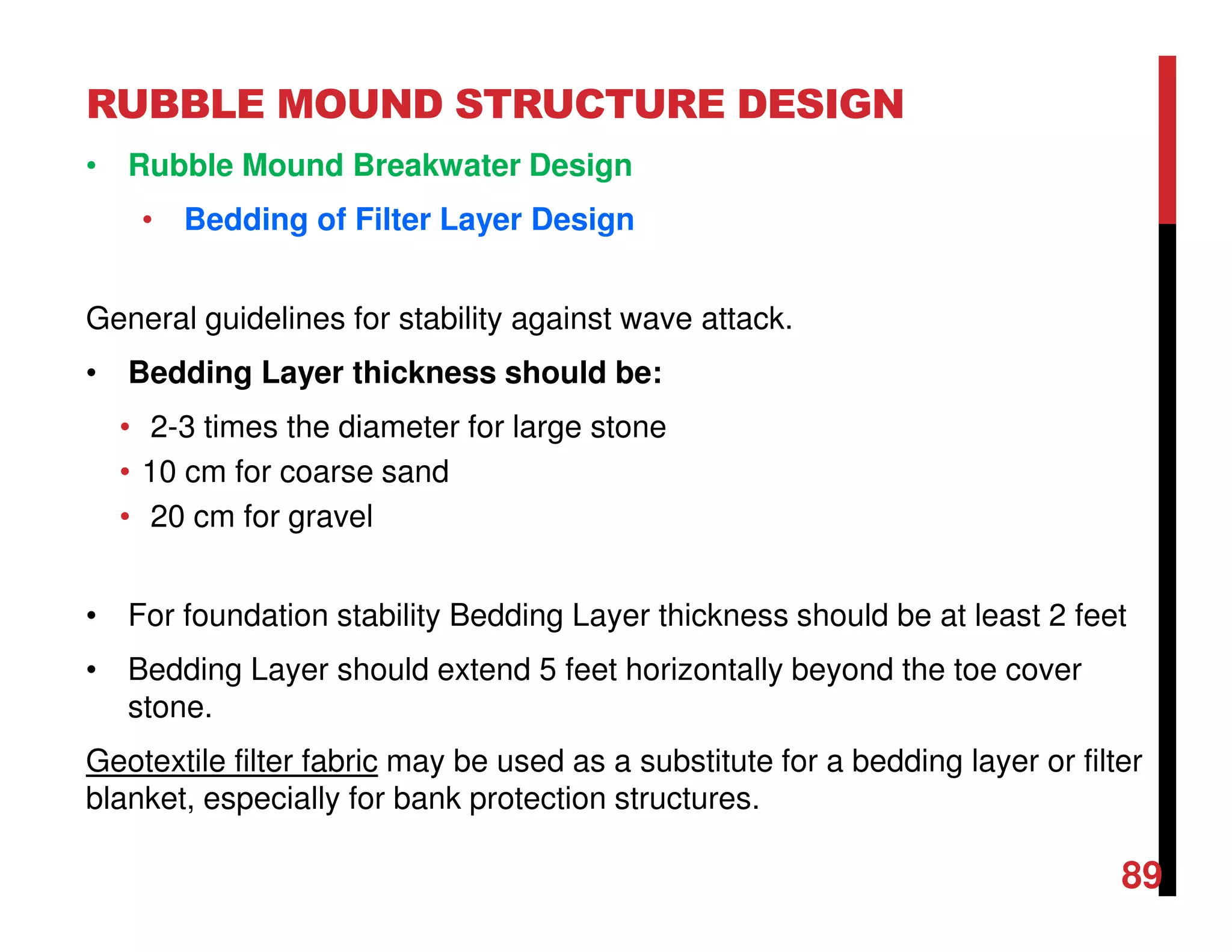
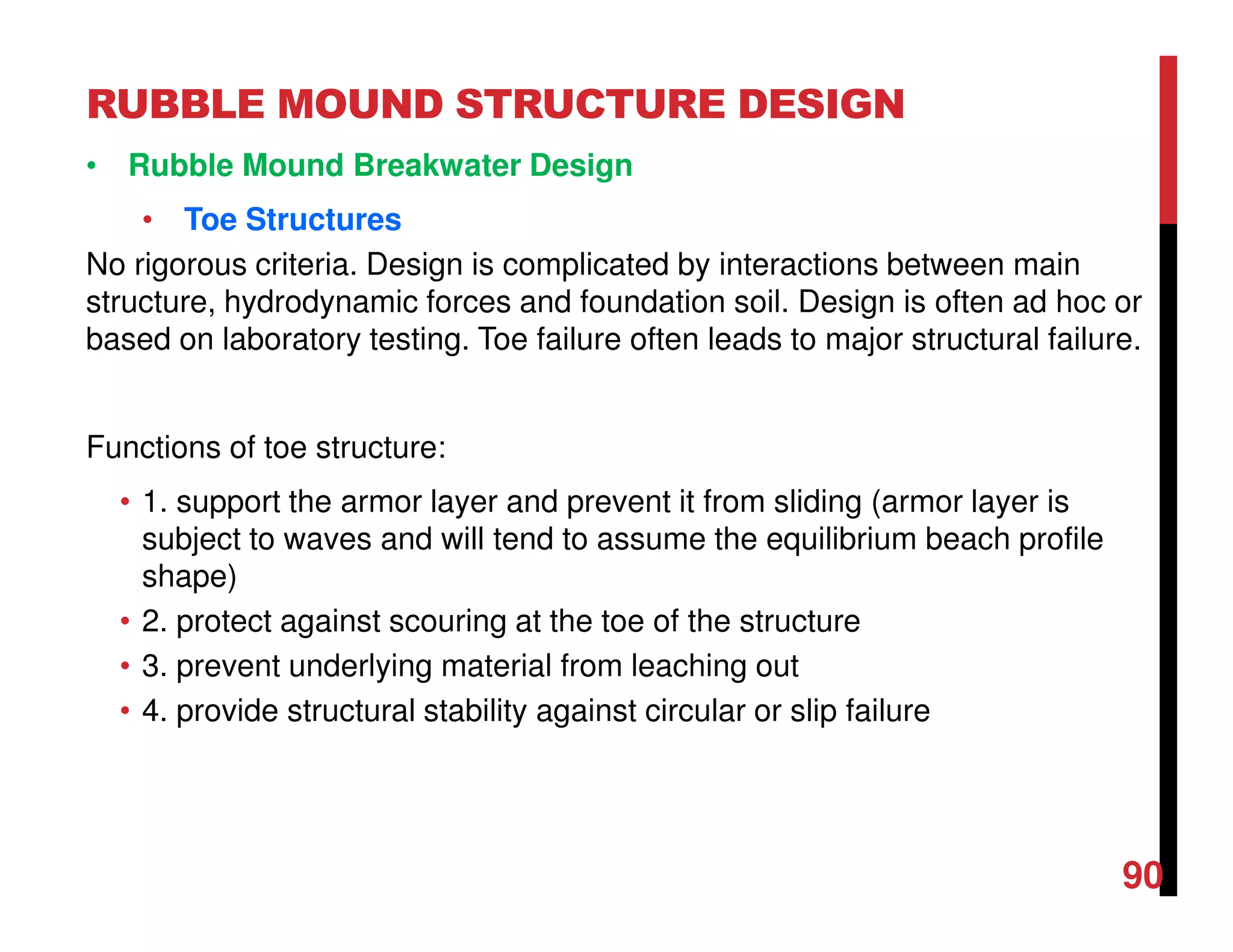
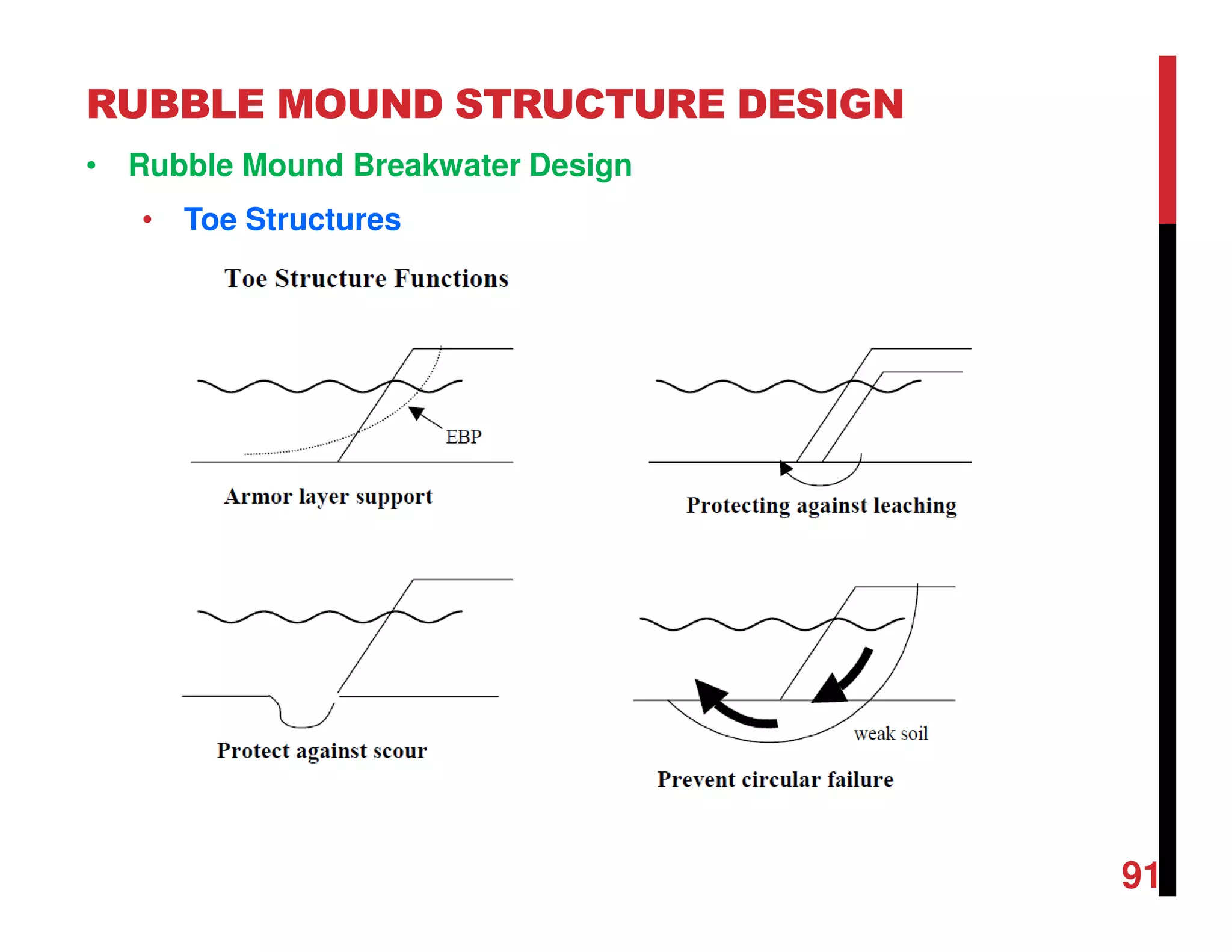
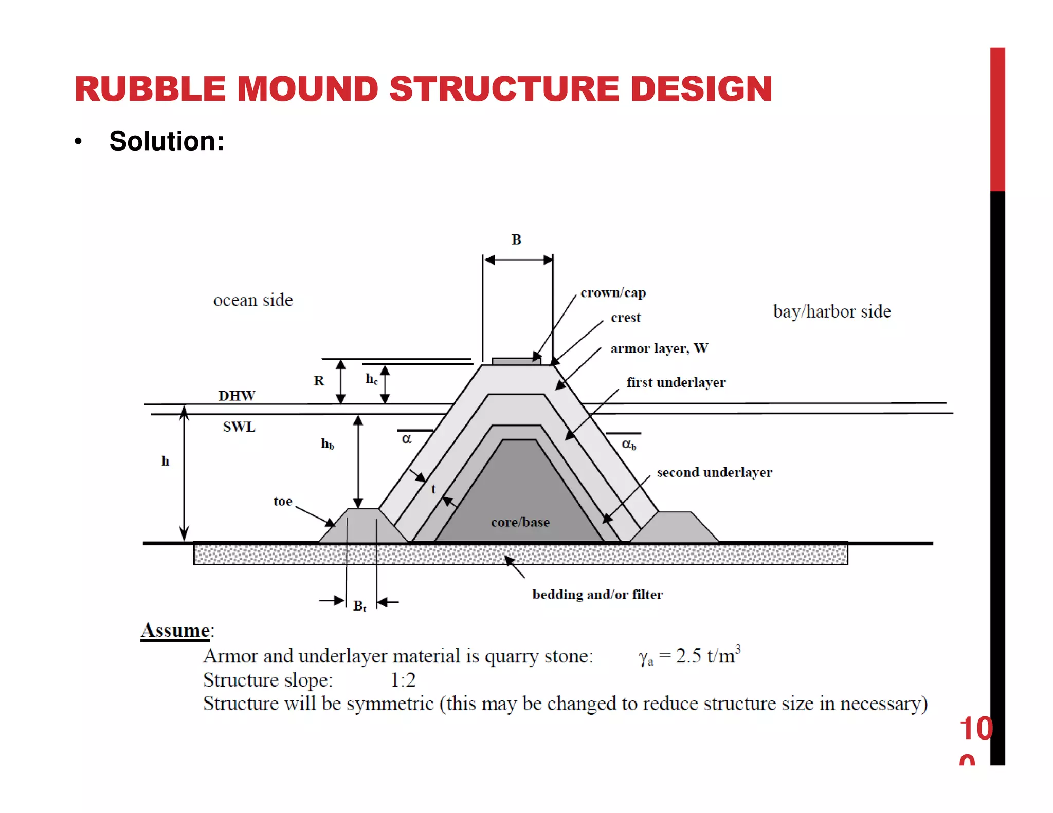
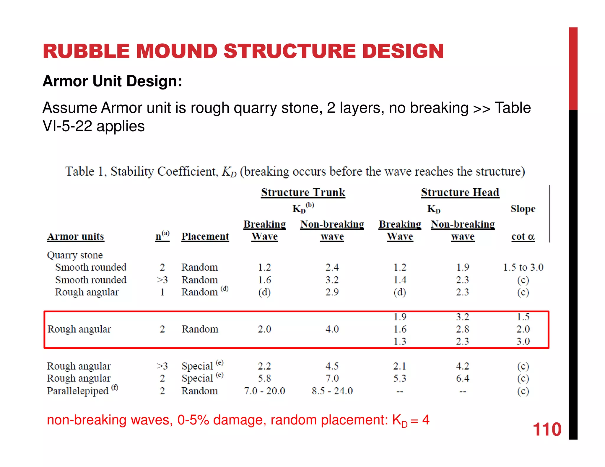
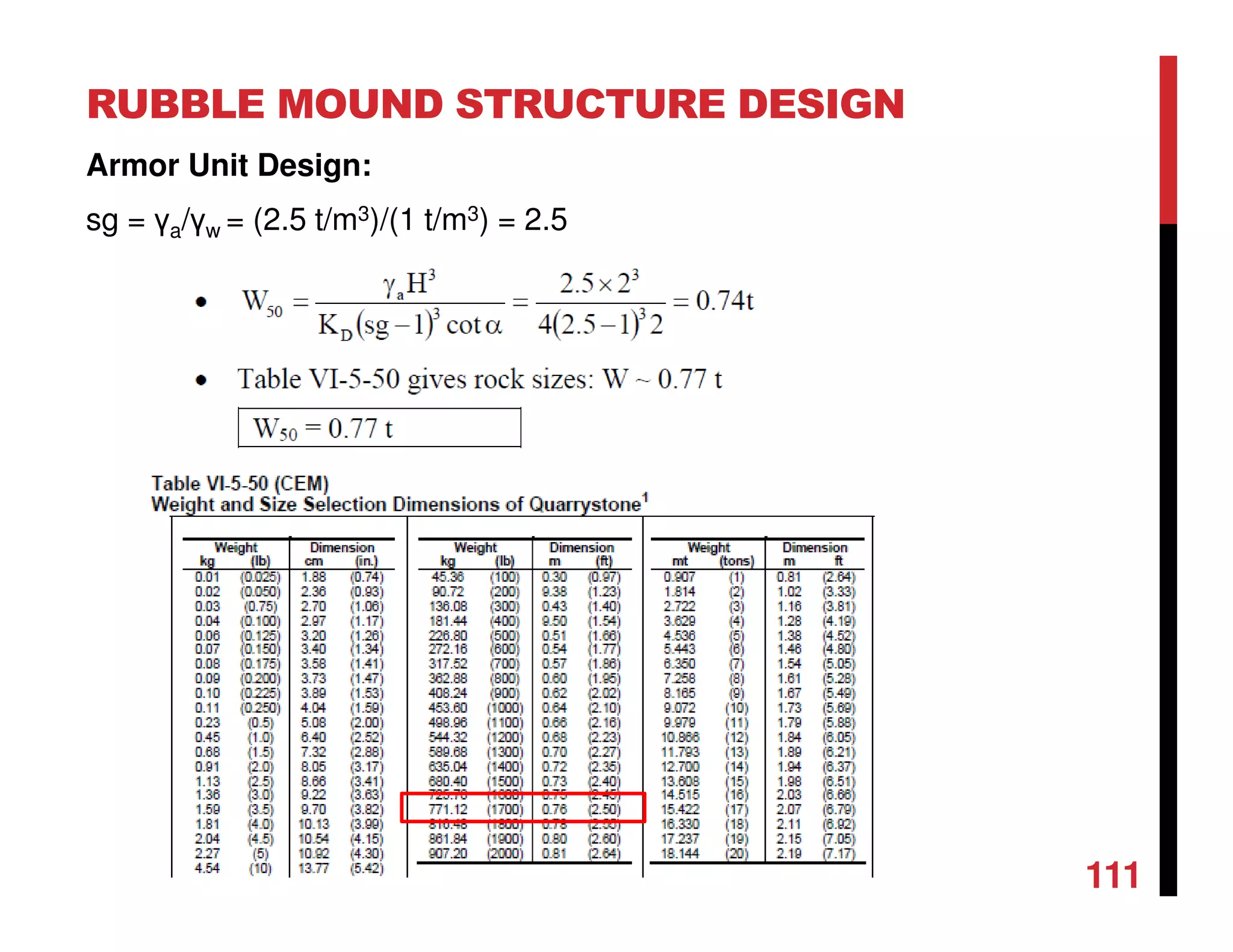
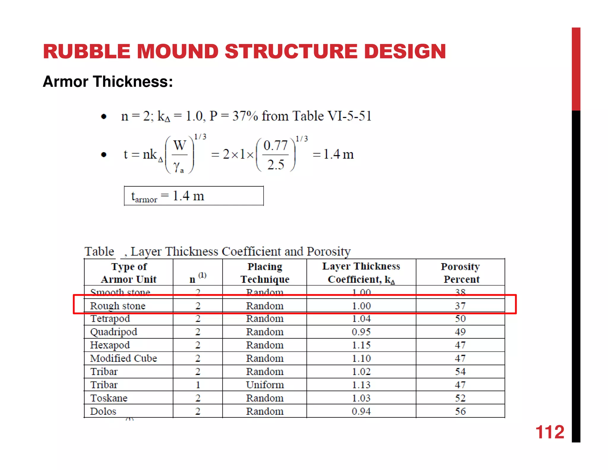
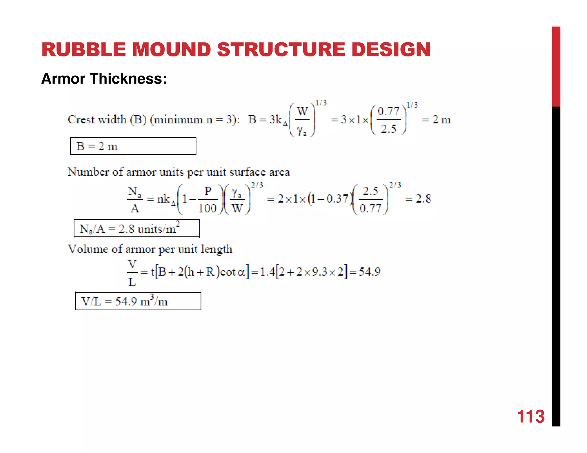
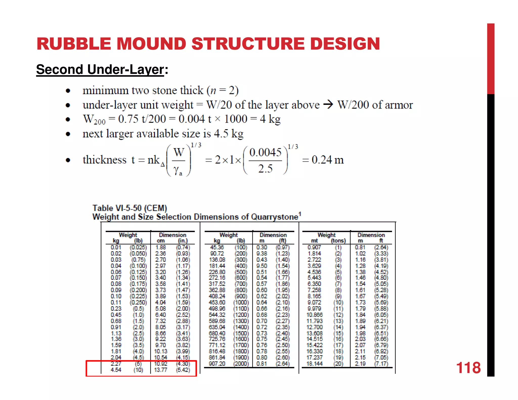
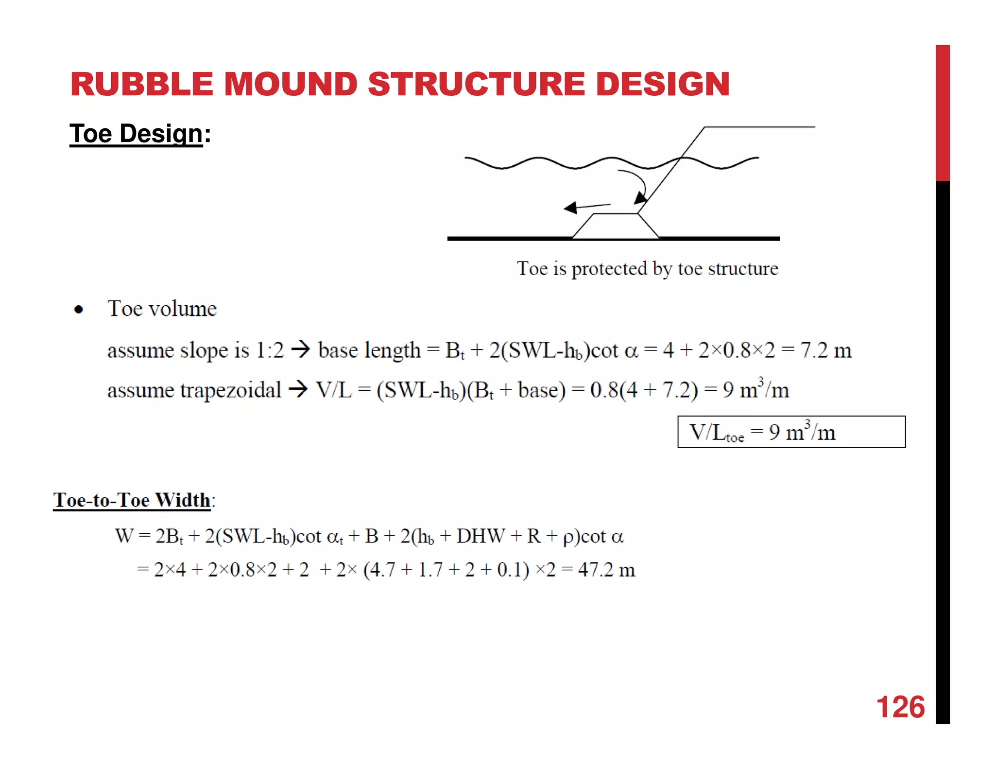
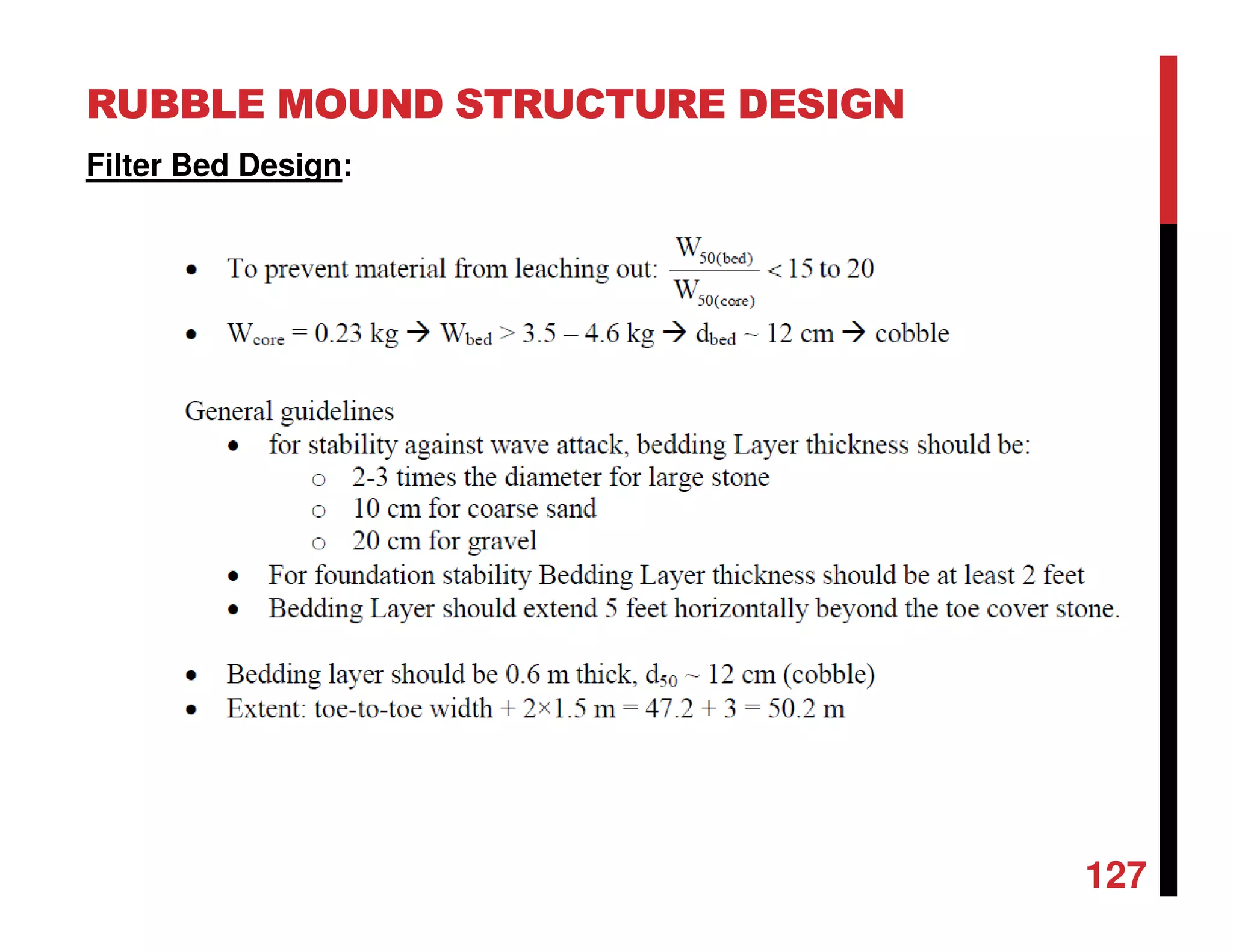
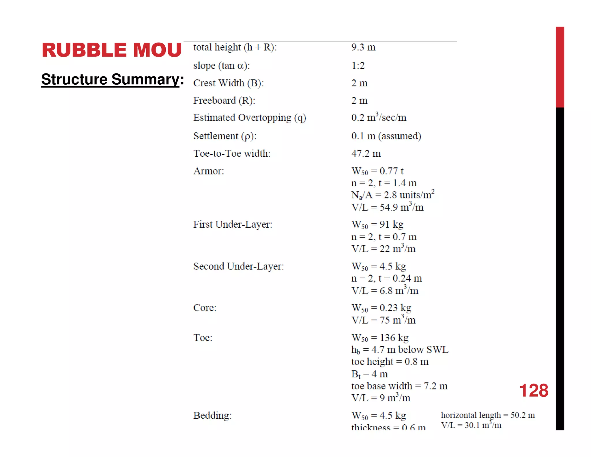
![RUBBLE MOUND STRUCTURE DESIGN
62
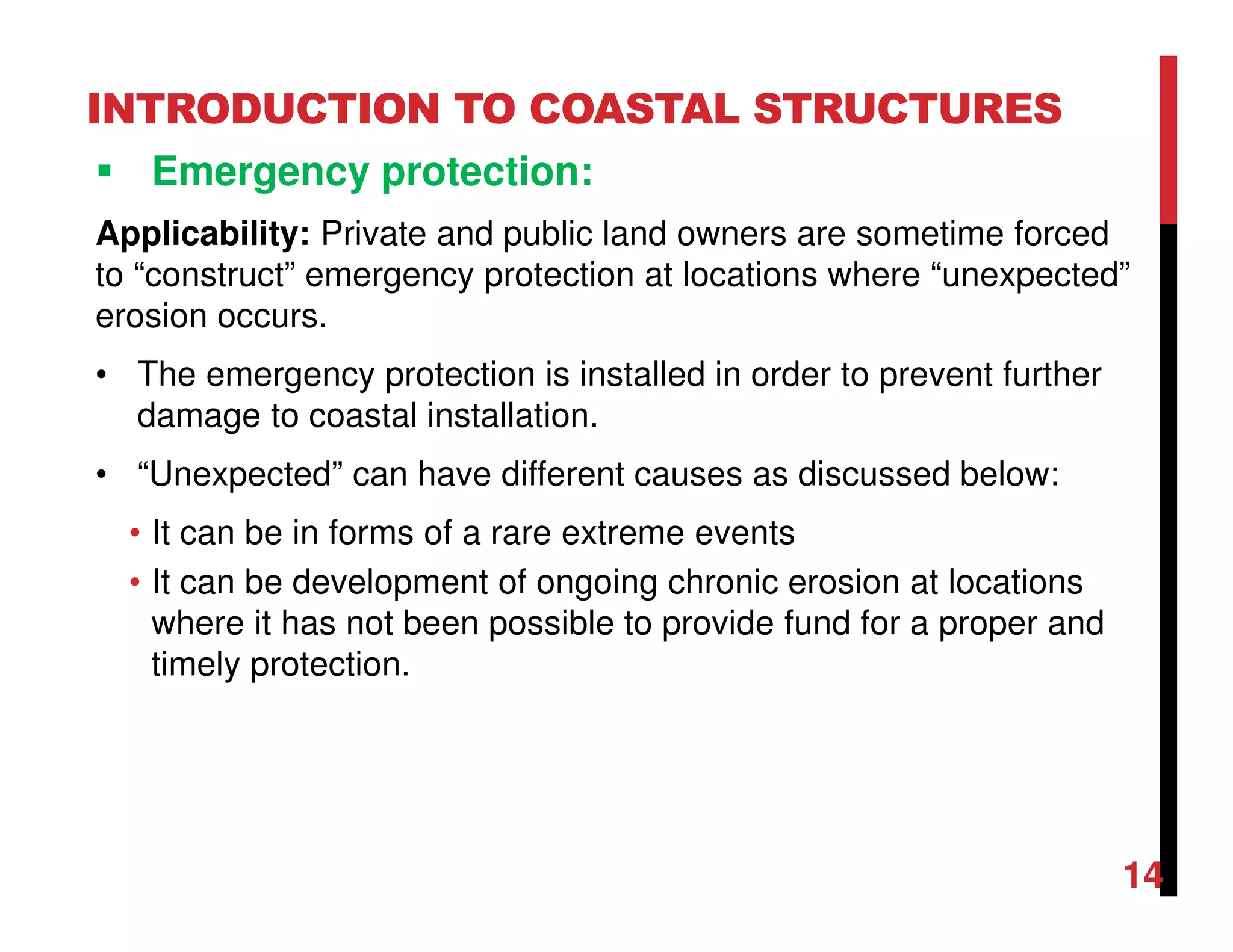
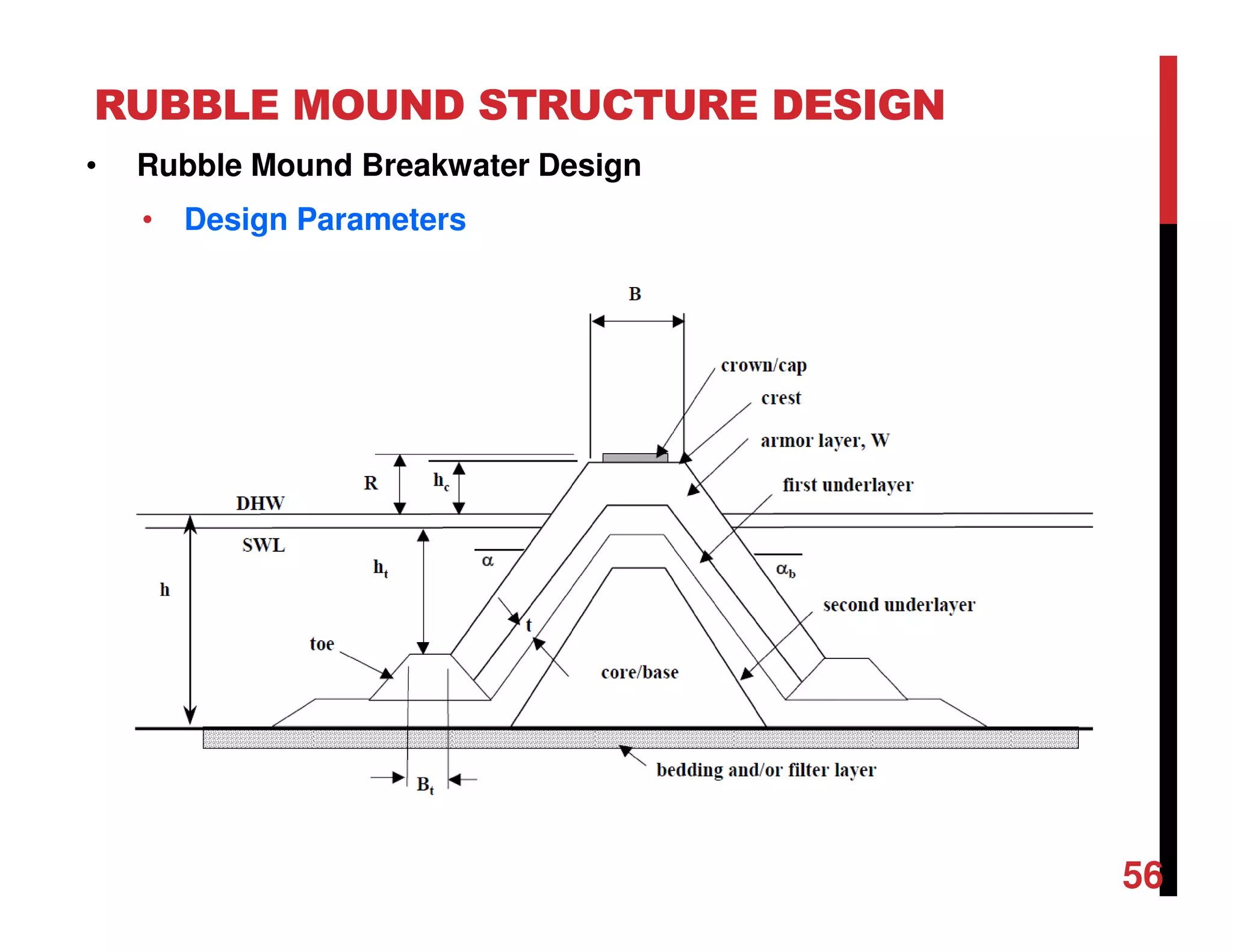
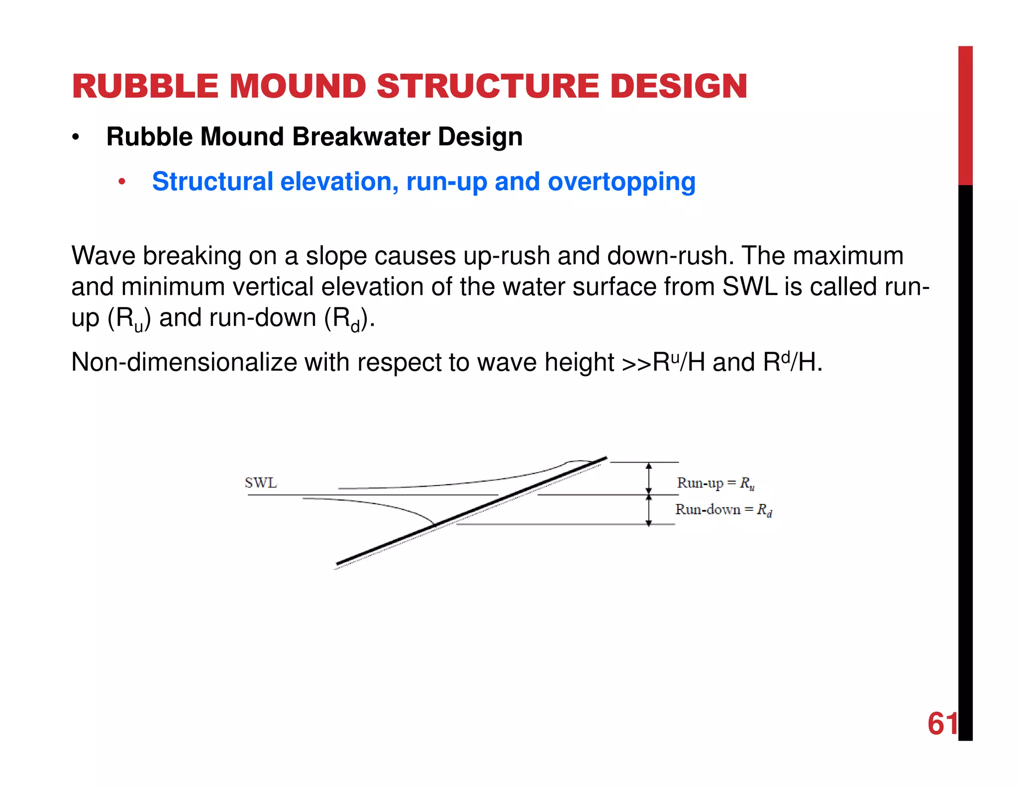
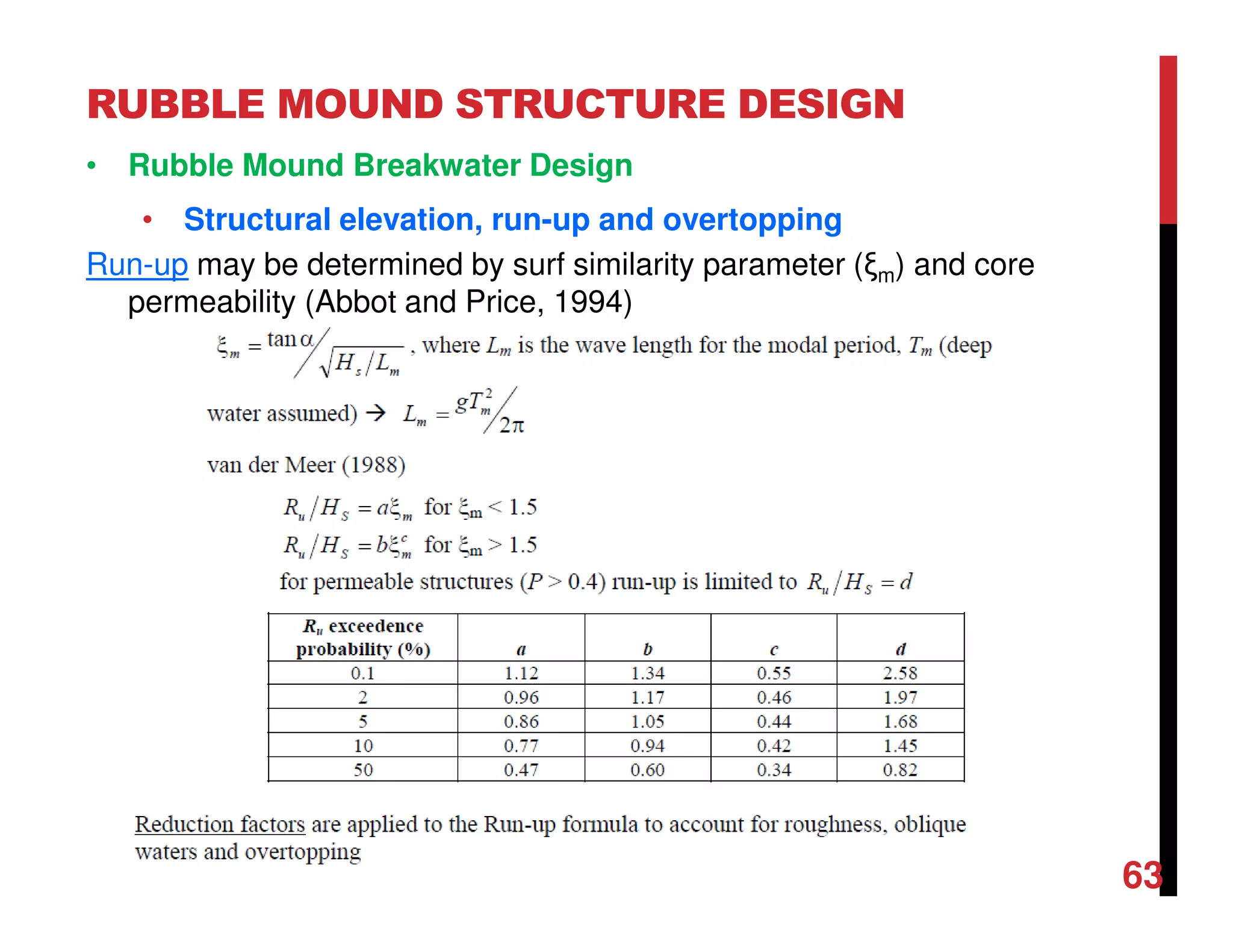
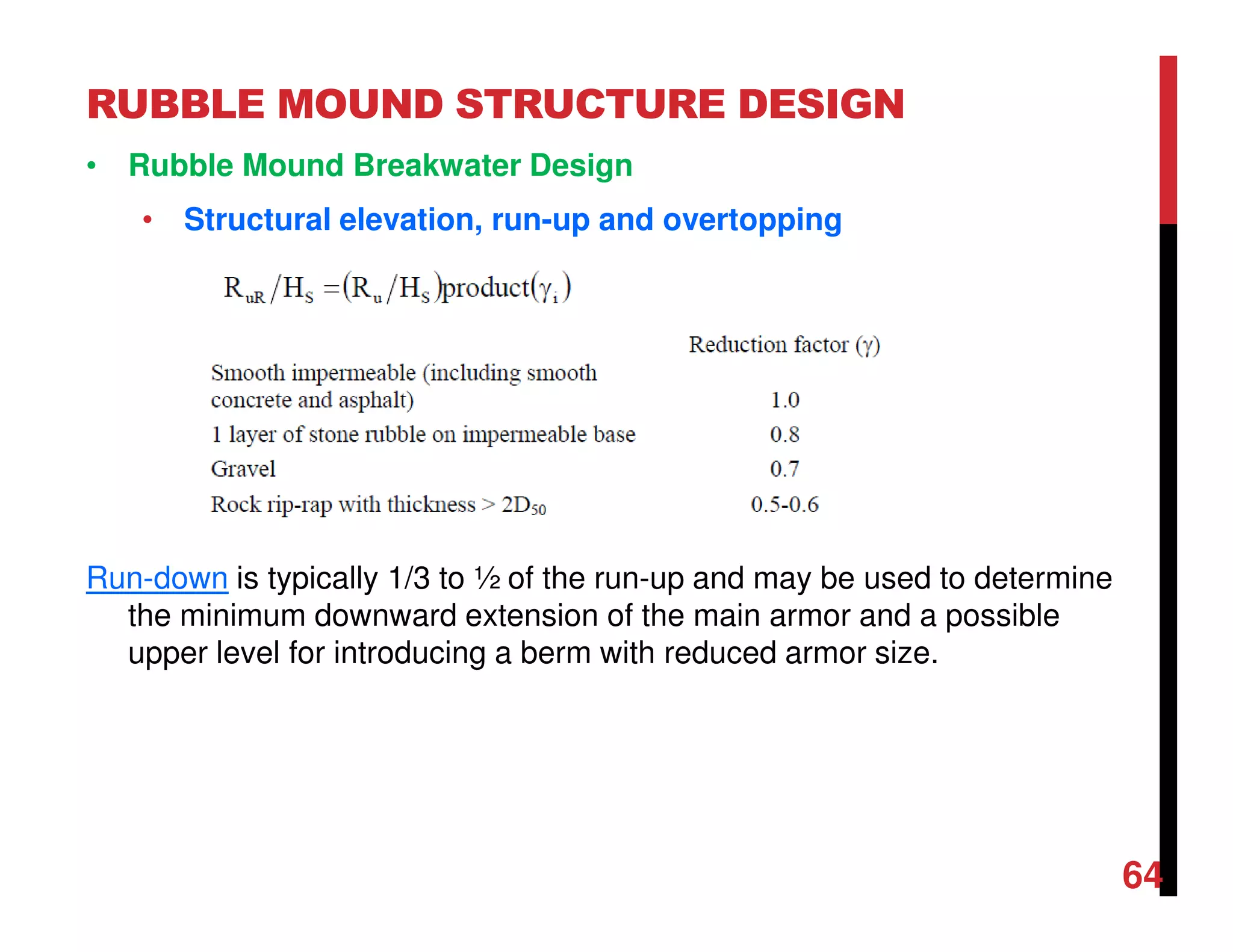
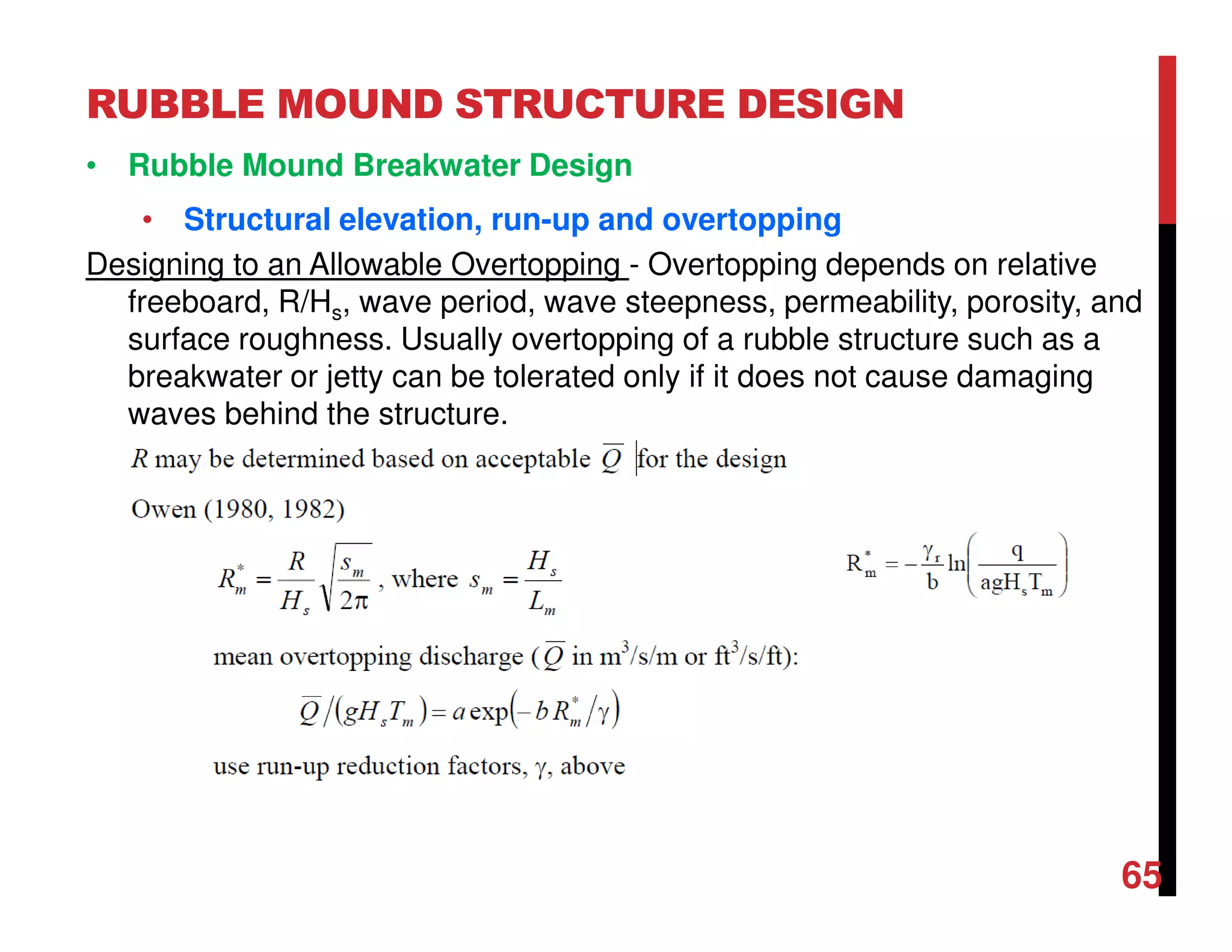
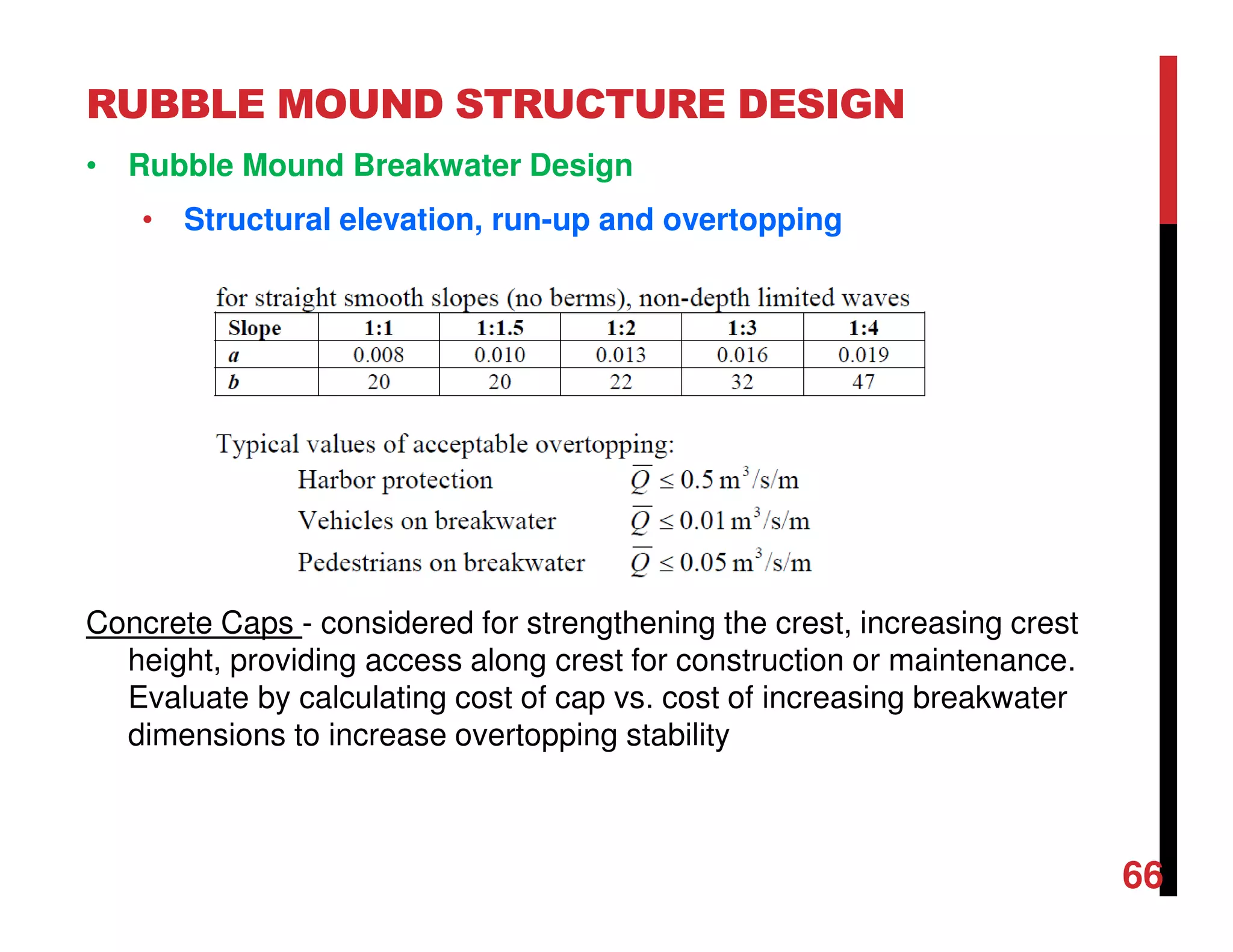
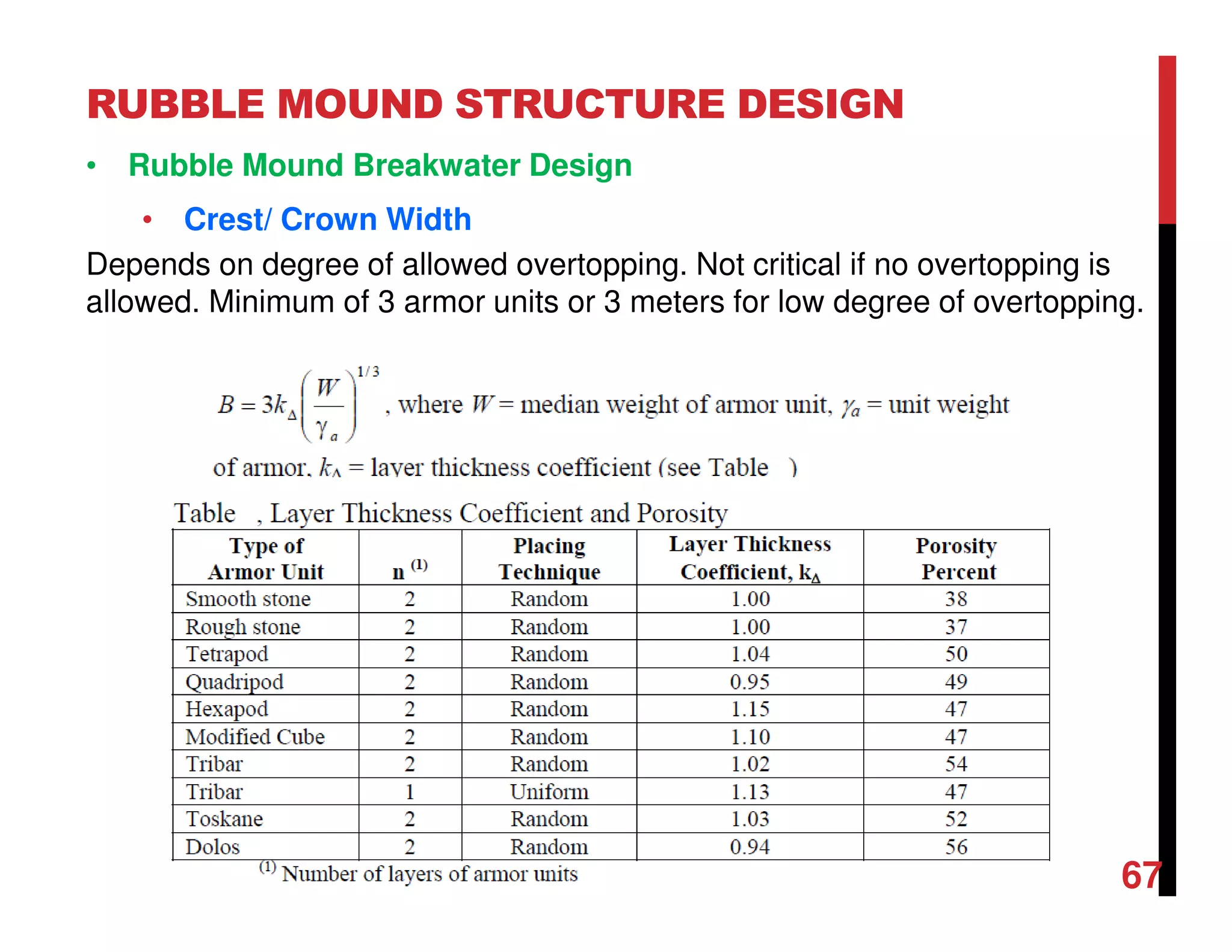
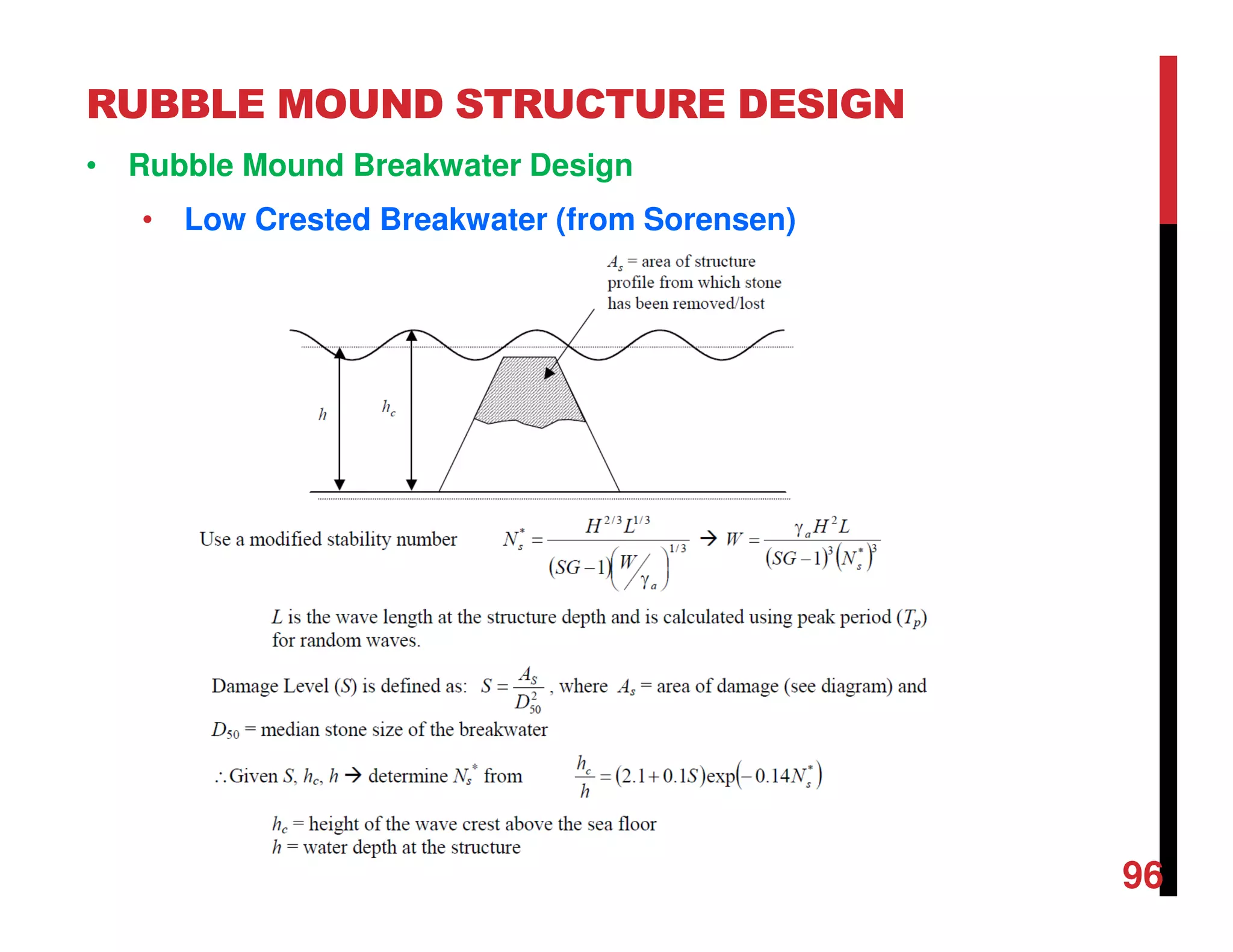
• Rubble Mound Breakwater Design
• Structural elevation, run-up and overtopping
• Overtopping occurs if the freeboard (R) is less than the [set-up + Ru]
• Generally neglect wave setup for sloped structures
• Freeboard may be zero if overtopping is allowed. Freeboard may also be
set to achieve a given allowed overtopping.
• Run-up and run-down are functions of surf similarity parameter, ξ,
permeability, porosity and surface roughness of the slope.
• Effects of Permeability - Flow fields induced in permeable structures by
wave action result in reduced run-up and run-down, but increased
destabilizing forces (see diagram).](https://image.slidesharecdn.com/chapter5coastalstructures-180204113034/75/Chapter-5-coastal-structures-62-2048.jpg)
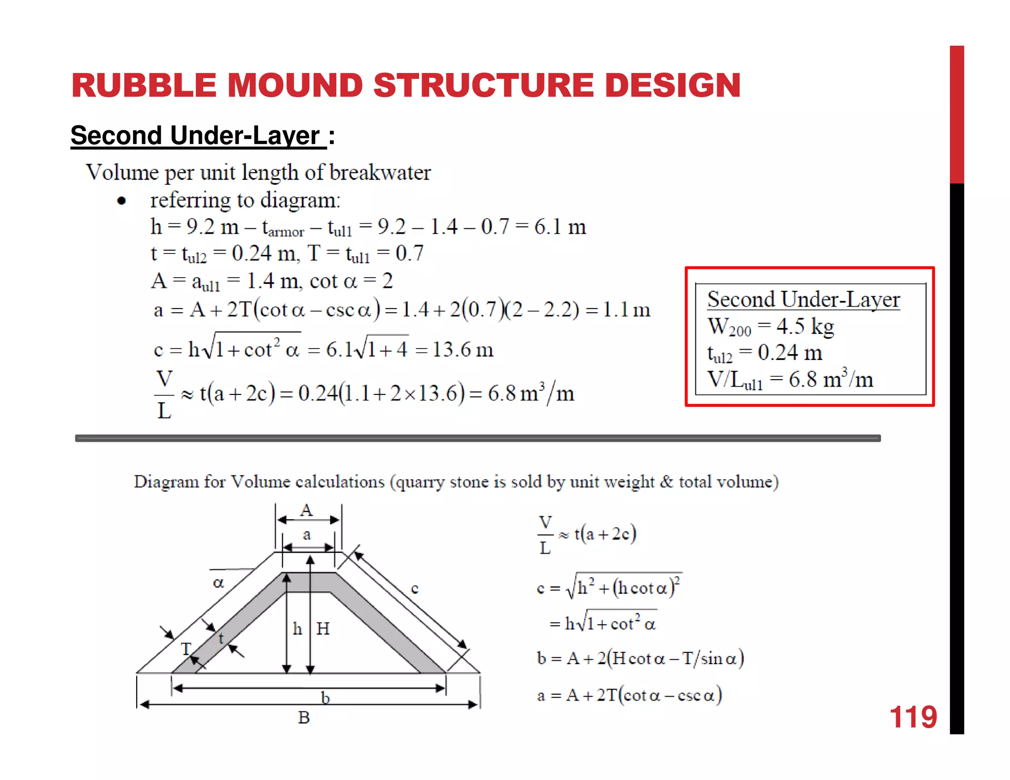
![RUBBLE MOUND STRUCTURE DESIGN
101
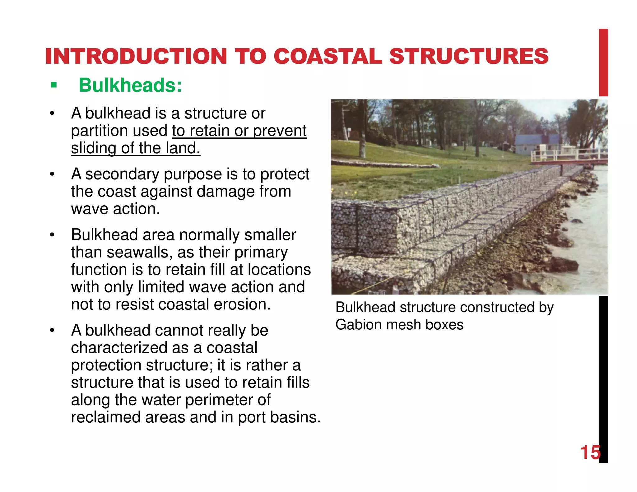
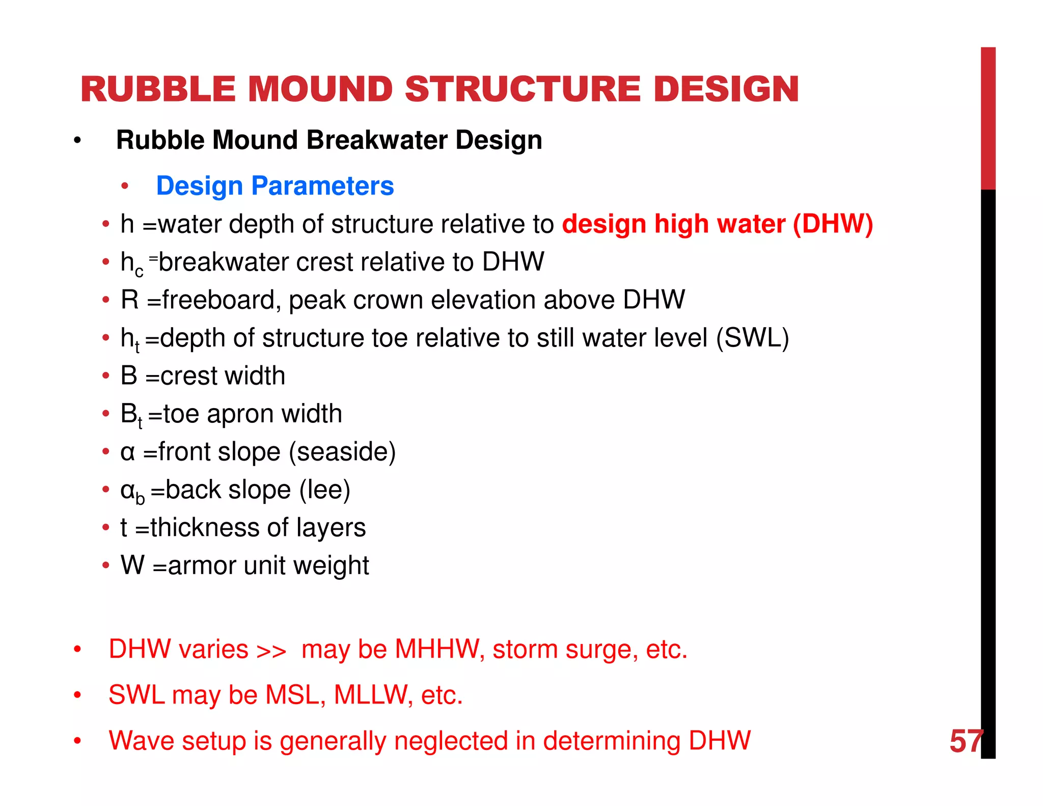
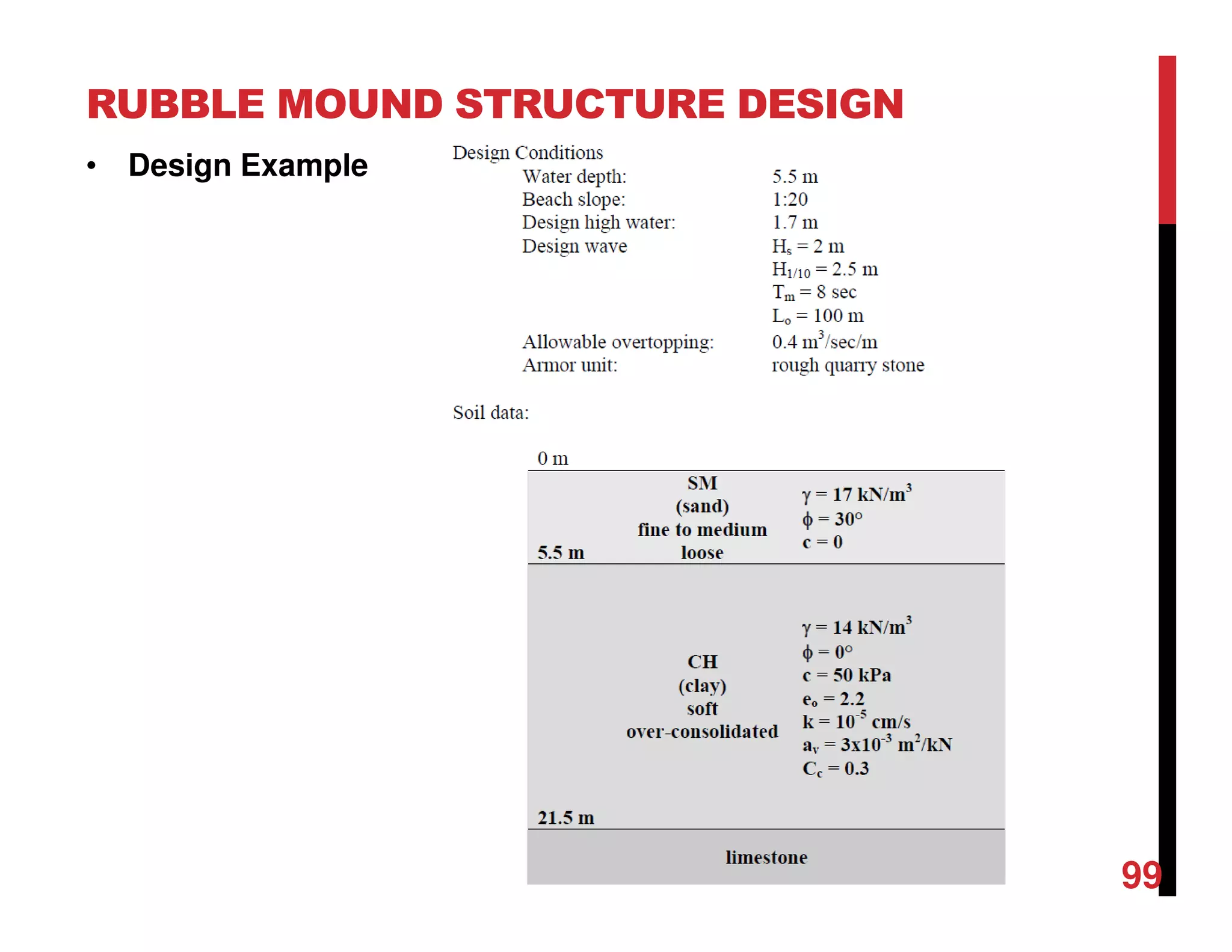
Specify Design Condition
Still water level (SWL) = 5.5 m,
Design high water (DHW) = 1.7 m
Water depth h (or d) = 5.5 + 1.7 = 7.2m
Assume listed conditions are at structure toe.
Hs = H1/3 = 2 m
T = 8 sec
Lo = 100 m
Using dispersion relation, calculate L at h =7.2m [take d=h]
Lm=62m](https://image.slidesharecdn.com/chapter5coastalstructures-180204113034/75/Chapter-5-coastal-structures-101-2048.jpg)
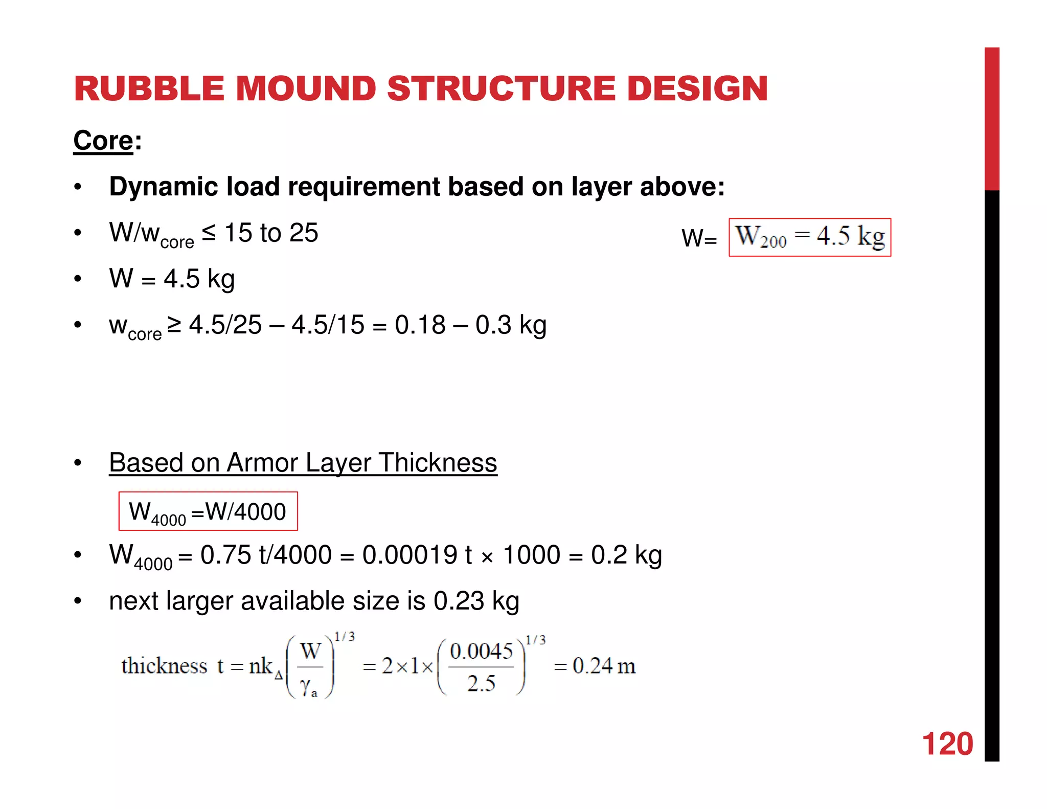
![RUBBLE MOUND STRUCTURE DESIGN
10
2
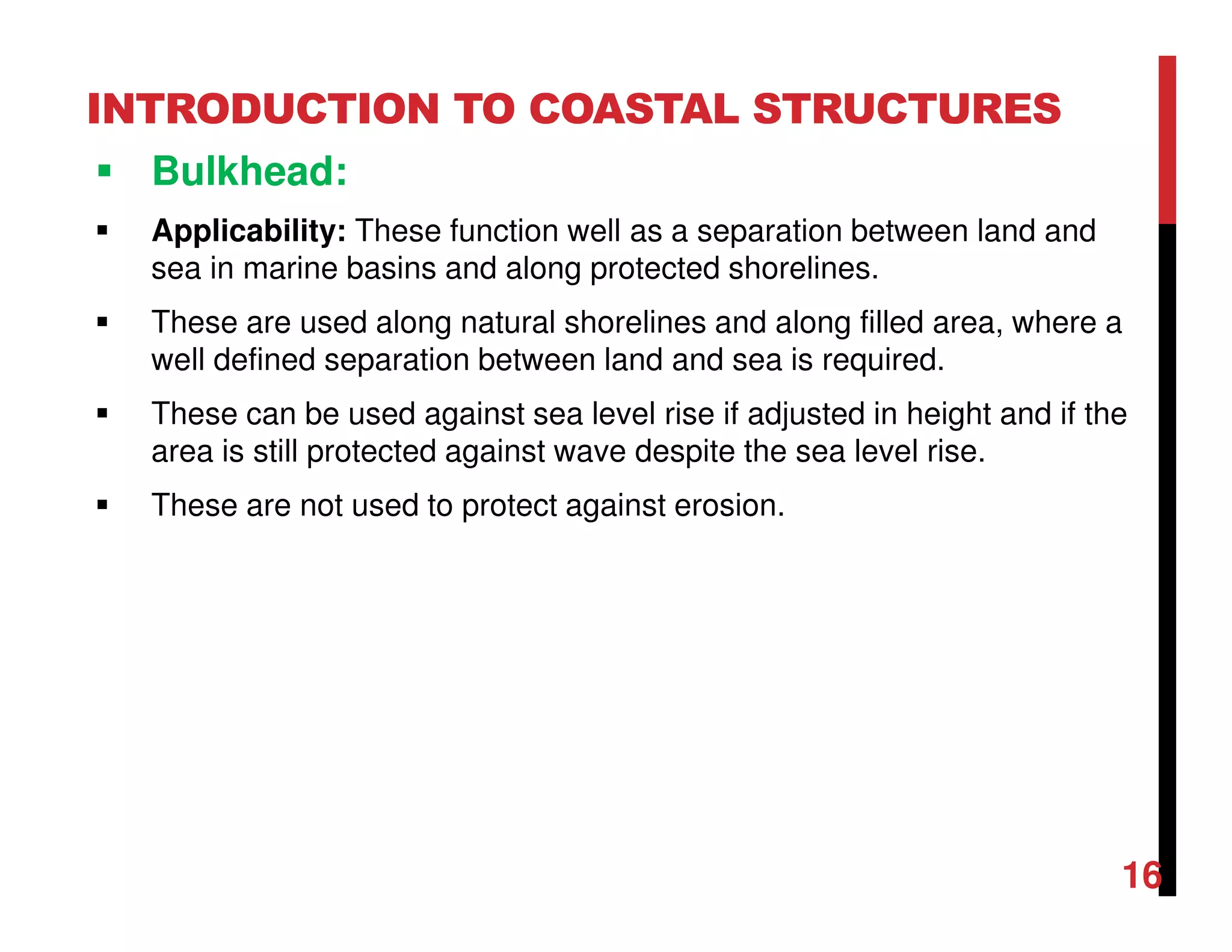
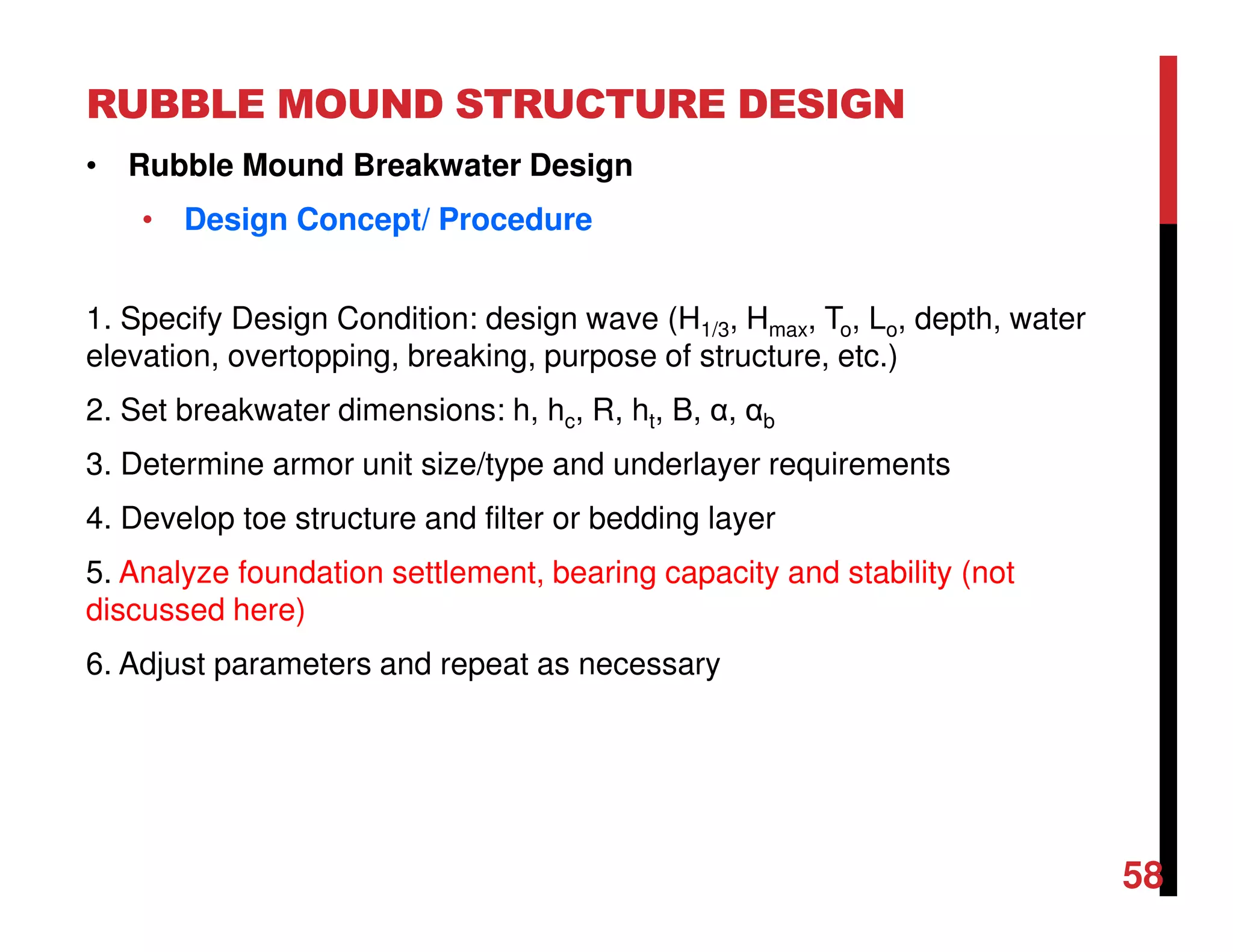
Specify Design Condition
Calculate depth limited breaking wave height at structure toe, compare with
unbroken wave height and use less of the two for design
Hb/hb ~ 0.78** [simplified breaking criteria]
at DHW: Hb = 0.78×7.2 = 5.6 m [hb=db]
at SWL: Hb = 0.78×5.5 = 4.3 m
**Alternative breaking methods may be applied.
Both waves heights are greater than Hs which means waves are not
breaking and design H=Hs=2m](https://image.slidesharecdn.com/chapter5coastalstructures-180204113034/75/Chapter-5-coastal-structures-102-2048.jpg)


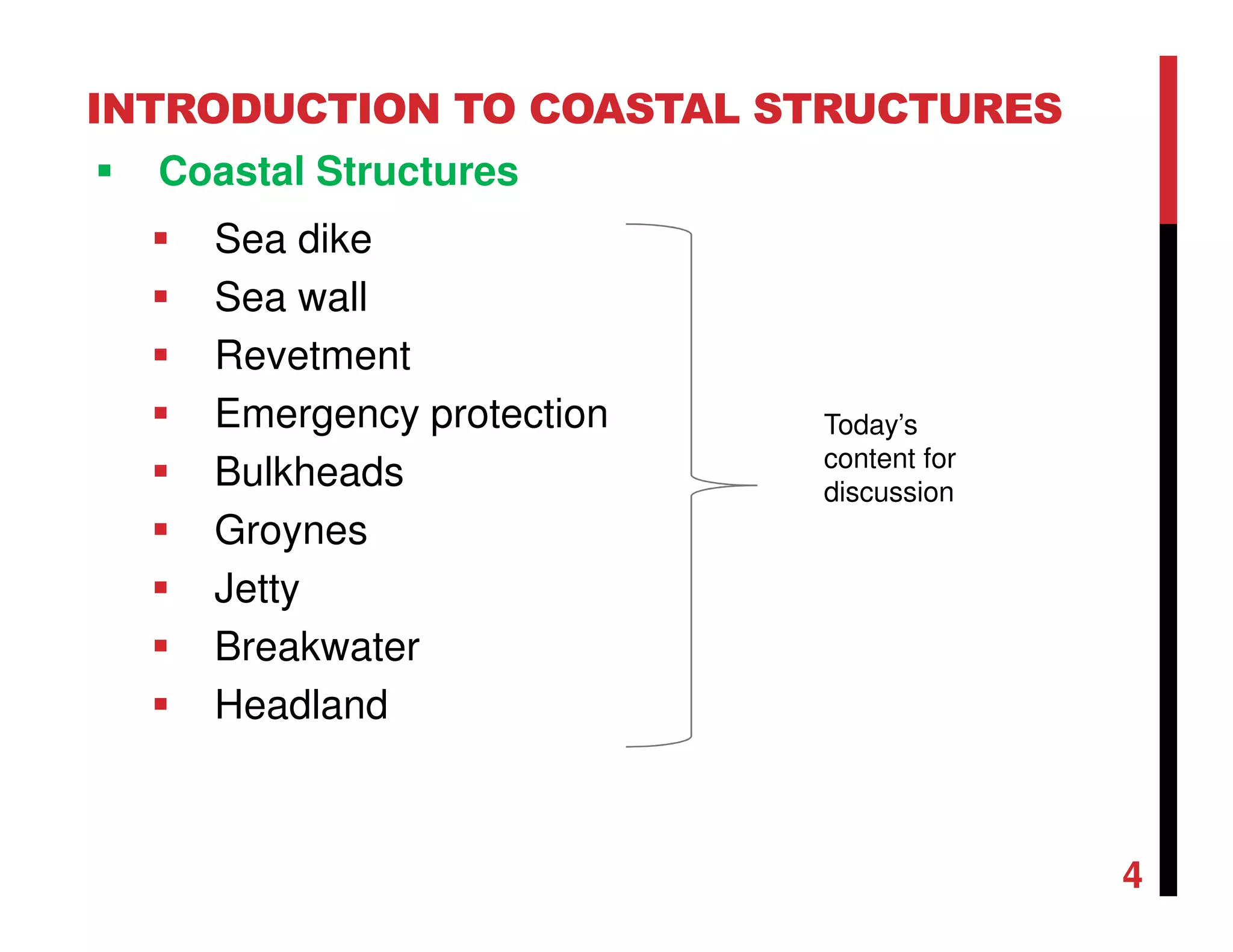
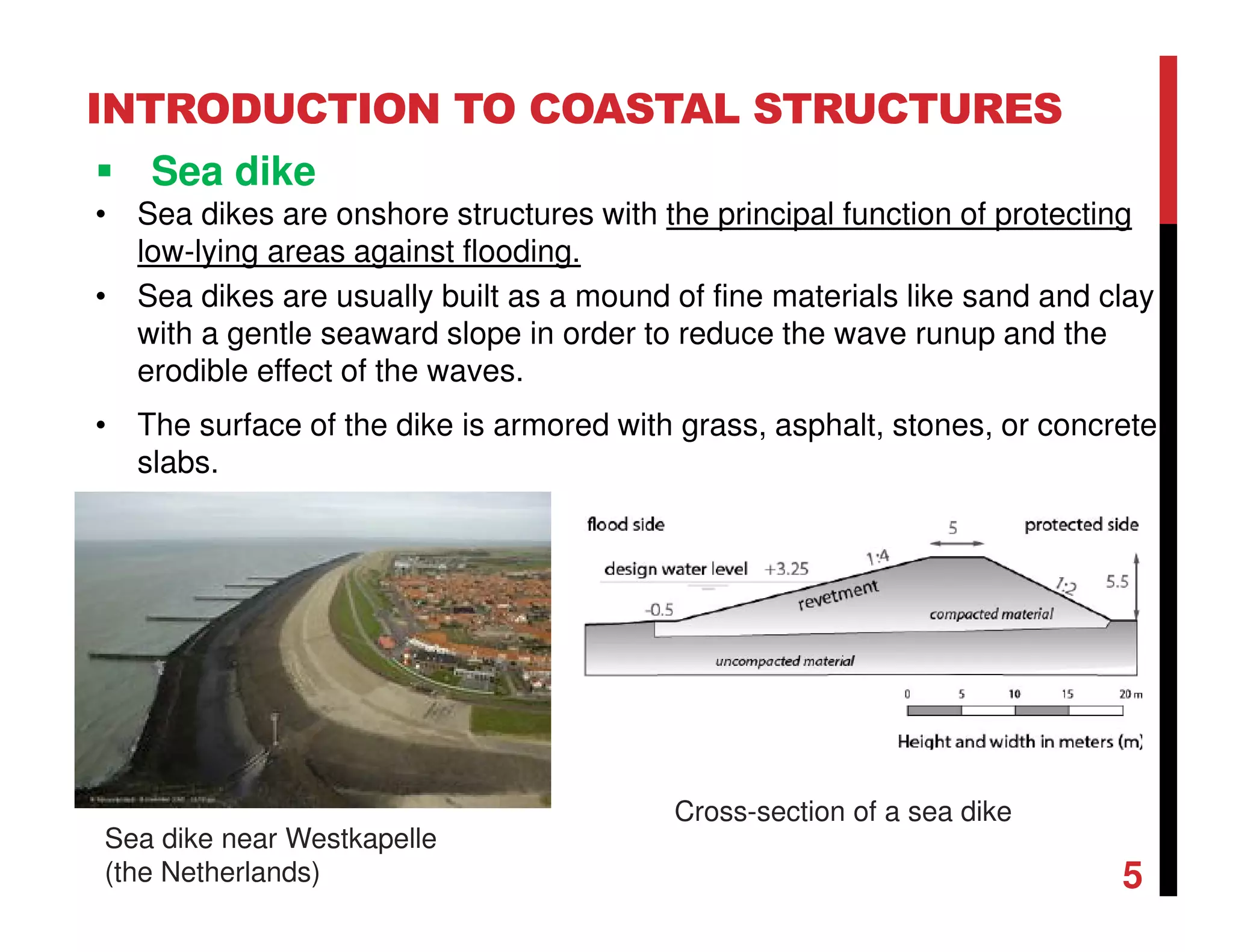
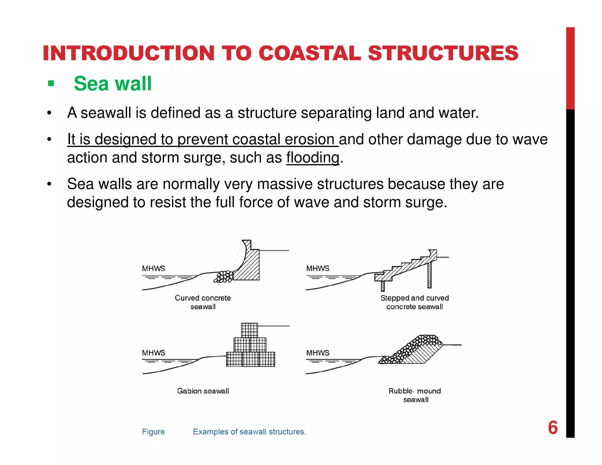
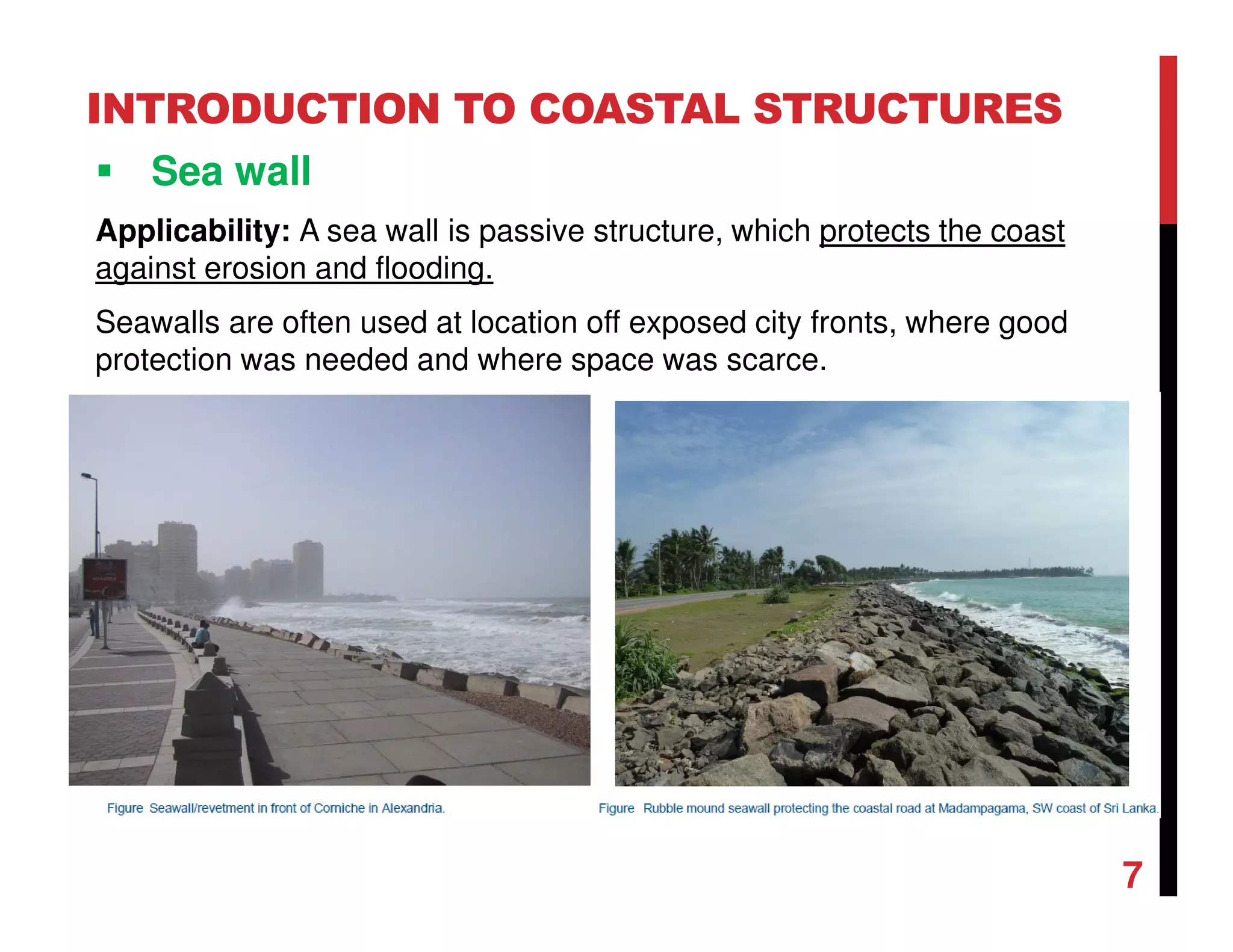
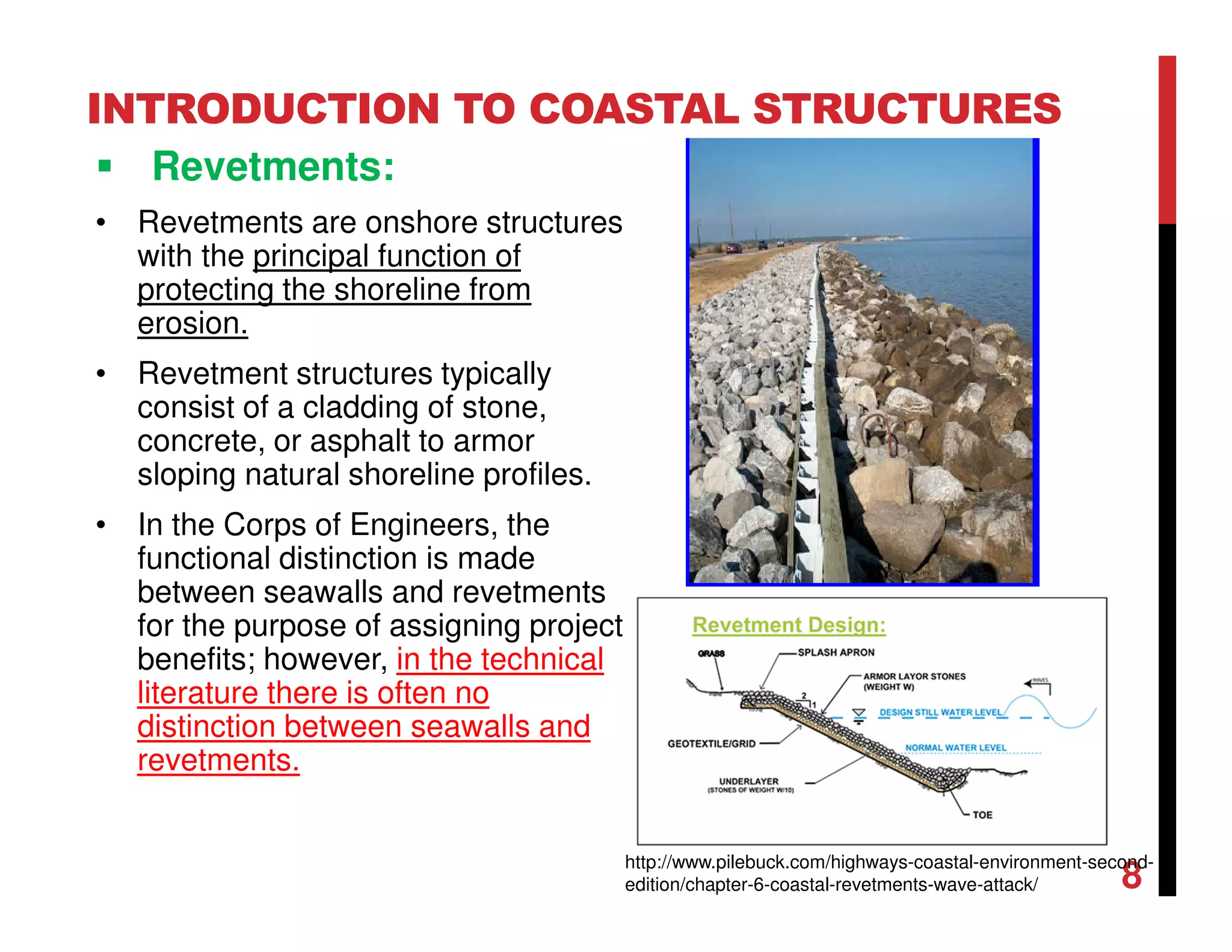
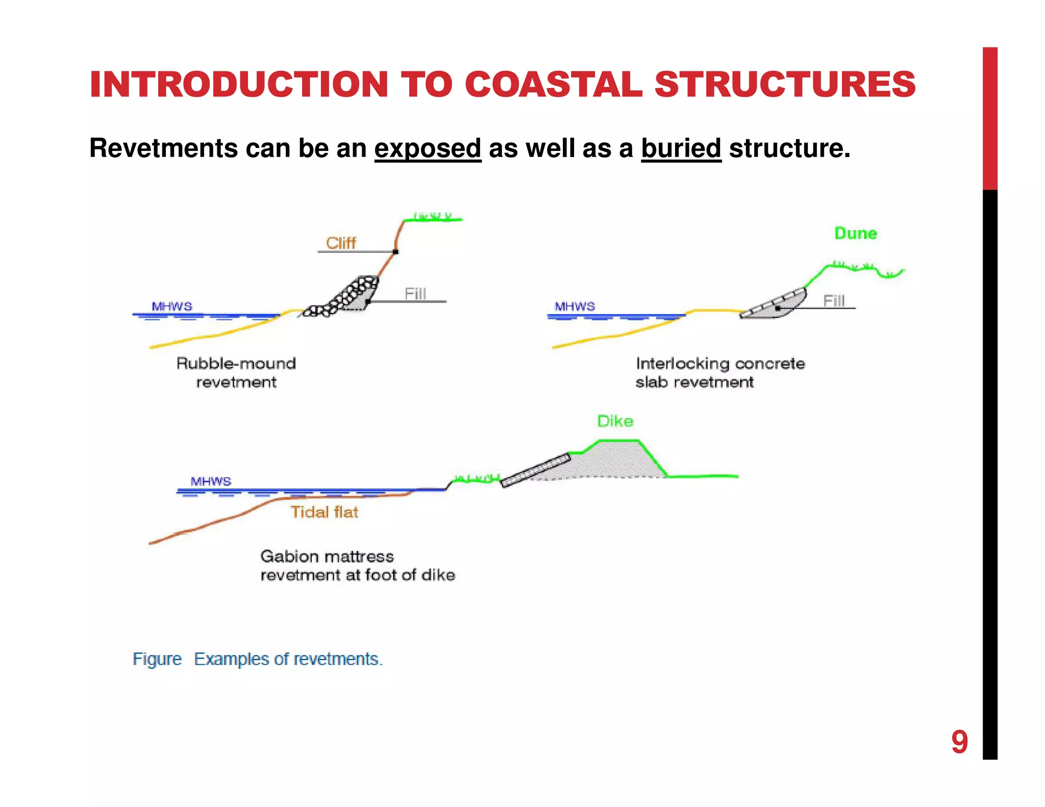
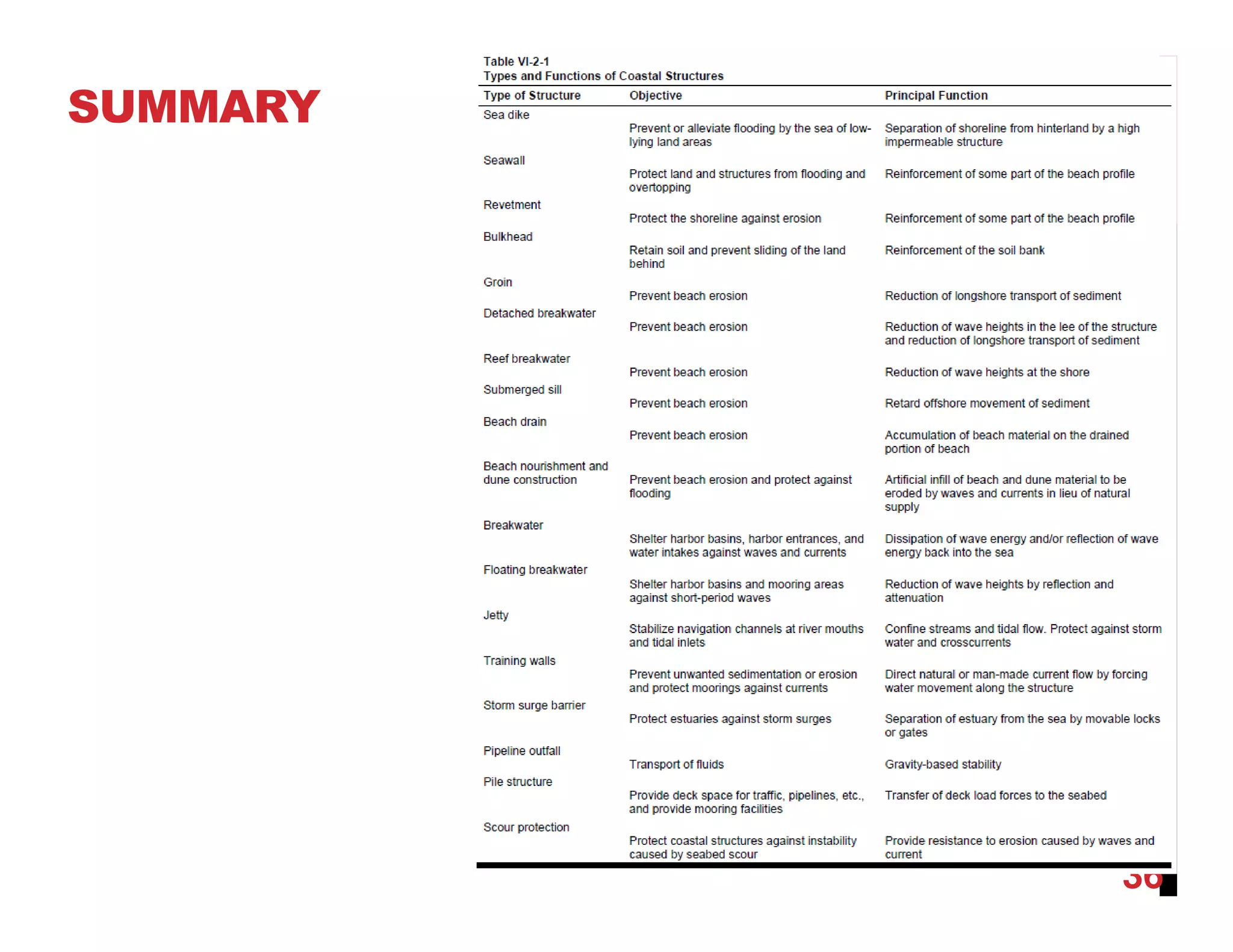
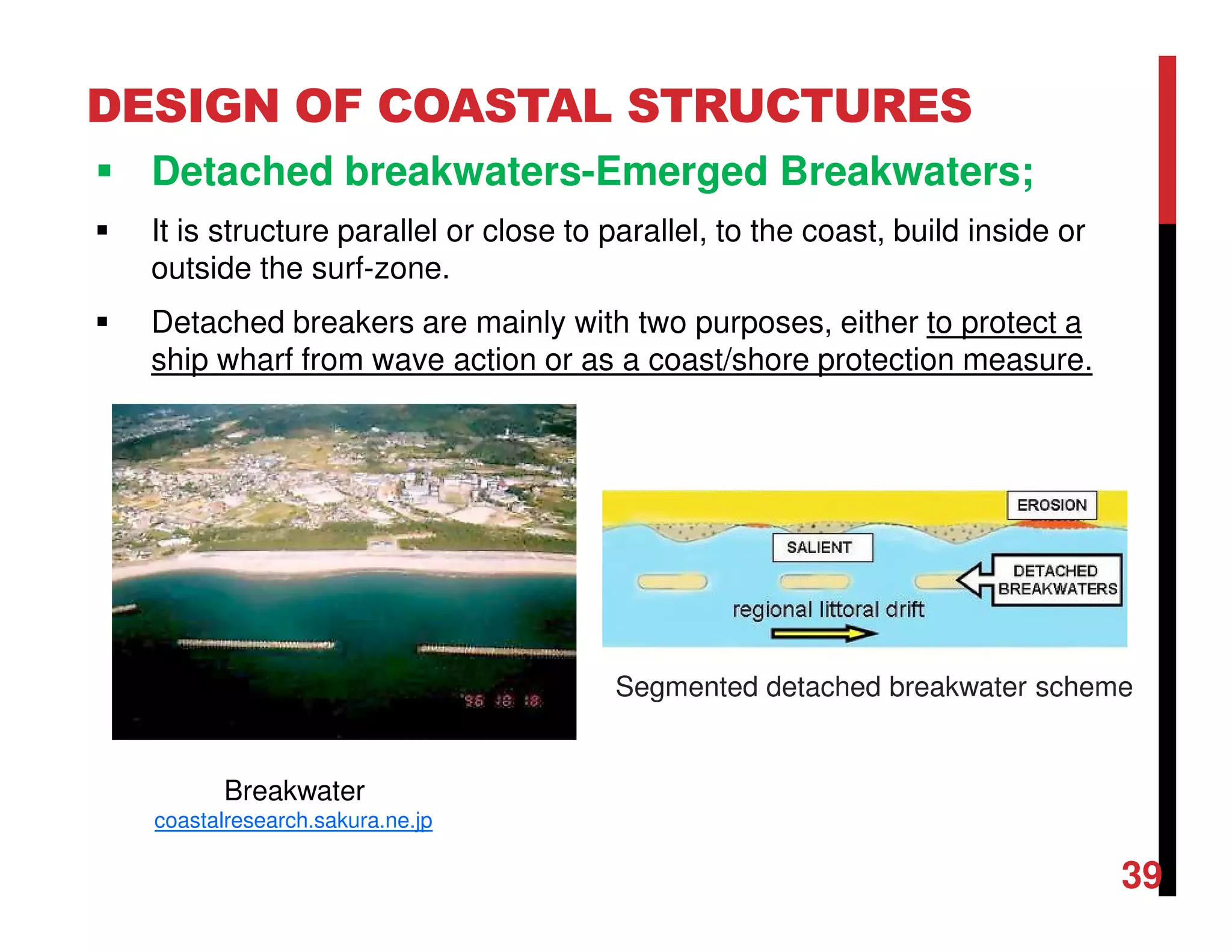
The document provides an introduction to various coastal structures used for coastal protection. It describes sea dikes, sea walls, revetments, emergency protection, bulkheads, groynes, jetties, breakwaters, and detached breakwaters. Each coastal structure is defined and its applicability is discussed. The document categorizes coastal protection structures as coastal protection, shore protection, beach construction, management solutions, and sea defense. It aims to give an overview of different types of structures used to protect coasts from erosion, flooding, and damage from waves and currents.


![Engineering Economics: Solved exam problems [ch1-ch4]](https://cdn.slidesharecdn.com/ss_thumbnails/solvedexamproblemsch1-ch4-200220070043-thumbnail.jpg?width=640&height=640&fit=bounds)