Download as PDF, PPTX


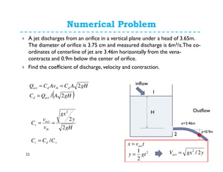


![Discharge over Triangular Notch (V-Notch)
37
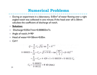
In order to obtain discharge over
whole area we must integrate above
equation from h=0 to h=H, therefore;
( )[ ]2/5
2/tan2
15
8
HgCQ dact θ=](https://image.slidesharecdn.com/flowmeasurement-150316030307-conversion-gate01/85/Flow-measurement-37-320.jpg)


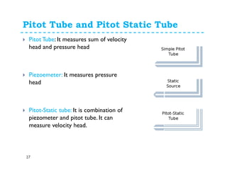
![Discharge over Triangular Notch (V-Notch)
44
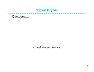
In order to obtain discharge over
whole area we must integrate above
equation from h=0 to h=H, therefore;
( ) ( )( )( )
( ) ( ) dhhhHgQ
ghhHdhQ
H
H
∫
∫
−=
−=
0
0
2/tan22
22/tan2
θ
θ
( ) ( )
( )
=
−= ∫
2/5
0
2/32/1
15
4
2/tan22
2/tan22
HgQ
dhhHhgQ
H
θ
θ
( )[ ]2/5
2/tan2
15
8
HgQ θ=
( )[ ]2/5
2/tan2
15
8
HgCQ dact θ=](https://image.slidesharecdn.com/flowmeasurement-150316030307-conversion-gate01/85/Flow-measurement-44-320.jpg)

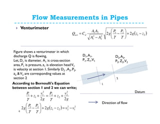
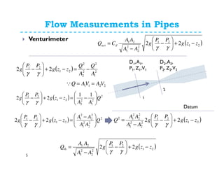
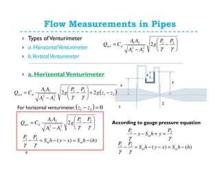
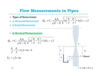
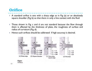
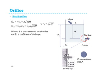
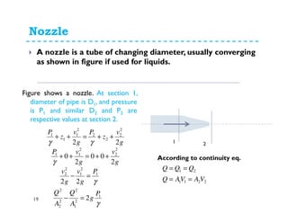
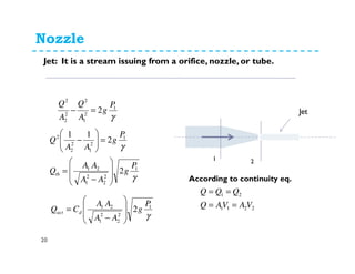
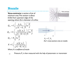
This document discusses various flow measurement techniques including venturimeters, orifices, mouthpieces, pitot tubes, weirs and notches. It provides detailed explanations and equations for venturimeters and orifices. Venturimeters use the Bernoulli's equation to relate the pressure difference between two sections to the flow rate. Orifices use the relationship between head loss and flow rate. The document also defines various coefficients used in flow measurements like coefficient of contraction, velocity, and discharge. It discusses types of venturimeters and orifices based on their orientation and geometry.


![Engineering Economics: Solved exam problems [ch1-ch4]](https://cdn.slidesharecdn.com/ss_thumbnails/solvedexamproblemsch1-ch4-200220070043-thumbnail.jpg?width=640&height=640&fit=bounds)