Download as PDF, PPTX
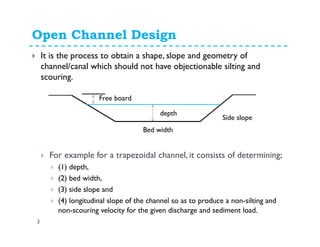
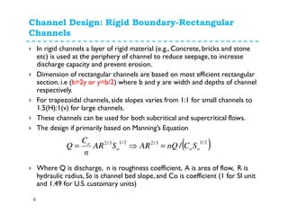
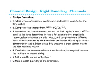
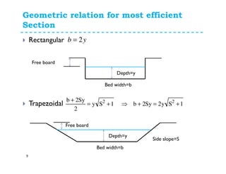
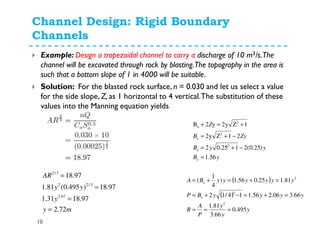
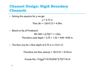
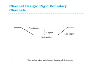

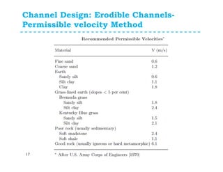
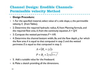
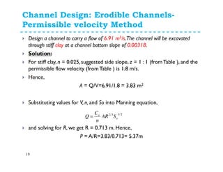
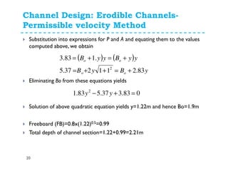
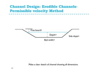
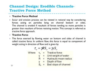
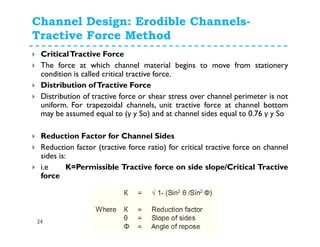
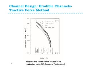

The document discusses open channel design for both rigid boundary and erodible channels. It describes the key steps in designing trapezoidal channels including determining depth, bed width, side slopes, and longitudinal slope. For rigid boundary channels, the most common design approach is to use Manning's equation to select dimensions that produce non-silting, non-scouring velocities. For erodible channels, two common methods are discussed: the permissible velocity method, which ensures the mean flow velocity is below erosion thresholds; and the tractive force method, which involves equating tractive forces to critical shear stresses of the channel material.


![Engineering Economics: Solved exam problems [ch1-ch4]](https://cdn.slidesharecdn.com/ss_thumbnails/solvedexamproblemsch1-ch4-200220070043-thumbnail.jpg?width=640&height=640&fit=bounds)