Downloaded 700 times

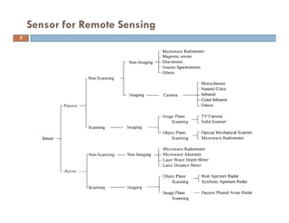
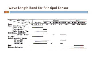


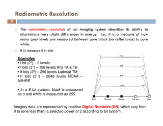
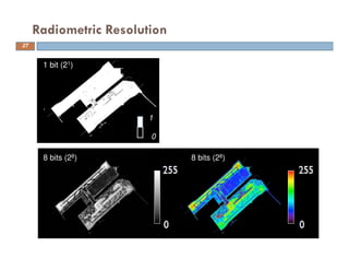


This document discusses remote sensing and geographical information systems in civil engineering. It covers various topics related to remote sensing sensors including optical sensors, thermal scanners, multispectral sensors, passive and active sensors, scanning and non-scanning sensors, imaging and non-imaging sensors, and the different types of resolutions including spatial, spectral, radiometric, and temporal resolution. It provides examples and illustrations of these concepts.


![Engineering Economics: Solved exam problems [ch1-ch4]](https://cdn.slidesharecdn.com/ss_thumbnails/solvedexamproblemsch1-ch4-200220070043-thumbnail.jpg?width=640&height=640&fit=bounds)