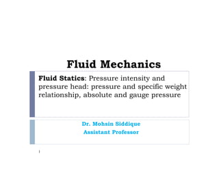
Download as PDF, PPTX


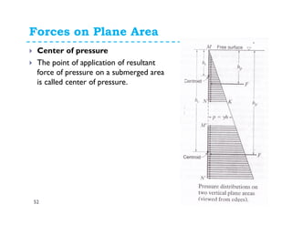


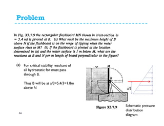


![Buoyancy and Floatation
74
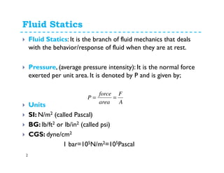
Lets consider a body
submerged in water as shown
in figure.
The force of buoyancy
“resultant upward force or
thrust exerted by fluid on
submerged body” is given
Water surface
11 hP γ=
( )212 hhP += γ
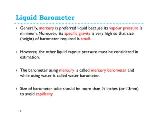
2h
1h 1F
2F
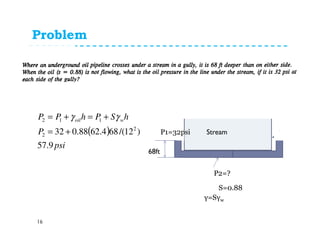
dA=Area of cross-section of
element
γ= Specific weight of liquid
( ) ( )
( )[ ]
[ ]volumeF
dAhF
dAhdAhhF
FFF
B
B
B
B
γ
γ
γγ
=
=
−+=
−=
2
121
12](https://image.slidesharecdn.com/fluidstatics-150316025622-conversion-gate01/85/Fluid-statics-74-320.jpg)
![Buoyancy and Floatation
75
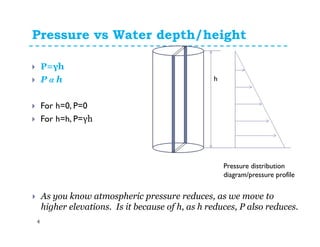
=Weight of volume of liquid displaced by
the body (Archimedes's Principle)
Force of buoyancy can also be determined as difference of
weight of a body in air and in liquid.
Let
Wa= weight of body in air
Wl=weight of body in liquid
FB=Wa-Wl
[ ]volumeFB γ=](https://image.slidesharecdn.com/fluidstatics-150316025622-conversion-gate01/85/Fluid-statics-75-320.jpg)


This document discusses fluid statics and pressure measurement. It defines concepts like absolute pressure, gauge pressure, atmospheric pressure, and Pascal's law. It describes devices used to measure pressure like manometers, piezometers, and Bourdon gauges. Specifically, it provides details on how liquid manometers and differential manometers work, including the principles, setup, and equations to calculate pressure. It also lists the advantages and limitations of using manometers for pressure measurement applications.


![Engineering Economics: Solved exam problems [ch1-ch4]](https://cdn.slidesharecdn.com/ss_thumbnails/solvedexamproblemsch1-ch4-200220070043-thumbnail.jpg?width=640&height=640&fit=bounds)