Download as PDF, PPTX
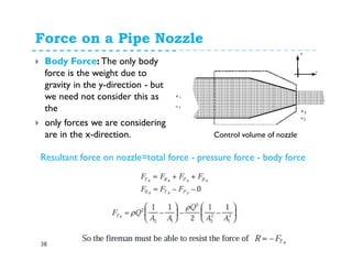
![Equation of forced vortex flow
10
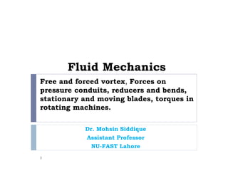
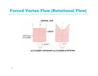
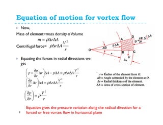
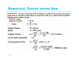
For forced vortex flow, we have;
Where ω is angular velocity=constt
Substituting the values ofV in equation of motion
of vortex flow
Consider two points 1 and 2 in the fluid having
forced vortex and integrating above equation for
point 1 and point 2, we get
rV ×= ω
gdzdr
r
r
p ρ
ω
ρ −=∂
22
∫∫∫ −=
2
1
2
1
2
2
1
gdzdrrpd ρρω
[ ] [ ]12
2
1
2
2
2
12
2
zzgrrpp −−−=− ρ
ρω
60
2 Nπ
ω =](https://image.slidesharecdn.com/vortexflowandimpulsemomentum-150316030613-conversion-gate01/85/Fluid-MechanicsVortex-flow-and-impulse-momentum-10-320.jpg)
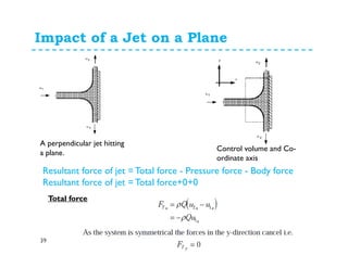
![Equation of forced vortex flow
11
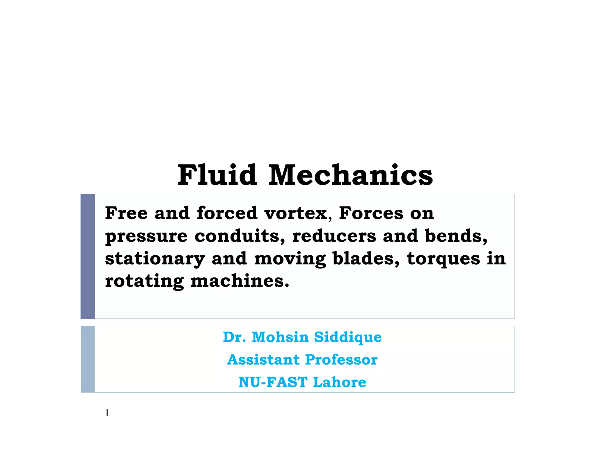
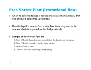
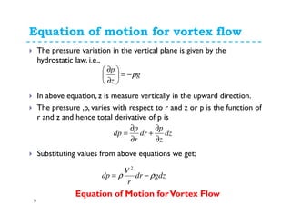
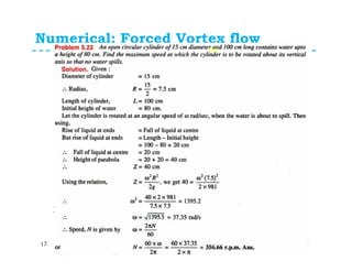
If the point 1 and 2 lie on the free surface then,
p1=p2=Patm=0 and hence above equation become;
[ ] [ ]
1122
12
2
1
22
2
2
12
&
2
rVrV
zzgrrpp
ωω
ρωω
ρ
==
−−−=−
Q
[ ] [ ]12
2
1
2
212
2
zzgVVpp −−−=− ρ
ρ
[ ]
[ ] [ ]2
1
2
212
2
1
2
2
2
1
2
0
VV
g
zz
gVV
−=−
−−= ρ
ρ](https://image.slidesharecdn.com/vortexflowandimpulsemomentum-150316030613-conversion-gate01/85/Fluid-MechanicsVortex-flow-and-impulse-momentum-11-320.jpg)
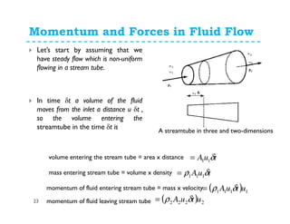
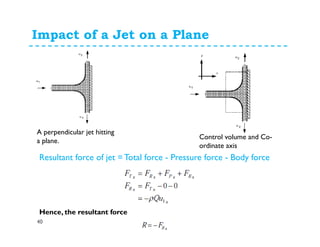
![Equation of forced vortex flow
12
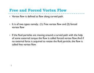
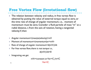
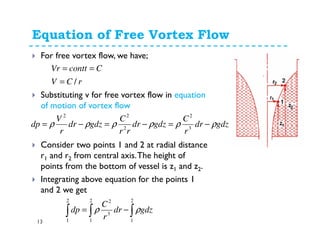
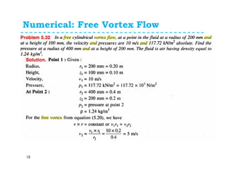
If the point 1 lie on axis of rotation then, v1= ω r1=
ω x0=0 and hence above equation becomes;
Thus, Z varies with square of r. Hence, equation is
an equation of parabola.This means the free surface
is paraboloid
[ ] [ ]
[ ] [ ]2
2
22
2
2
212
2
1
2
1
2
1
r
g
V
g
Z
V
g
zz
ω==
=−
[ ] [ ]0212 −=−= zzzZQ](https://image.slidesharecdn.com/vortexflowandimpulsemomentum-150316030613-conversion-gate01/85/Fluid-MechanicsVortex-flow-and-impulse-momentum-12-320.jpg)
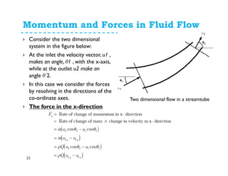
![Equation of Free Vortex Flow
14
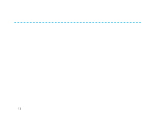
[ ]122
1
2
2
2
12
2
1
2
1
32
2
1
2
1
3
22
1
11
2
zzg
rr
C
pp
gdzdrrcgdzdr
r
C
dp
−−
−−=−
−=−= ∫∫∫∫∫
−
ρ
ρ
ρρρρ
[ ]
[ ] [ ]12
2
1
2
212
122
1
2
2
2
2
12
2
2
zzgVVpp
zzg
r
C
r
C
pp
−−−−=−
−−
−−=−
ρ
ρ
ρ
ρ
[ ] [ ] [ ]
12
2
1
2
212
12
2
1
2
2122
1
2
2
2
2
12
22
22
zz
g
V
g
V
g
p
g
p
zzVV
g
zz
g
g
r
C
r
C
gg
pp
+−+−=−
−−−−=−−
−−=
−
ρρ
ρ
ρ
ρ
ρ
ρ
g
Vp
z
g
Vp
z
22
2
22
2
2
11
1 ++=++
γγ](https://image.slidesharecdn.com/vortexflowandimpulsemomentum-150316030613-conversion-gate01/85/Fluid-MechanicsVortex-flow-and-impulse-momentum-14-320.jpg)

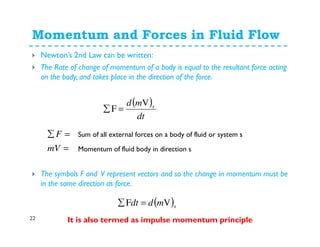
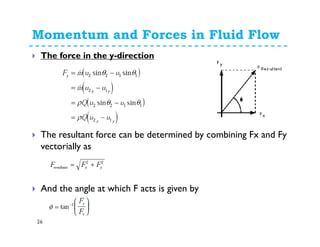
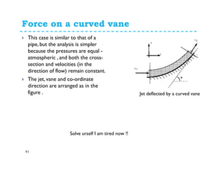
![Momentum and Forces in Fluid Flow
24
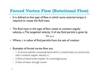
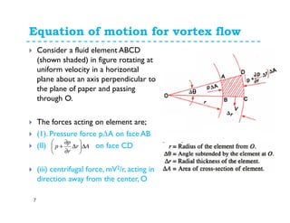
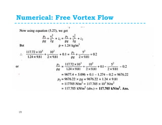
Now, according to Newton’s 2nd Law the force exerted by the fluid
is equal to the rate of change of momentum. So
Force=rate of change of momentum
We know from continuity of incompressible flow, ρ=ρ1= ρ2 &
Q=Q1=Q2
( ) ( ) ( ) ( ) 111222
11112222
1111222211112222
F
F
uQuQ
t
utuA
t
utuA
t
tuuA
t
tuuA
t
tuuAtuuA
ρρ
δ
δρ
δ
δρ
δ
δρ
δ
δρ
δ
δρδρ
−=−=∑
−=
−
=∑
[ ] [ ]1212 uumuuQF −=−= ρ
This analysis assumed that the inlet and outlet velocities were in the
same direction - i.e. a one dimensional system.What happens when
this is not the case?](https://image.slidesharecdn.com/vortexflowandimpulsemomentum-150316030613-conversion-gate01/85/Fluid-MechanicsVortex-flow-and-impulse-momentum-24-320.jpg)
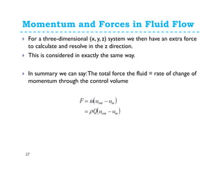
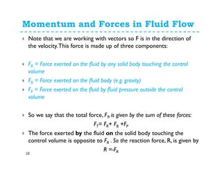
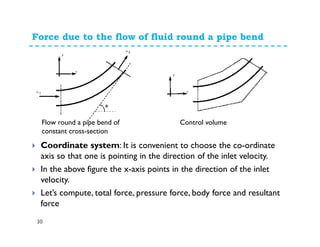
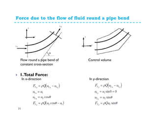
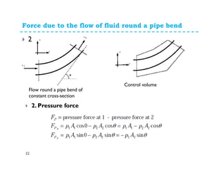
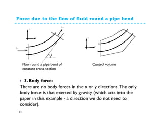
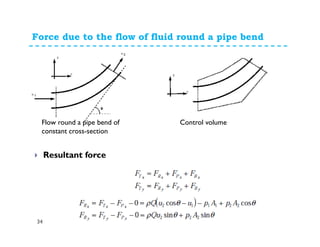
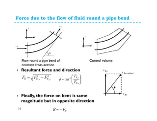
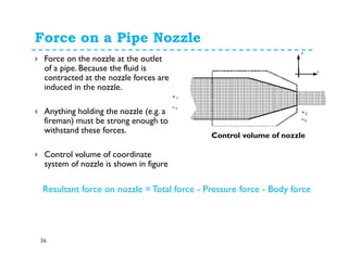
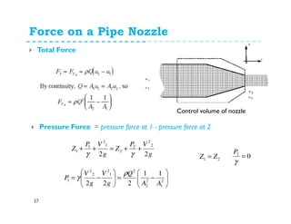


1. The momentum equation relates the total force on a fluid system to the rate of change of momentum as fluid flows through a control volume. 2. Forces can be resolved into components in different directions for multi-dimensional flows. The total force is equal to the sum of pressure, body, and reaction forces. 3. Examples of applying the momentum equation include calculating forces on a pipe bend, nozzle, jet impact, and curved vane due to changing fluid momentum. Setting up coordinate systems aligned with the flow is important for resolving forces into components.


![Engineering Economics: Solved exam problems [ch1-ch4]](https://cdn.slidesharecdn.com/ss_thumbnails/solvedexamproblemsch1-ch4-200220070043-thumbnail.jpg?width=640&height=640&fit=bounds)