The 2007 ASME Boiler and Pressure Vessel Code outlines qualifications for welding and brazing procedures, including rules for construction, materials specifications, and examination standards necessary for different components and applications. It establishes procedures for public review and input while clarifying that ASME doesn't endorse any items or assume liability regarding patent rights. The code is revised periodically, and interpretations are provided to aid users in understanding technical aspects.


![2007 SECTION IX
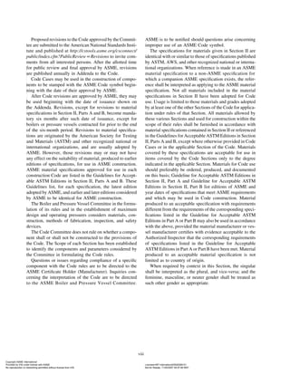
performance qualification as permitted in QW-305 to prove
the ability of welding operators to make sound welds.
QW-144 Visual Examination
Visual examination as described in QW-194 is used to
determine that the final weld surfaces meet specified quality
conditions.
QW-150 TENSION TESTS
QW-151 Specimens
Tension test specimens shall conform to one of the types
illustrated in figures QW-462.1(a) through QW-462.1(e)
and shall meet the requirements of QW-153.
QW-151.1 Reduced Section — Plate. Reduced-sec-
tion specimens conforming to the requirements given in
figure QW-462.1(a) may be used for tension tests on all
thicknesses of plate.
(a) For thicknesses up to and including 1 in. (25 mm),
a full thickness specimen shall be used for each required
tension test.
(b) For plate thickness greater than 1 in. (25 mm), full
thickness specimens or multiple specimens may be used,
provided QW-151.1(c) and QW-151.1(d) are complied
with.
(c) When multiple specimens are used, in lieu of full
thickness specimens, each set shall represent a single ten-
sion test of the full plate thickness. Collectively, all of the
specimens required to represent the full thickness of the
weld at one location shall comprise a set.
(d) When multiple specimens are necessary, the entire
thickness shall be mechanically cut into a minimum num-
ber of approximately equal strips of a size that can be
tested in the available equipment. Each specimen of the
set shall be tested and meet the requirements of QW-153.
QW-151.2 Reduced Section — Pipe. Reduced-section
specimens conforming to the requirements given in figure
QW-462.1(b) may be used for tension tests on all thick-
nesses of pipe having an outside diameter greater than 3 in.
(75 mm).
(a) For thicknesses up to and including 1 in. (25 mm),
a full thickness specimen shall be used for each required
tension test.
(b) For pipe thicknesses greater than 1 in. (25 mm), full
thickness specimens or multiple specimens may be used,
provided QW-151.2(c) and QW-151.2(d) are complied
with.
(c) When multiple specimens are used, in lieu of full
thickness specimens, each set shall represent a single ten-
sion test of the full pipe thickness. Collectively, all of the
specimens required to represent the full thickness of the
weld at one location shall comprise a set.
4
(d) When multiple specimens are necessary, the entire
thickness shall be mechanically cut into a minimum num-
ber of approximately equal strips of a size that can be
tested in the available equipment. Each specimen of the
set shall be tested and meet the requirements of QW-153.
For pipe having an outside diameter of 3 in. (75 mm)
or less, reduced-section specimens conforming to the
requirements given in figure QW-462.1(c) may be used
for tension tests.
QW-151.3 Turned Specimens. Turned specimens con-
forming to the requirements given in figure QW-462.1(d)
may be used for tension tests.
(a) For thicknesses up to and including 1 in. (25 mm),
a single turned specimen may be used for each required
tension test, which shall be a specimen of the largest diame-
ter D of figure QW-462.1(d) possible for test coupon thick-
ness [per Note (a) of figure QW-462.1(d)].
(b) For thicknesses over 1 in. (25 mm), multiple speci-
mens shall be cut through the full thickness of the weld
with their centers parallel to the metal surface and not over
1 in. (25 mm) apart. The centers of the specimens adjacent
to the metal surfaces shall not exceed 5
⁄8 in. (16 mm) from
the surface.
(c) When multiple specimens are used, each set shall
represent a single required tension test. Collectively, all
the specimens required to represent the full thickness of
the weld at one location shall comprise a set.
(d) Each specimen of the set shall be tested and meet
the requirements of QW-153.
QW-151.4 Full-Section Specimens for Pipe. Tension
specimens conforming to the dimensions given in figure
QW-462.1(e) may be used for testing pipe with an outside
diameter of 3 in. (75 mm) or less.
QW-152 Tension Test Procedure
The tension test specimen shall be ruptured under tensile
load. The tensile strength shall be computed by dividing
the ultimate total load by the least cross-sectional area of
the specimen as calculated from actual measurements made
before the load is applied.
QW-153 Acceptance Criteria — Tension Tests
QW-153.1 Tensile Strength. Minimum values for pro-
cedure qualification are provided under the column heading
“Minimum Specified Tensile, ksi” of table QW/QB-422.
In order to pass the tension test, the specimen shall have
a tensile strength that is not less than
(a) the minimum specified tensile strength of the base
metal; or
(b) the minimum specified tensile strength of the weaker
of the two, if base metals of different minimum tensile
strengths are used; or
Copyright ASME International
Provided by IHS under license with ASME Licensee=BP International/5928366101
Not for Resale, 11/20/2007 04:57:06 MST
No reproduction or networking permitted without license from IHS
--`,,,,`,`,`,``,,,`,``,````,,```-`-`,,`,,`,`,,`---](https://image.slidesharecdn.com/asmeix9-240528141859-21339aac/85/ASME-IX-9-2007-Full-Version-pdf-29-320.jpg)


![2007 SECTION IX
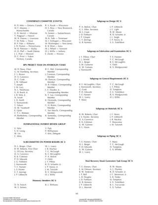
when required, supplementary essential variables. Weld
metal deposited using each set of variables shall be
included in the tension, bend, notch toughness, and other
mechanical test specimens that are required.
(c) Changes to the PQR. Changes to the PQR are not
permitted except as described below. It is a record of
what happened during a particular welding test. Editorial
corrections or addenda to the PQR are permitted. An exam-
ple of an editorial correction is an incorrect P-Number,
F-Number, or A-Number that was assigned to a particular
base metal or filler metal. An example of an addendum
would be a change resulting from a Code change. For
example, Section IX may assign a new F-Number to a
filler metal or adopt a new filler metal under an established
F-Number. This may permit, depending on the particular
construction Code requirements, a manufacturer or con-
tractor to use other filler metals that fall within that particu-
lar F-Number where, prior to the Code revision, the
manufacturer or contractor was limited to the particular
electrode classification that was used during qualification.
Additional information can be incorporated into a PQR at
a later date provided the information is substantiated as
having been part of the original qualification condition by
lab record or similar data.
All changes to a PQR require recertification (including
date) by the manufacturer or contractor.
(d) Format of the PQR. Form QW-483 (see Nonmanda-
tory Appendix B) has been provided as a guide for the
PQR. The information required to be in the PQR may be
in any format to fit the needs of each manufacturer or
contractor, as long as every essential and, when required,
supplementary essential variable, required by QW-250
through QW-280, is included. Also the type of tests, num-
ber of tests, and test results shall be listed in the PQR.
Form QW-483 does not easily lend itself to cover combi-
nations of welding processes or more than one F-Number
filler metal in one test coupon. Additional sketches or
information may be attached or referenced to record the
required variables.
(e) Availability of the PQR. PQRs used to support WPSs
shall be available, upon request, for review by the Author-
ized Inspector (AI). The PQR need not be available to the
welder or welding operator.
(f) Multiple WPSs With One PQR/Multiple PQRs With
One WPS. Several WPSs may be prepared from the data
on a single PQR (e.g., a 1G plate PQR may support WPSs
for the F, V, H, and O positions on plate or pipe within
all other essential variables). A single WPS may cover
several essential variable changes as long as a supporting
PQR exists for each essential and, when required, supple-
mentary essential variable [e.g., a single WPS may cover
a thickness range from 1
⁄16 in. (1.5 mm) through 11
⁄4 in.
(32 mm) if PQRs exist for both the 1
⁄16 in. (1.5 mm) through
14
3
⁄16 in. (5 mm) and 3
⁄16 in. (5 mm) through 11
⁄4 in. (32 mm)
thickness ranges].
QW-200.3 To reduce the number of welding procedure
qualifications required, P-Numbers are assigned to base
metals dependent on characteristics such as composition,
weldability, and mechanical properties, where this can logi-
cally be done; and for steel and steel alloys (table
QW/QB-422) Group Numbers are assigned additionally
to P-Numbers. These Group Numbers classify the metals
within P-Numbers for the purpose of procedure qualifica-
tion where notch-toughness requirements are specified. The
assignments do not imply that base metals may be indis-
criminately substituted for a base metal which was used
in the qualification test without consideration of the compa-
tibility from the standpoint of metallurgical properties,
postweld heat treatment, design, mechanical properties,
and service requirements. Where notch toughness is a con-
sideration, it is presupposed that the base metals meet the
specific requirements.
In general, notch-toughness requirements are mandatory
for all P-No. 11 quenched and tempered metals, for low
temperature applications of other metals as applied to Sec-
tion VIII, and for various classes of construction required
by Section III. Acceptance criteria for the notch-toughness
tests are as established in the other Sections of the Code.
For certain materials permitted by the ASME/ANSI B31
Code for Pressure Piping or by selected Code Cases of the
ASME Boiler and Pressure Vessel Code but which are not
included within the ASME Boiler and Pressure Vessel
Code Material Specifications (Section II), S-Number
groupings are assigned in table QW/QB-422. These group-
ings are similar to the P-Number groupings of table
QW/QB-422. Qualification limits are given in QW-420.2.
QW-200.4 Combination of Welding Procedures
(a) More than one WPS having different essential, sup-
plementary essential, or nonessential variables may be used
in a single production joint. Each WPS may include one or
a combination of processes, filler metals, or other variables.
Where more than one WPS specifying different pro-
cesses, filler metals, or other essential or supplementary
essential variables is used in a joint, QW-451 shall be
used to determine the range of base metal thickness and
maximum weld metal thickness qualified for each process,
filler metal, or set of variables, and those limits shall be
observed. Alternatively, qualification of WPSs for root
deposits only may be made in accordance with
QW-200.4(b).
When following a WPS that has more than one welding
process, filler metal, or set of variables, each process, filler
metal, or set of variables may be used individually or in
different combinations, provided
(1) the essential, nonessential, and required supple-
mentary essential variables associated with the process,
filler metal, or set of variables are applied
Copyright ASME International
Provided by IHS under license with ASME Licensee=BP International/5928366101
Not for Resale, 11/20/2007 04:57:06 MST
No reproduction or networking permitted without license from IHS
--`,,,,`,`,`,``,,,`,``,````,,```-`-`,,`,,`,`,,`---](https://image.slidesharecdn.com/asmeix9-240528141859-21339aac/85/ASME-IX-9-2007-Full-Version-pdf-39-320.jpg)


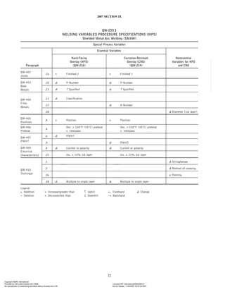


![2007 SECTION IX
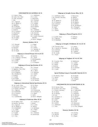
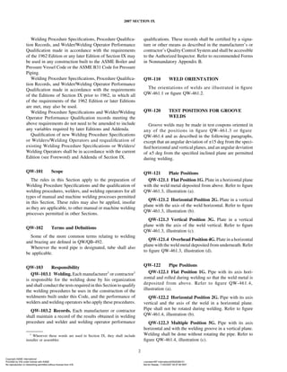
QW-355
SEMIAUTOMATIC GAS METAL-ARC
WELDING (GMAW)
[This Includes Flux-Cored Arc Welding (FCAW)]
Essential Variables
Paragraph Brief of Variables
QW-402 − Backing
.4
Joints
.16 Pipe diameter
QW-403
Base Metals .18 P-Number
.15 F-Number
QW-404
.30 t Weld deposit
Filler Metals
.32 t Limit (S. Cir. Arc.)
.1 + Position
QW-405
Positions .3 ↑↓ Vertical welding
QW-408 − Inert backing
.8
Gas
QW-409 Transfer mode
.2
Electrical
QW-356
MANUAL AND SEMIAUTOMATIC GAS
TUNGSTEN-ARC WELDING (GTAW)
Essential Variables
Paragraph Brief of Variables
QW-402
.4 − Backing
Joints
.16 Pipe diameter
QW-403
Base Metals .18 P-Number
.14 ± Filler
.15 F-Number
QW-404 .22 ± Inserts
Filler Metals
.23 Solid or metal-cored
to flux-cored
.30 t Weld deposit
.1 + Position
QW-405
Positions .3 ↑↓ Vertical welding
QW-408
.8 − Inert backing
Gas
QW-409
.4 Current or polarity
Electrical
57
QW-357
MANUAL AND SEMIAUTOMATIC
PLASMA-ARC WELDING (PAW)
Essential Variables
Paragraph Brief of Variables
QW-402
.4 − Backing
Joints
.16 Pipe diameter
QW-403
Base Metals .18 P-Number
.14 ± Filler
.15 F-Number
QW-404 .22 ± Inserts
Filler Metals
.23 Solid or metal-cored
to flux-cored
.30 t Weld deposit
.1 + Position
QW-405
Positions .3 ↑↓ Vertical welding
QW-408
.8 − Inert backing
Gas
Legend for QW-352 through QW-357:
Change ↑ Uphill
+ Addition ↓ Downhill
− Deletion
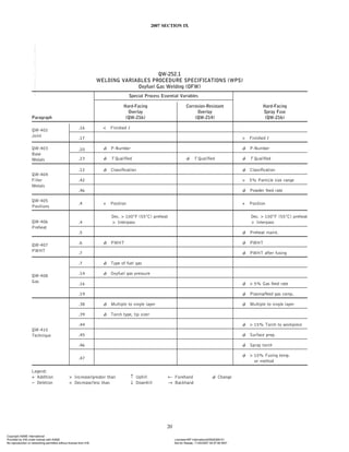
QW-360 WELDING VARIABLES FOR
WELDING OPERATORS
QW-361 General
A welding operator shall be requalified whenever a
change is made in one of the following essential variables
(QW-361.1 and QW-361.2). There may be exceptions or
additional requirements for the processes of QW-362,
QW-363, and the special processes of QW-380.
QW-361.1 Essential Variables — Automatic
Welding
(a) A change from automatic to machine welding.
(b) A change in the welding process.
(c) For electron beam and laser welding, the addition
or deletion of filler metal.
(d) For laser welding, a change in laser type (e.g., a
change from CO2 to YAG).
(e) For friction welding, a change from continous drive
to inertia welding or vice versa.
(f) For electron beam welding, a change from vacuum
to out-of-vacuum equipment, and vice versa.
QW-361.2 Essential Variables — Machine Welding
(a) A change in the welding process.
(b) A change from direct visual control to remote visual
control and vice-versa.
Copyright ASME International
Provided by IHS under license with ASME Licensee=BP International/5928366101
Not for Resale, 11/20/2007 04:57:06 MST
No reproduction or networking permitted without license from IHS
--`,,,,`,`,`,``,,,`,``,````,,```-`-`,,`,,`,`,,`---](https://image.slidesharecdn.com/asmeix9-240528141859-21339aac/85/ASME-IX-9-2007-Full-Version-pdf-82-320.jpg)


![2007 SECTION IX
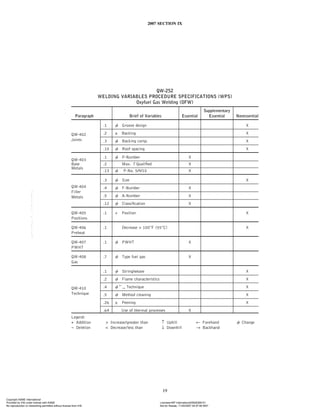
QW-408.13 A change in the position or orientation of
plasma-removing gas jet relative to the workpiece (e.g.,
coaxial transverse to beam).
QW-408.14 A change in the oxygen or fuel gas pres-
sure beyond the range qualified.
QW-408.16 A change of more than 5% in the flow
rate of the plasma-arc gas or powdered metal feed gas
recorded on the PQR.
QW-408.17 A change in the plasma-arc gas, shielding
gas, or powdered metal feed gas from a single gas to any
other single gas, or to a mixture of gases, or vice versa.
QW-408.18 A change of more than 10% in the gas
mixture composition of the plasma-arc gas, shielding gas,
or powdered metal feed gas recorded on the PQR.
QW-408.19 A change in the nominal composition of
the powder feed gas or (plasma-arc spray) plasma gas
qualified.
QW-408.20 A change of more than 5% in the plasma
gas flow rate range qualified.
QW-408.21 A change in the flow rate of the orifice or
shielding gas.
QW-408.22 A change in the shielding gas type, gas
pressure, or purging time.
QW-408.23 For titanium, zirconium, and their alloys,
the deletion of one or more of the following:
(a) shielding gas
(b) trailing shielding gas
(c) backing gas
QW-408.24 For gas-shielded processes, the maximum
moisture content (dew point) of the shielding gas. Moisture
control may be by specification of shielding gas classifica-
tions in SFA-5.32.
QW-409 Electrical Characteristics
QW-409.1 An increase in heat input, or an increase in
volume of weld metal deposited per unit length of weld,
over that qualified. The increase may be determined by
either of the following:
(a) Heat input [J/in. (J/mm)]
p
Voltage ⴛ Amperage ⴛ 60
Travel Speed [in./min (mm/min)]
(b) Volume of weld metal measured by
(1) an increase in bead size (width ⴛ thickness), or
(2) a decrease in length of weld bead per unit length
of electrode
The requirement for measuring the heat input or volume
of deposited weld metal does not apply when the WPS is
qualified with a PWHT above the upper transformation
68
temperature or when an austenitic material is solution
annealed after welding.
QW-409.2 A change from spray arc, globular arc, or
pulsating arc to short circuiting arc, or vice versa.
QW-409.3 The addition or deletion of pulsing current
to dc power source.
QW-409.4 A change from AC to DC, or vice versa; and
in DC welding, a change from electrode negative (straight
polarity) to electrode positive (reverse polarity), or vice
versa.
QW-409.5 A change of ±15% from the amperage or
voltage ranges in the qualified WPS.
QW-409.6 A change in the beam current of more than
±5%, voltage of more than ±2%, welding speed of more
than ±2%, beam focus current of more than ±5%, gun-to-
work distance of more than ±5%, or a change in oscillation
length or width of more than ±20% from those previously
qualified.
QW-409.7 Any change in the beam pulsing frequency
duration from that qualified.
QW-409.8 A change in the range of amperage, or
except for SMAW and GTAW welding, a change in the
range of voltage. A change in the range of electrode wire
feed speed may be used as an alternative to amperage.
QW-409.9 A change in the arc timing of more than
±1
⁄10 sec.
QW-409.10 A change in amperage of more than ±10%.
QW-409.11 A change in the power source from one
model to another.
QW-409.12 A change in type or size of tungsten elec-
trode.
QW-409.13 A change from one Resistance Welding
Manufacturer’s Association (RWMA) electrode class to
another. In addition, a change in the following:
(a) for spot and projection welding, a change in the
nominal shape or more than 10% of the contact area of
the welding electrode
(b) for seam welding, a change of thickness, profile,
orientation, or diameter of electrodes exceeding 10%
QW-409.14 Addition or deletion of upslope or down-
slope current control, or a change of more than 10% in
the slope current time or amplitude.
QW-409.15
(a) A change of more than 5% in any of the following
from that qualified:
(1) preheating current
(2) preheating current amplitude
(3) preheating current time duration
Copyright ASME International
Provided by IHS under license with ASME Licensee=BP International/5928366101
Not for Resale, 11/20/2007 04:57:06 MST
No reproduction or networking permitted without license from IHS
--`,,,,`,`,`,``,,,`,``,````,,```-`-`,,`,,`,`,,`---](https://image.slidesharecdn.com/asmeix9-240528141859-21339aac/85/ASME-IX-9-2007-Full-Version-pdf-93-320.jpg)
![2007 SECTION IX
(4) electrode pressure
(5) welding current
(6) welding current time duration
(b) A change from AC to DC or vice versa.
(c) The addition or deletion of pulsing current to a DC
power source.
(d) When using pulsing DC current, a change of more
than 5% in the pulse amplitude, frequency, or number of
pulses per cycle from that qualified.
(e) A change of more than 5% in the post-heating cur-
rent time duration from that qualified.
QW-409.17 A change in the power supply primary
voltage or frequency, or in the transformer turns ratio, tap
setting, choke position, secondary open circuit voltage or
phase control setting.
QW-409.18 A change in the procedure or frequency
of tip cleaning.
QW-409.19 Any change in the beam pulsing frequency
and pulse duration from that qualified.
QW-409.20 Any change in the following variables:
mode of operation (from pulsed to continuous and vice
versa), energy distribution across the beam (i.e., multimode
or gaussian).
QW-409.21 Any change in the following variables: a
change of more than 5% in the power delivered to the work
surface as measured by calorimeter or other equivalent
methods; a change of more than 2% in the travel speed; a
change of more than 2% of the ratio of the beam diameter
to focal length; a change of more than 2% of the lens to
work distance.
QW-409.22 An increase of more than 10% in the
amperage used in application for the first layer.
QW-409.23 A change of more than 10% in the ranges
of amperage or voltage qualified.
QW-409.24 A change of more than 10% in the filler
wire wattage recorded on the PQR. Wattage is a function
of current voltage, and stickout dimension.
QW-409.25 A change of more than 10% in the plasma-
arc current or voltage recorded on the PQR.
QW-409.26 For the first layer only, an increase in heat
input of more than 10% or an increase in volume of weld
metal deposited per unit length of weld of more than 10%
over that qualified. The increase may be measured by either
of the following:
(a) Heat input [J/in. (J/mm)]
p
Voltage ⴛ Amperage ⴛ 60
Travel Speed [in./min (mm/min)]
69
(b) Volume of Weld Metal p an increase in bead size
or a decrease in length of weld bead per unit length of
electrode.
QW-409.27 A change in the flashing time of more
than 10%.
QW-409.28 A change in the upset current time by
more than 10%.
QW-409.29
(a) A change in the ratios of heat input or in the volume
of weld metal deposited per unit length beyond the follow-
ing (see figure QW-462.12):
(1) An increase or decrease in the ratio of heat input
between the first tempering bead layer and the weld beads
deposited against the base metal of more than 20% for P-
or S-No. 1 and P- or S-No. 3 metals and 10% for all other
P- or S-Number metals.
(2) An increase or decrease in the ratio of heat input
between the second tempering bead layer and the first
tempering bead layer of more than 20% for P-No. 1 and
P-No. 3 metals and 10% for all other P-Number metals.
(3) The ratio of heat input between subsequent layers
shall be maintained until a minimum of 3
⁄16 in. (5 mm) of
weld metal has been deposited over the base metal.
(4) For qualifications where the basis for acceptance
is impact testing and the filler metal is exempt from temper
bead qualification, the heat input may not exceed 50%
above the heat input qualified for the remaining fill passes.
(5) For qualifications where the basis for acceptance
is hardness testing, a decrease of more than 20% in heat
input for the remainder of the fill passes.
(b) Heat input and volume of weld metal per unit length
of weld shall be measured using the following methods:
(1) For machine or automatic GTAW or PAW, an
increase or decrease of 10% in the power ratio measured as:
Power Ratio p
Amperage ⴛ Voltage
[(WFS/TS) ⴛ Af]
where
Af p the cross-section area of the filler metal wire
TS p the welding travel speed
WFS p the filler metal wire feed speed
(2) For processes other than machine or automatic
GTAW or PAW, heat input shall be measured by any of
the following methods:
(a) see formula
(U.S. Customary Units)
Heat Input (J/in.) p
Voltage ⴛ Amperage ⴛ 60
Travel Speed (in./min)
(SI Units)
Heat Input (J/mm) p
Voltage ⴛ Amperage ⴛ 60
Travel Speed (mm/min)
Copyright ASME International
Provided by IHS under license with ASME Licensee=BP International/5928366101
Not for Resale, 11/20/2007 04:57:06 MST
No reproduction or networking permitted without license from IHS
--`,,,,`,`,`,``,,,`,``,````,,```-`-`,,`,,`,`,,`---](https://image.slidesharecdn.com/asmeix9-240528141859-21339aac/85/ASME-IX-9-2007-Full-Version-pdf-94-320.jpg)
![2007 SECTION IX
(b) Volume of Weld Metal p an increase in bead
size or a decrease in length of weld bead per unit length
of electrode.
(3) If manual GTAW or PAW is used for making in-
process repairs in accordance with QW-290.5, a record of
bead size shall be made.
QW-410 TECHNIQUE
QW-410.1 For manual or semiautomatic welding, a
change from the stringer bead technique to the weave bead
technique, or vice versa.
QW-410.2 A change in the nature of the flame, oxidiz-
ing to reducing, or vice versa.
QW-410.3 A change in the orifice, cup, or nozzle size.
QW-410.4 A change in the welding technique, fore-
hand to backhand, or vice versa.
QW-410.5 A change in the method of initial and
interpass cleaning (brushing, grinding, etc.).
QW-410.6 A change in the method of back gouging.
QW-410.7 For the machine or automatic welding pro-
cess, a change in width, frequency, or dwell time of oscilla-
tion technique.
QW-410.8 A change in the contact tube to work dis-
tance.
QW-410.9 A change from multipass per side to single
pass per side. This limitation does not apply when a WPS
is qualified with a PWHT above the upper transformation
temperature or when an austenitic material is solution
annealed after welding.
QW-410.10 A change from single electrode to multiple
electrode, or vice versa, for machine or automatic welding
only. This limitation does not apply when a WPS is quali-
fied with a PWHT above the upper transformation tempera-
ture or when an austenitic material is solution annealed
after welding.
QW-410.11 A change from closed chamber to out-of-
chamber conventional torch welding in P-No. 51 through
P-No. 53 metals, but not vice versa.
QW-410.12 A change from the melt-in technique to
the keyhole technique of welding, or vice versa, or the
inclusion of both techniques though each has been individ-
ually qualified.
QW-410.14 A change in the angle of the axis of the
beam relative to the workpiece.
QW-410.15 A change in the spacing of multiple elec-
trodes for machine or automatic welding.
QW-410.17 A change in the type or model of the
welding equipment.
70
QW-410.18 An increase in the absolute pressure of
the vacuum welding environment beyond that qualified.
QW-410.19 Any change in filament type, size, or
shape.
QW-410.20 The addition of a wash pass.
QW-410.21 A change of welding from one side to
welding from both sides, or vice versa.
QW-410.22 A change in either of the following stud
welding parameters: a change of stud gun model; a change
in the lift more than ±1
⁄32 in. (0.8 mm).
QW-410.25 A change from manual or semiautomatic
to machine or automatic welding and vice versa.
QW-410.26 The addition or deletion of peening.
QW-410.27 A change in the rotational speed producing
a change in the outside surface velocity [ft/min (m/min)]
greater than ±10% of the outside surface velocity qualified.
QW-410.28 A change in the thrust load greater than
±10% of the thrust load qualified.
QW-410.29 A change in the rotational energy greater
than ±10% of the rotational energy qualified.
QW-410.30 Any change in upset dimension (overall
loss in length of parts being joined) greater than ±10% of
the upset qualified.
QW-410.31 A change in the method of preparing the
base metal prior to welding (e.g., changing from mechani-
cal cleaning to chemical cleaning or to abrasive cleaning,
or vice versa).
QW-410.32 A change of more than 10% in the holding
(forging) pressure prior to or after welding. A change of
more than 10% in the electrode holding time (electrode
duration sequence).
QW-410.33 A change from one welding type to
another, or modification of equipment, including Manufac-
turer, control panel, model number, electrical rating or
capacity, type of electrical energy source, or method of
applying pressure.
QW-410.34 Addition or deletion of an electrode cool-
ing medium and where it is used.
QW-410.35 A change in the distance between arms or
a change in the throat depth.
QW-410.37 A change from single to multiple pass or
vice versa.
QW-410.38 A change from multiple-layer to single
layer cladding/hardsurfacing, or vice versa.
QW-410.39 A change in the torch type or tip size.
Copyright ASME International
Provided by IHS under license with ASME Licensee=BP International/5928366101
Not for Resale, 11/20/2007 04:57:06 MST
No reproduction or networking permitted without license from IHS
--`,,,,`,`,`,``,,,`,``,````,,```-`-`,,`,,`,`,,`---](https://image.slidesharecdn.com/asmeix9-240528141859-21339aac/85/ASME-IX-9-2007-Full-Version-pdf-95-320.jpg)


![2007 SECTION IX
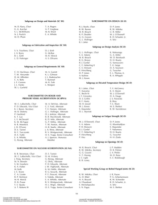
QW-433 Alternate F-Numbers for Welder Performance Qualification
The following tables identify the filler metal or electrode that the welder used during qualification testing as “Qualified
With,” and the electrodes or filler metals that the welder is qualified to use in production welding as “Qualified For.”
See table QW-432 for the F-Number assignments.
F-No. 1 F-No. 1 F-No. 2 F-No. 2 F-No. 3 F-No. 3 F-No. 4 F-No. 4 F-No. 5 F-No. 5
Qualified With →
With Without With Without With Without With Without With Without
Qualified For ↓ Backing Backing Backing Backing Backing Backing Backing Backing Backing Backing
F-No. 1 With
X X X X X X X X X X
Backing
F-No. 1 Without
X
Backing
F-No. 2 With
X X X X X X
Backing
F-No. 2 Without
X
Backing
F-No. 3 With
X X X X
Backing
F-No. 3 Without
X
Backing
F-No. 4 With
X X
Backing
F-No. 4 Without
X
Backing
F-No. 5 With
X X
Backing
F-No. 5 Without
X
Backing
Qualified With Qualified For
Any F-No. 6 All F-No. 6 [Note (1)]
Any F-No. 21 through F-No. 25 All F-No. 21 through F-No. 25
Any F-No. 31, F-No. 32, Only the same F-Number as was
F-No. 33, F-No. 35, F-No. 36, used during the qualification
or F-No. 37 test
F-No. 34 or any F-No. 41 F-No. 34 and all F-No. 41
through F-No. 46 through F-No. 46
Any F-No. 51 through F-No. 55 All F-No. 51 through F-No. 55
Any F-No. 61 All F-No. 61
Any F-No. 71 through F-No. 72 Only the same F-Number as was
used during the qualification
test
NOTE:
(1) Deposited weld metal made using a bare rod not covered by an SFA
Specification but which conforms to an analysis listed in QW-442
shall be considered to be classified as F-No. 6.
137
Copyright ASME International
Provided by IHS under license with ASME Licensee=BP International/5928366101
Not for Resale, 11/20/2007 04:57:06 MST
No reproduction or networking permitted without license from IHS
--`,,,,`,`,`,``,,,`,``,````,,```-`-`,,`,,`,`,,`---](https://image.slidesharecdn.com/asmeix9-240528141859-21339aac/85/ASME-IX-9-2007-Full-Version-pdf-162-320.jpg)
![2007 SECTION IX
QW-440 WELD METAL CHEMICAL COMPOSITION
QW-441 General
Identification of weld metal chemical composition designated on the PQR and WPS shall be as given in QW-404.5.
QW-442
A-NUMBERS
Classification of Ferrous Weld Metal Analysis for Procedure Qualification
Analysis, % [Note (1)]
Types of Weld
A-No. Deposit C Cr Mo Ni Mn Si
1 Mild Steel 0.20 . . . . . . . . . 1.60 1.00
2 Carbon-Molybdenum 0.15 0.50 0.40–0.65 . . . 1.60 1.00
3 Chrome (0.4% to 2%)–Molybdenum 0.15 0.40–2.00 0.40–0.65 . . . 1.60 1.00
4 Chrome (2% to 6%)–Molybdenum 0.15 2.00–6.00 0.40–1.50 . . . 1.60 2.00
5 Chrome (6% to 10.5%)–Molybdenum 0.15 6.00–10.50 0.40–1.50 . . . 1.20 2.00
6 Chrome-Martensitic 0.15 11.00–15.00 0.70 . . . 2.00 1.00
7 Chrome-Ferritic 0.15 11.00–30.00 1.00 . . . 1.00 3.00
8 Chromium–Nickel 0.15 14.50–30.00 4.00 7.50–15.00 2.50 1.00
9 Chromium–Nickel 0.30 19.00–30.00 6.00 15.00–37.00 2.50 1.00
10 Nickel to 4% 0.15 . . . 0.55 0.80–4.00 1.70 1.00
11 Manganese–Molybdenum 0.17 . . . 0.25–0.75 0.85 1.25–2.25 1.00
12 Nickel–Chrome—Molybdenum 0.15 1.50 0.25–0.80 1.25–2.80 0.75–2.25 1.00
NOTE:
(1) Single values shown above are maximum.
138
Copyright ASME International
Provided by IHS under license with ASME Licensee=BP International/5928366101
Not for Resale, 11/20/2007 04:57:06 MST
No reproduction or networking permitted without license from IHS
--`,,,,`,`,`,``,,,`,``,````,,```-`-`,,`,,`,`,,`---](https://image.slidesharecdn.com/asmeix9-240528141859-21339aac/85/ASME-IX-9-2007-Full-Version-pdf-163-320.jpg)
![2007 SECTION IX
QW-450
SPECIMENS
QW-451
Procedure
Qualification
Thickness
Limits
and
Test
Specimens
07
QW-451.1
GROOVE-WELD
TENSION
TESTS
AND
TRANSVERSE-BEND
TESTS
Range
of
Thickness
T
of
Type
and
Number
of
Tests
Required
Base
Metal,
Qualified,
(Tension
and
Guided-Bend
Tests)
[Note
(2)]
Maximum
Thickness
t
of
in.
(mm)
Deposited
Weld
Metal,
Qualified,
Side
Face
Root
[Notes
(1)
and
(2)]
Thickness
T
of
Test
Coupon,
Welded,
in.
(mm)
Tension,
Bend,
Bend,
Bend,
in.
(mm)
Min.
Max.
[Notes
(1)
and
(2)]
QW-150
QW-160
QW-160
QW-160
Less
than
1
⁄
16
(1.5)
T
2
T
2
t
2
.
.
.
2
2
1
⁄
16
to
3
⁄
8
(1.5
to
10),
incl.
1
⁄
16
(1.5)
2
T
2
t
2
Note
(5)
2
2
Over
3
⁄
8
(10),
but
less
than
3
⁄
4
(19)
3
⁄
16
(5)
2
T
2
t
2
Note
(5)
2
2
3
⁄
4
(19)
to
less
than
1
1
⁄
2
(38)
3
⁄
16
(5)
2
T
2
t
when
t
<
3
⁄
4
(19)
2
[Note
(4)]
4
.
.
.
.
.
.
3
⁄
4
(19)
to
less
than
1
1
⁄
2
(38)
3
⁄
16
(5)
2
T
2
T
when
t
≥
3
⁄
4
(19)
2
[Note
(4)]
4
.
.
.
.
.
.
1
1
⁄
2
(38)
to
6
(150),
incl.
3
⁄
16
(5)
8
(200)
[Note
(3)]
2
t
when
t
<
3
⁄
4
(19)
2
[Note
(4)]
4
.
.
.
.
.
.
1
1
⁄
2
(38)
to
6
(150),
incl.
3
⁄
16
(5)
8
(200)
[Note
(3)]
8
(200)
[Note
(3)]
when
t
≥
3
⁄
4
(19)
2
[Note
(4)]
4
.
.
.
.
.
.
Over
6
(150)
3
⁄
16
(5)
1.33
T
[Note
(3)]
2
t
when
t
<
3
⁄
4
(19)
2
[Note
(4)]
4
.
.
.
.
.
.
Over
6
(150)
3
⁄
16
(5)
1.33
T
[Note
(3)]
1.33
T
[Note
(3)]
when
t
≥
3
⁄
4
(19)
2
[Note
(4)]
4
.
.
.
.
.
.
NOTES:
(1)
The
following
variables
further
restrict
the
limits
shown
in
this
table
when
they
are
referenced
in
QW-250
for
the
process
under
consideration:
QW-403.9,
QW-403.10,
QW-404.32,
and
QW-407.4.
Also,
QW-202.2,
QW-202.3,
and
QW-202.4
provide
exemptions
that
supersede
the
limits
of
this
table.
(2)
For
combination
of
welding
procedures,
see
QW-200.4.
(3)
For
the
SMAW,
SAW,
GMAW,
and
GTAW
welding
processes
only;
otherwise
per
Note
(1)
or
2
T
,
or
2
t
,
whichever
is
applicable.
(4)
See
QW-151.1,
QW-151.2,
and
QW-151.3
for
details
on
multiple
specimens
when
coupon
thicknesses
are
over
1
in.
(25
mm).
(5)
Four
side-bend
tests
may
be
substituted
for
the
required
face-
and
root-bend
tests,
when
thickness
T
is
3
⁄
8
in.
(10
mm)
and
over.
139
Copyright ASME International
Provided by IHS under license with ASME Licensee=BP International/5928366101
Not for Resale, 11/20/2007 04:57:06 MST
No reproduction or networking permitted without license from IHS
--`,,,,`,`,`,``,,,`,``,````,,```-`-`,,`,,`,`,,`---](https://image.slidesharecdn.com/asmeix9-240528141859-21339aac/85/ASME-IX-9-2007-Full-Version-pdf-164-320.jpg)
![2007 SECTION IX
QW-451.2
GROOVE-WELD
TENSION
TESTS
AND
LONGITUDINAL-BEND
TESTS
Thickness
t
of
Range
of
Thickness
T
Deposited
Weld
Metal
of
Base
Metal
Qualified,
Type
and
Number
of
Tests
Required
Qualified,
in.
(mm)
in.
(mm)
(Tension
and
Guided-Bend
Tests)
[Notes
(1)
and
(2)]
[Notes
(1)
and
(2)]
[Note
(2)]
Face
Root
Thickness
T
of
Test
Tension,
Bend,
Bend,
Coupon
Welded,
in.
(mm)
Min.
Max.
Max.
QW-150
QW-160
QW-160
Less
than
1
⁄
16
(1.5)
T
2
T
2
t
2
2
2
1
⁄
16
to
3
⁄
8
(1.5
to
10),
incl.
1
⁄
16
(1.5)
2
T
2
t
2
2
2
Over
3
⁄
8
(10)
3
⁄
16
(5)
2
T
2
t
2
2
2
NOTES:
(1)
The
following
variables
further
restrict
the
limits
shown
in
this
table
when
they
are
referenced
in
QW-250
for
the
process
under
consideration:
QW-403.9,
QW-403.10,
QW-404.32,
and
QW-407.4.
Also,
QW-202.2,
QW-202.3,
and
QW-202.4
provide
exemptions
that
supersede
the
limits
of
this
table.
(2)
For
combination
of
welding
procedures,
see
QW-200.4.
140
Copyright ASME International
Provided by IHS under license with ASME Licensee=BP International/5928366101
Not for Resale, 11/20/2007 04:57:06 MST
No reproduction or networking permitted without license from IHS
--`,,,,`,`,`,``,,,`,``,````,,```-`-`,,`,,`,`,,`---](https://image.slidesharecdn.com/asmeix9-240528141859-21339aac/85/ASME-IX-9-2007-Full-Version-pdf-165-320.jpg)
![2007 SECTION IX
QW-451.3
FILLET-WELD TESTS
Type and Number of Tests
Type of Thickness of Test Required [QW-462.4(a) or QW-462.4(d)]
Joint Coupons as Welded, in. Range Qualified Macro
Fillet Per QW-462.4(a) All fillet sizes on all base 5
metal thicknesses and all
diameters
Fillet Per QW-462.4(d) 4
GENERAL NOTE: A production assembly mockup may be substituted in accordance with QW-181.1.1. When a production assembly mockup is
used, the range qualified shall be limited to the fillet weld size, base metal thickness, and configuration of the mockup. Alternatively, multiple
production assembly mockups may be qualified. The range of thickness of the base metal qualified shall be no less than the thickness of the thinner
member tested and no greater than the thickness of the thicker member tested. The range for fillet weld sizes qualified shall be limited to no less
than the smallest fillet weld tested and no greater than the largest fillet weld tested. The configuration of production assemblies shall be the same
as that used in the production assembly mockup.
QW-451.4
FILLET WELDS QUALIFIED BY GROOVE-WELD TESTS
Thickness T of Test
Coupon (Plate or Pipe) Type and Number of Tests
as Welded Range Qualified Required
All groove tests All fillet sizes on all base Fillet welds are qualified when
metal thicknesses and all the groove weld is qualified
diameters in accordance with either
QW-451.1 or QW-451.2
(see QW-202.2)
141
Copyright ASME International
Provided by IHS under license with ASME Licensee=BP International/5928366101
Not for Resale, 11/20/2007 04:57:06 MST
No reproduction or networking permitted without license from IHS
--`,,,,`,`,`,``,,,`,``,````,,```-`-`,,`,,`,`,,`---](https://image.slidesharecdn.com/asmeix9-240528141859-21339aac/85/ASME-IX-9-2007-Full-Version-pdf-166-320.jpg)
![2007 SECTION IX
QW-452 Performance Qualification Thickness
Limits and Test Specimens
QW-452.1 Groove-Weld Test. The following tables identify the required type and number of tests and the thickness
of weld metal qualified.
QW-452.1(a)
TEST SPECIMENS
Type and Number of Examinations and Test Specimens Required
Face Bend Root Bend
Visual Side Bend QW-462.3(a) or QW-462.3(a) or
Thickness of Weld Examination QW-462.2 QW-462.3(b) QW-462.3(b)
Metal, in. (mm) per QW-302.4 [Note (1)] [Notes (1), (2)] [Notes (1), (2)]
Less than 3
⁄8 (10) X . . . 1 1
3
⁄8 (10) to less than X 2 [Note (3)] Note (3) Note (3)
3
⁄4 (19)
3
⁄4 (19) and over X 2 . . . . . .
GENERAL NOTE: The “Thickness of Weld Metal” is the total weld metal thickness deposited by all welders
and all processes in the test coupon exclusive of the weld reinforcement.
NOTES:
(1) To qualify using positions 5G or 6G, a total of four bend specimens are required. To qualify using a
combination of 2G and 5G in a single test coupon, a total of six bend specimens are required. See
QW-302.3. The type of bend test shall be based on weld metal thickness.
(2) Coupons tested by face and root bends shall be limited to weld deposit made by one welder with one or
two processes or two welders with one process each. Weld deposit by each welder and each process shall
be present on the convex surface of the appropriate bent specimen.
(3) One face and root bend may be substituted for the two side bends.
QW-452.1(b)
THICKNESS OF WELD METAL QUALIFIED
Thickness, t, of Weld Metal in Thickness of Weld
the Coupon, in. (mm) Metal Qualified
[Notes (1) and (2)] [Note (3)]
All 2t
1
⁄2 (13) and over with a Maximum to be
minimum of three layers welded
NOTES:
(1) When more than one welder and/or more than one process and
more than one filler metal F-Number is used to deposit weld metal
in a coupon, the thickness, t, of the weld metal in the coupon
deposited by each welder with each process and each filler metal
F-Number in accordance with the applicable variables under QW-
404 shall be determined and used individually in the “Thickness,
t, of Weld Metal in the Coupon” column to determine the “Thick-
ness of Weld Metal Qualified.”
(2) Two or more pipe test coupons with different weld metal thickness
may be used to determine the weld metal thickness qualified and
that thickness may be applied to production welds to the smallest
diameter for which the welder is qualified in accordance with
QW-452.3.
(3) Thickness of test coupon of 3
⁄4 in. (19 mm) or over shall be used
for qualifying a combination of three or more welders each of
whom may use the same or a different welding process.
142
Copyright ASME International
Provided by IHS under license with ASME Licensee=BP International/5928366101
Not for Resale, 11/20/2007 04:57:06 MST
No reproduction or networking permitted without license from IHS
--`,,,,`,`,`,``,,,`,``,````,,```-`-`,,`,,`,`,,`---](https://image.slidesharecdn.com/asmeix9-240528141859-21339aac/85/ASME-IX-9-2007-Full-Version-pdf-167-320.jpg)

![2007 SECTION IX
QW-452.5
FILLET-WELD TEST
Type and Number of Tests Required
Thickness of Test
[QW-462.4(b) or QW-462.4(c)]
Coupon as Welded,
Type of Joint in. (mm) Qualified Range Macro Fracture
Tee fillet 3
⁄16–3
⁄8 (5–10) All base material thicknesses, fillet sizes, and diameters 1 1
27
⁄8(73) O.D. and over [Note (1)]
Less than 3
⁄16 (5) T to 2T base material thickness, T maximum fillet size, 1 1
and all diameters 27
⁄8 (73) O.D. and over [Note (1)]
GENERAL NOTE: Production assembly mockups may be substituted in accordance with QW-181.2.1. When production assembly mockups are
used, range qualified shall be limited to the fillet sizes, base metal thicknesses, and configuration of the mockup.
NOTE:
(1) 27
⁄8 in. (73 mm) O.D. is considered the equivalent of NPS 21
⁄2 (DN 65). For smaller diameter qualifications, refer to QW-452.4 or QW-452.6.
QW-452.6
FILLET QUALIFICATION BY GROOVE-WELD TESTS
Thickness of Test Coupon as Welded, Type and Number of
Type of Joint in. (mm) Qualified Range Tests Required
Any groove All thicknesses All base material thicknesses, Fillet welds are qualified when a welder/welding
fillet sizes, and diameters operator qualifies on a groove weld test
144
Copyright ASME International
Provided by IHS under license with ASME Licensee=BP International/5928366101
Not for Resale, 11/20/2007 04:57:06 MST
No reproduction or networking permitted without license from IHS
--`,,,,`,`,`,``,,,`,``,````,,```-`-`,,`,,`,`,,`---](https://image.slidesharecdn.com/asmeix9-240528141859-21339aac/85/ASME-IX-9-2007-Full-Version-pdf-169-320.jpg)
![2007 SECTION IX
QW-453
PROCEDURE/PERFORMANCE QUALIFICATION THICKNESS LIMITS AND TEST
SPECIMENS FOR HARD-FACING (WEAR-RESISTANT) AND CORROSION-
RESISTANT OVERLAYS
Corrosion-Resistant Overlay Hard-facing Overlay (Wear-Resistant)
[Note (1)] [Note (2)]
Thickness of Test Nominal Base Metal Type and Number of Nominal Base Metal Type and Number
Coupon (T ) Thickness Qualified (T ) Tests Required Thickness Qualified (T ) of Tests Required
Procedure Qualification
Testing
Less than 1 in. (25 mm) T
Notes (4), (5), and (9) Notes (3), (7), (8), and (9)
T qualified to unlimited
1 in. (25 mm)
to unlimited
冧
1 in. (25 mm) and over T
T qualified up to 1 in.
(25 mm)
1 in. (25 mm) to
unlimited
冧
Performance
Qualification
Testing
Less than 1 in. (25 mm) T
Note (6) Notes (8) and (10)
T qualified to unlimited
1 in. (25 mm)
to unlimited
冧
T qualified to unlimited
1 in. (25 mm)
to unlimited
冧
1 in. (25 mm) and over T
NOTES:
(1) The qualification test coupon shall consist of base metal not less than 6 in. (150 mm) ⴛ 6 in. (150 mm). The weld overlay cladding shall be
a minimum of 11
⁄2 in. (38 mm) wide by approximately 6 in. (150 mm) long. For qualification on pipe, the pipe length shall be a minimum
of 6 in. (150 mm), and a minimum diameter to allow the required number of test specimens. The weld overlay shall be continuous around
the circumference of the test coupon. For processes (performance qualification only) depositing a weld bead width greater than 1
⁄2 in. (13 mm)
wide, the weld overlay shall consist of a minimum of three weld beads in the first layer.
(2) The test base metal coupon shall have minimum dimensions of 6 in. (150 mm) wide ⴛ approximately 6 in. (150 mm) long with a hard-faced
layer a minimum of 11
⁄2 in. (38 mm) wide ⴛ 6 in. (150 mm) long. The minimum hard-faced thickness shall be as specified in the Welding
Procedure Specification. Alternatively, the qualification may be performed on a test base metal coupon that represents the size of the production
part. For qualification on pipe, the pipe length shall be 6 in. (150 mm) minimum, and of a minimum diameter to allow the required number
of test specimens. The weld overlay shall be continuous around the circumference of the test coupon.
(3) The hard-facing surface shall be examined by the liquid penetrant method and shall meet the acceptance standards in QW-195.2 or as specified
in the WPS. Surface conditioning prior to liquid penetrant examination is permitted.
(4) The corrosion-resistant surface shall be examined by the liquid penetrant method and shall meet the acceptance standards as specified in QW-195.
(5) Following the liquid penetrant examination, four guided side-bend tests shall be made from the test coupon in accordance with QW-161. The
test specimens shall be cut so that there are either two specimens parallel and two specimens perpendicular to the direction of the welding,
or four specimens perpendicular to the direction of the welding. For coupons that are less than 3
⁄8 in. (10 mm) thick, the width of the side-
bend specimens may be reduced to the thickness of the test coupon. The side-bend specimens shall be removed from locations specified in QW-
462.5(c) or QW-462.5(d).
(6) The test coupon shall be sectioned to make side-bend test specimens perpendicular to the direction of the welding in accordance with QW-161.
Test specimens shall be removed at locations specified in QW-462.5(c) or QW-462.5(d).
(7) After surface conditioning to the minimum thickness specified in the WPS, a minimum of three hardness readings shall be made on each of
the specimens from the locations shown in QW-462.5(b) or QW-462.5(e). All readings shall meet the requirements of the WPS.
(8) The base metal shall be sectioned transversely to the direction of the hard-facing overlay. The two faces of the hard-facing exposed by sectioning
shall be polished and etched with a suitable etchant and shall be visually examined with ⴛ5 magnification for cracks in the base metal or the
heat-affected zone, lack of fusion, or other linear defects. The overlay and the base metal shall meet the requirements specified in the WPS.
All exposed faces shall be examined. See QW-462.5(b) for pipe and QW-462.5(e) for plate.
(9) When a chemical composition is specified in the WPS, chemical analysis specimens shall be removed at locations specified in QW-462.5(b)
or QW-462.5(e). The chemical analysis shall be performed in accordance with QW-462.5(a) and shall be within the range specified in the
WPS. This chemical analysis is not required when a chemical composition is not specified on the WPS.
(10) At a thickness greater than or equal to the minimum thickness specified in the WPS, the weld surface shall be examined by the liquid
penetrant method and shall meet the acceptance standards in QW-195.2 or as specified in the WPS. Surface conditioning prior to liquid
penetrant examination is permitted.
145
Copyright ASME International
Provided by IHS under license with ASME Licensee=BP International/5928366101
Not for Resale, 11/20/2007 04:57:06 MST
No reproduction or networking permitted without license from IHS
--`,,,,`,`,`,``,,,`,``,````,,```-`-`,,`,,`,`,,`---](https://image.slidesharecdn.com/asmeix9-240528141859-21339aac/85/ASME-IX-9-2007-Full-Version-pdf-170-320.jpg)


![2007 SECTION IX
QW-461.9
PERFORMANCE QUALIFICATION — POSITION AND DIAMETER LIMITATIONS
(Within the Other Limitations of QW-303)
Position and Type Weld Qualified [Note (1)]
Groove
Plate and Pipe
Qualification Test Fillet
Over 24 in. Pipe ≤ 24 in.
Weld Position (610 mm) O.D. (610 mm) O.D. Plate and Pipe
Plate — Groove 1G F F [Note (2)] F
2G F,H F,H [Note (2)] F,H
3G F,V F [Note (2)] F,H,V
4G F,O F [Note (2)] F,H,O
3G and 4G F,V,O F [Note (2)] All
2G, 3G, and 4G All F,H [Note (2)] All
Special Positions (SP) SP,F SP,F SP,F
Plate — Fillet 1F . . . . . . F [Note (2)]
2F . . . . . . F,H [Note (2)]
3F . . . . . . F,H,V [Note (2)]
4F . . . . . . F,H,O [Note (2)]
3F and 4F . . . . . . All [Note (2)]
Special Positions (SP) . . . . . . SP,F [Note (2)]
Pipe — Groove [Note (3)] 1G F F F
2G F,H F,H F,H
5G F,V,O F,V,O All
6G All All All
2G and 5G All All All
Special Positions (SP) SP,F SP,F SP,F
Pipe — Fillet [Note (3)] 1F . . . . . . F
2F . . . . . . F,H
2FR . . . . . . F,H
4F . . . . . . F,H,O
5F . . . . . . All
Special Positions (SP) . . . . . . SP,F
NOTES:
(1) Positions of welding as shown in QW-461.1 and QW-461.2.
F p Flat
H p Horizontal
V p Vertical
O p Overhead
(2) Pipe 27
⁄8 in. (73 mm) O.D. and over.
(3) See diameter restrictions in QW-452.3, QW-452.4, and QW-452.6.
151
Copyright ASME International
Provided by IHS under license with ASME Licensee=BP International/5928366101
Not for Resale, 11/20/2007 04:57:06 MST
No reproduction or networking permitted without license from IHS
--`,,,,`,`,`,``,,,`,``,````,,```-`-`,,`,,`,`,,`---](https://image.slidesharecdn.com/asmeix9-240528141859-21339aac/85/ASME-IX-9-2007-Full-Version-pdf-176-320.jpg)

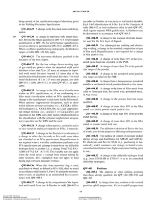
![2007 SECTION IX
QW-462.1(b) TENSION — REDUCED SECTION — PIPE
This section machined
preferably by milling
Grind or machine the minimum
amount needed to obtain plane
parallel faces over the reduced
section W. No more material
than is needed to perform the
test shall be removed.
y
W
x
1/4 in. (6 mm)
1/4 in.
(6 mm)
1/4 in.
(6 mm)
1/4 in.
(6 mm)
1
i
n
.
(
2
5
m
m
)
R
m
i
n
.
Edge of widest
face of weld
On ferrous material
these edges may
be thermally cut
10 in. (250 mm) or
as required
QW-462.1(c) TENSION — REDUCED SECTION ALTERNATE FOR PIPE
T [Note (1)]
y
x
3 in. (75 mm) min.
11/16 in. (27 mm)
1/2 in. (13 mm)
Rad. 1 in. (25 mm) min.
Edge of widest face of weld
NOTES:
(1) The weld reinforcement shall be ground or machined so that
the weld thickness does not exceed the base metal thickness
T. Machine minimum amount to obtain approximately parallel
surfaces.
(2) The reduced section shall not be less than the width of the
weld plus 2y.
Reduced section
[Note (2)]
153
Copyright ASME International
Provided by IHS under license with ASME Licensee=BP International/5928366101
Not for Resale, 11/20/2007 04:57:06 MST
No reproduction or networking permitted without license from IHS
--`,,,,`,`,`,``,,,`,``,````,,```-`-`,,`,,`,`,,`---](https://image.slidesharecdn.com/asmeix9-240528141859-21339aac/85/ASME-IX-9-2007-Full-Version-pdf-178-320.jpg)


![2007 SECTION IX
QW-462.2 SIDE BEND
x T
y
w
1/8 in. (3 mm) min.
R1 = 1/8 in.
(3 mm) max.
6 in. (150 mm) or as required
(1a) For procedure qualification of materials other than P-No. 1 in QW-422,
if the surfaces of the side bend test specimens are gas cut, removal by
machining or grinding of not less than 1/8 in. (3 mm) from the surface
shall be required.
(1b) Such removal is not required for P-No. 1 materials, but any resulting
roughness shall be dressed by machining or grinding.
(2) For performance qualification of all materials in QW-422, if the surfaces of
side bend tests are gas cut, any resulting roughness shall be dressed by
machining or grinding.
1/8 (3) 3/8 (10)
1/8 (3) 3/8 (10)
w, in. (mm)
y, in. (mm)
Notes (1)
and (2)
T, in. (mm)
T
[Note (1)]
P-No. 23,
F-No. 23, or
P-No. 35
All other
metals
GENERAL NOTE: Weld reinforcement and backing strip or backing ring, if any, may be removed flush with the surface of the specimen. Thermal
cutting, machining, or grinding may be employed. Cold straightening is permitted prior to removal of the reinforcement.
NOTES:
(1) When weld deposit t is less than coupon thickness T, side-bend specimen thickness may be t.
(2) When coupon thickness T equals or exceeds 11
⁄2 in. (38 mm), use one of the following:
(a) Cut specimen into multiple test specimens of thickness y of approximately equal dimensions [3
⁄4 in. (19 mm) to 11
⁄2 in. (38 mm)].
y p tested specimen thickness when multiple specimens are taken from one coupon.
(b) The specimen may be bent at full width. See requirements on jig width in QW-466.1.
156
Copyright ASME International
Provided by IHS under license with ASME Licensee=BP International/5928366101
Not for Resale, 11/20/2007 04:57:06 MST
No reproduction or networking permitted without license from IHS
--`,,,,`,`,`,``,,,`,``,````,,```-`-`,,`,,`,`,,`---](https://image.slidesharecdn.com/asmeix9-240528141859-21339aac/85/ASME-IX-9-2007-Full-Version-pdf-181-320.jpg)


![2007 SECTION IX
QW-462.5(d) PLATE BEND SPECIMENS — CORROSION-RESISTANT WELD METAL OVERLAY
NOTES:
(1) Location for required test specimen removal — Procedure (QW-453). Four-side-bend test specimens are required
for each position.
(2) Location for required test specimen removal — Performance (QW-453). Two-side-bend test specimens are
required for each position.
Discard
Discard
Discard
Discard
Longitudinal
side bends
[Note (1)]
Transverse
side bends
[Notes (1), (2)]
As
required
6
in.
(150
mm)
min.
6
in.
(150
mm)
min.
6 in. (150 mm) min.
6 in. (150 mm) min.
Transverse
side bends
[Note (1)]
163
Copyright ASME International
Provided by IHS under license with ASME Licensee=BP International/5928366101
Not for Resale, 11/20/2007 04:57:06 MST
No reproduction or networking permitted without license from IHS
--`,,,,`,`,`,``,,,`,``,````,,```-`-`,,`,,`,`,,`---](https://image.slidesharecdn.com/asmeix9-240528141859-21339aac/85/ASME-IX-9-2007-Full-Version-pdf-188-320.jpg)


![2007 SECTION IX
QW-462.9 SPOT WELDS IN SHEET
5 in. (125 mm) min.
(a) Single Spot
Shear Specimen
(b) Multiple Spot
Shear Specimen
[Note (2)]
W W
W
W
L [Note (1)]
L
Nominal Thickness of Thinner W, in.
Sheet, in. (mm) (mm) Min.
Over 0.008 to 0.030 (0.20 to 0.8) 0.68 (17)
Over 0.030 to 0.100 (0.8 to 2.5) 1.00 (25)
Over 0.100 to 0.130 (2.5 to 3) 1.25 (30)
Over 0.130 (3) 1.50 (38)
NOTES:
(1) L shall be not less than 4W.
(2) Sketch (b) shall be made of 5 specimens or more.
168
Copyright ASME International
Provided by IHS under license with ASME Licensee=BP International/5928366101
Not for Resale, 11/20/2007 04:57:06 MST
No reproduction or networking permitted without license from IHS
--`,,,,`,`,`,``,,,`,``,````,,```-`-`,,`,,`,`,,`---](https://image.slidesharecdn.com/asmeix9-240528141859-21339aac/85/ASME-IX-9-2007-Full-Version-pdf-193-320.jpg)


![2007 SECTION IX
QW-462.12
NOMENCLATURE
FOR
TEMPER
BEAD
WELDING
S
[Note
(1)])
S
[Note
(1)]
S
[Note
(1)]
S
[Note
(1)]
LEGEND
See
Note
(2)
Weld
Beads
against
Base
Metal
First
Layer
Tempering
Beads
Second
Layer
Tempering
Beads
Fill
Weld
Beads
Surface
Temper
Weld
Reinforcing
Beads
Partially
Completed
Partial-Penetration
Weld
Completed
Partial-Penetration
Weld
Approx.
0.040
in.
(1
mm)
Also
showing
location
of
hardness
traverses
when
hardness
testing
is
used.
Also
showing
permissible
locations
and
orientations
of
hardness
traverses.
Also
showing
location
of
hardness
traverses
when
hardness
testing
is
used.
Typical
Groove
Weld
Typical
Fillet
Weld
Overlay
Weld
Approx.
0.040
in.
(1
mm)
Approx.
0.040
in.
(1
mm)
Approx.
0.040
in.
(1
mm)
Approx.
0.040
in.
(1
mm)
GENERAL
NOTES:
(a)
Weld
beads
shown
above
may
be
deposited
in
any
sequence
that
will
result
in
placement
of
the
beads
as
shown.
(b)
Surface
temper
reinforcing
beads
may
cover
the
entire
weld
surface,
or
may
only
be
placed
at
the
toe
of
the
weld;
they
may
or
may
not
be
mechanically
removed.
NOTES:
(1)
The
distance,
S
,
is
measured
from
the
toe
of
the
weld
to
the
edge
of
the
temper
beads.
Measurements
shall
be
made
parallel
to
the
base
metal
surface.
(2)
Beads
near
the
finished
surface
may
be
both
tempering
beads
and
surface
temper
reinforcing
beads.
171
Copyright ASME International
Provided by IHS under license with ASME Licensee=BP International/5928366101
Not for Resale, 11/20/2007 04:57:06 MST
No reproduction or networking permitted without license from IHS
--`,,,,`,`,`,``,,,`,``,````,,```-`-`,,`,,`,`,,`---](https://image.slidesharecdn.com/asmeix9-240528141859-21339aac/85/ASME-IX-9-2007-Full-Version-pdf-196-320.jpg)


![2007 SECTION IX
QW-466.1 TEST JIG DIMENSIONS (CONT’D)
SI Units
Thickness of
Material Specimen, mm A, mm B, mm C, mm D, mm
P-No. 23 to P-No. 21 through P-No. 25; P-No. 3 52.4 26.2 60.4 30.2
21 through P-No. 25 with F-No. 23; P-No. 35; t p 3 or less 161
⁄2t 81
⁄4t 181
⁄2t + 1.6 91
⁄4t + 0.8
any P-No. metal with F-No. 33, 36, or 37
P-No. 11; P-No.25 to P-No. 21 or P-No. 22 or 10 63.5 31.8 85.8 42.9
P-No. 25 t p 10 or less 62
⁄3t 31
⁄3t 82
⁄3t + 3.2 41
⁄3t + 1.6
P-No. 51; P-No. 49 10 76.2 38.1 98.4 49.2
t p 10 or less 8t 4t 10t + 3.2 5t + 1.6
P-No. 52; P-No. 53; P-No. 61; P-No. 62 10 95.2 47.6 117.5 58.7
t p 10 or less 10t 5t 12t + 3.2 6t + 1.6
All others with greater than or equal to 20% elon- 10 38.1 19.0 60.4 30.2
gation t p 10 or less 4t 2t 6t + 3.2 3t + 1.6
All others with less than 20% elongation t p (see Note b) 327
⁄8t, 167
⁄16t, 347
⁄8t + 1.6 177
⁄16t + 0.8
max. max. max. max.
GENERAL NOTES:
(a) For P-Numbers, see QW/QB-422; for F-Numbers, see QW-432.
(b) The dimensions of the test jig shall be such as to give the bend test specimen a calculated percent outer fiber elongation equal to at least that
of the base material with the lower minimum elongation as specified in the base material specification.
percent outer fiber elongation p
100t
A + t
The following formula is provided for convenience in calculating the bend specimen thickness:
thickness of specimen (t) p
A ⴛ percent elongation
[100 − (percent elongation)]
(c) For guided-bend jig configuration, see QW-466.2, QW-466.3, and QW-466.4.
(d) The weld and heat-affected zone, in the case of a transverse weld bend specimen, shall be completely within the bend portion of the specimen
after testing.
183
Copyright ASME International
Provided by IHS under license with ASME Licensee=BP International/5928366101
Not for Resale, 11/20/2007 04:57:06 MST
No reproduction or networking permitted without license from IHS
--`,,,,`,`,`,``,,,`,``,````,,```-`-`,,`,,`,`,,`---](https://image.slidesharecdn.com/asmeix9-240528141859-21339aac/85/ASME-IX-9-2007-Full-Version-pdf-208-320.jpg)


![2007 SECTION IX
QW-470 ETCHING — PROCESSES AND
REAGENTS
QW-471 General
The surfaces to be etched should be smoothed by filing,
machining, or grinding on metallographic papers. With
different alloys and tempers, the etching period will vary
from a few seconds to several minutes, and should be
continued until the desired contrast is obtained. As a protec-
tion from the fumes liberated during the etching process,
this work should be done under a hood. After etching, the
specimens should be thoroughly rinsed and then dried with
a blast of warm air. Coating the surface with a thin clear
lacquer will preserve the appearance.
QW-472 For Ferrous Metals
Etching solutions suitable for carbon and low alloy
steels, together with directions for their use, are suggested
in QW-472.1 through QW-472.4.
QW-472.1 Hydrochloric Acid. Hydrochloric (muri-
atic) acid and water, equal parts, by volume. The solution
should be kept at or near the boiling temperature during
the etching process. The specimens are to be immersed in
the solution for a sufficient period of time to reveal all
lack of soundness that might exist at their cross-sectional
surfaces.
QW-472.2 Ammonium Persulfate. One part of ammo-
nium persulfate to nine parts of water, by weight. The
solution should be used at room temperature, and should
be applied by vigorously rubbing the surface to be etched
with a piece of cotton saturated with the solution. The
etching process should be continued until there is a clear
definition of the structure in the weld.
QW-472.3 Iodine and Potassium Iodide. One part of
powdered iodine (solid form), two parts of powdered potas-
sium iodide, and ten parts of water, all by weight. The
solution should be used at room temperature, and brushed
on the surface to be etched until there is a clear definition
or outline of the weld.
QW-472.4 Nitric Acid. One part of nitric acid and three
parts of water, by volume.
CAUTION: Always pour the acid into the water. Nitric acid causes
bad stains and severe burns.
The solution may be used at room temperature and
applied to the surface to be etched with a glass stirring
rod. The specimens may also be placed in a boiling solution
of the acid, but the work should be done in a well-ventilated
room. The etching process should be continued for a suffi-
cient period of time to reveal all lack of soundness that
might exist at the cross-sectional surfaces of the weld.
187
QW-473 For Nonferrous Metals
The following etching reagents and directions for their
use are suggested for revealing the macrostructure.
QW-473.1 Aluminum and Aluminum-Base Alloys
Solution Volume
Hydrochloric acid (concentrated) 15 ml
Hydrofluoric acid (48%) 10 ml
Water 85 ml
This solution is to be used at room temperature, and
etching is accomplished by either swabbing or immersing
the specimen.
QW-473.2 For Copper and Copper-Base Alloys:
Cold Concentrated Nitric Acid. Etching is accomplished
by either flooding or immersing the specimen for several
seconds under a hood. After rinsing with a flood of water,
the process is repeated with a 50-50 solution of concen-
trated nitric acid and water.
In the case of the silicon bronze alloys, it may be neces-
sary to swab the surface to remove a white (SiO2) deposit.
QW-473.3 For Nickel and Nickel-Base Alloys
Material Formula
Nickel Nitric Acid or Lepito’s Etch
Low Carbon Nickel Nitric Acid or Lepito’s Etch
Nickel–Copper (400) Nitric Acid or Lepito’s Etch
Nickel–Chromium–Iron Aqua Regia or Lepito’s Etch
(600 and 800)
MAKEUP OF FORMULAS FOR AQUA REGIA AND
LEPITO’S ETCH
Aqua Regia Lepito’s Etch
Solution [(1), (2)] [(2), (3)]
Nitric Acid, Concentrated — HNO3 1 part 3 ml
Hydrochloric Acid, Concentrated —
HCL 2 parts 10 ml
Ammonium Sulfate — (NH4)2(SO4) . . . 1.5 g
Ferric Chloride — FeCl3 . . . 2.5 g
Water . . . 7.5 ml
NOTES:
(1) Warm the parts for faster action.
(2) Etching is accomplished by either swabbing or immersing the
specimen.
(3) Mix solution as follows:
(a) Dissolve (NH4)2(SO4) in H2O.
(b) Dissolve powdered FeCl3 in warm HCl.
(c) Mix (a) and (b) above and add HNO3.
QW-473.4 For Titanium
Solution Kroll’s Etch Keller’s Etch
Hydrofluoric acid (48%) 1 to 3 ml 1
⁄2 ml
Nitric acid (concentrated) 2 to 6 ml 21
⁄2 ml
Hydrochloric Acid . . . 11
⁄2 ml
(concentrated)
Water To make 100 ml To make 100 ml
Copyright ASME International
Provided by IHS under license with ASME Licensee=BP International/5928366101
Not for Resale, 11/20/2007 04:57:06 MST
No reproduction or networking permitted without license from IHS
--`,,,,`,`,`,``,,,`,``,````,,```-`-`,,`,,`,`,,`---](https://image.slidesharecdn.com/asmeix9-240528141859-21339aac/85/ASME-IX-9-2007-Full-Version-pdf-212-320.jpg)


![2007 SECTION IX
ARTICLE XII
BRAZING PROCEDURE QUALIFICATIONS
QB-200 GENERAL
QB-200.1 Each manufacturer or contractor shall pre-
pare written Brazing Procedure Specifications, which are
defined as follows.
(a) Brazing Procedure Specification (BPS). A BPS is a
written qualified brazing procedure prepared to provide
direction for making production brazes to Code require-
ments. The BPS or other documents [see QB-200.1(e)]
may be used to provide direction to the brazer or brazing
operator to assure compliance with the Code requirements.
(b) Contents of the BPS. The completed BPS shall
describe all of the essential and nonessential variables for
each brazing process used in the BPS. These variables are
listed in QB-250 and are defined in Article XIV, Braz-
ing Data.
The BPS shall reference the supporting Procedure Quali-
fication Record(s) (PQR) described in QB-200.2. The man-
ufacturer or contractor may include any other information
in the BPS that may be helpful in making a Code braze.
(c) Changes to the BPS. Changes may be made in the
nonessential variables of a BPS to suit production require-
ments without requalification provided such changes are
documented with respect to the essential and nonessential
variables for each process. This may be by amendment to
the BPS or by use of a new BPS.
Changes in essential variables require requalification of
the BPS [new or additional PQRs to support the change
in essential variable(s)].
(d) Format of the BPS. The information required to be
in the BPS may be in any format, written or tabular, to fit
the needs of each manufacturer or contractor, as long as
every essential and nonessential variable outlined in
QB-250 is included or referenced.
Form QB-482 (see Nonmandatory Appendix B) has been
provided as a guide for the BPS. It is only a guide and
does not list all required data for all brazing processes.
(e) Availability of the BPS. A BPS used for Code pro-
duction brazing shall be available for reference and review
by the Authorized Inspector (AI) at the fabrication site.
QB-200.2 Each manufacturer or contractor shall be
required to prepare a procedure qualification record, which
is defined as follows.
203
(a) Procedure Qualification Record (PQR). A PQR is
a record of the brazing data used to braze a test coupon.
The PQR is a record of variables recorded during the
brazing of the test coupons. It also contains the test results
of the tested specimens. Recorded variables normally fall
within a small range of the actual variables that will be
used in production brazing.
(b) Contents of the PQR. The completed PQR shall
document all essential variables of QB-250 for each braz-
ing process used during the brazing of the test coupon.
Nonessential or other variables used during the brazing of
the test coupon may be recorded at the manufacturer’s or
contractor’s option. All variables, if recorded, shall be the
actual variables (including ranges) used during the brazing
of the test coupon. If variables are not monitored during
brazing, they shall not be recorded. It is not intended that
the full range or the extreme of a given range of variables
to be used in production be used during qualification unless
required due to a specific essential variable.
The PQR shall be certified accurate by the manufacturer
or contractor. The manufacturer or contractor may not
subcontract the certification function. This certification is
intended to be the manufacturer’s or contractor’s verifica-
tion that the information in the PQR is a true record of the
variables that were used during the brazing of the test
coupon and that the resulting tensile, bend, peel, or section
(as required) test results are in compliance with Section IX.
(c) Changes to the PQR. Changes to the PQR are not
permitted, except as described below. It is a record of
what happened during a particular brazing test. Editorial
corrections or addenda to the PQR are permitted. An exam-
ple of an editorial correction is an incorrect P-Number or
F-Number that was assigned to a particular base material
or filler metal. An example of an addendum would be a
change resulting from a Code change. For example,
Section IX may assign a new F-Number to a filler material
or adopt a new filler material under an established
F-Number. This may permit, depending on the particular
construction Code requirements, a manufacturer or con-
tractor to use other filler metals that fall within that particu-
lar F-Number where, prior to the Code revision, the
manufacturer or contractor was limited to the particular
electrode classification that was used during qualification.
Copyright ASME International
Provided by IHS under license with ASME Licensee=BP International/5928366101
Not for Resale, 11/20/2007 04:57:06 MST
No reproduction or networking permitted without license from IHS
--`,,,,`,`,`,``,,,`,``,````,,```-`-`,,`,,`,`,,`---](https://image.slidesharecdn.com/asmeix9-240528141859-21339aac/85/ASME-IX-9-2007-Full-Version-pdf-228-320.jpg)


![2007 SECTION IX
QB-450 SPECIMENS
QB-451 Procedure Qualification Specimens
QB-451.1
TENSION TESTS AND TRANSVERSE-BEND TESTS — BUTT AND SCARF JOINTS
Range of Thickness of Type and Number of Test Specimens Required
Materials Qualified by Test
Plate or Pipe, in. (mm)
Thickness T of Test Coupon as Tension First Surface Second Surface
Brazed, in. (mm) Min. Max. [Note (1)] Bend [Note (2)] Bend [Note (2)]
Less than 1
⁄8 (3) 0.5T 2T 2 2 2
1
⁄8 to 3
⁄8 (3 to 10), incl. 1
⁄16 (1.5) 2T 2 2 2
Over 3
⁄8 (10) 3
⁄16 (5) 2T 2 [Note (3)] 2 2
NOTES:
(1) For specimen dimensions, see figure QB-462.1(a) for plate specimens, or figure QB-462.1(b) for pipe specimens. For pipe specimens not
greater than NPS 3 (DN 75), full section testing may be substituted; see figure QB-462.1(e).
(2) For specimen dimensions, see figure QB-462.2(a). For specimen removal, see figure QB-463.1(a) for plate coupons, or figure QB-463.1(e)
for pipe coupons.
(3) See QB-151 for details on multiple specimens when coupon thicknesses are over 1 in. (25 mm).
QB-451.2
TENSION TESTS AND LONGITUDINAL BEND TESTS — BUTT AND SCARF JOINTS
Range of Thickness of Type and Number of Test Specimens Required
Materials Qualified by Test
Plate or Pipe, in. (mm)
Thickness T of Test Coupon as Tension First Surface Second Surface
Brazed, in. (mm) Min. Max. [Note (1)] Bend [Note (2)] Bend [Note (2)]
Less than 1
⁄8 (3) 0.5T 2T 2 2 2
1
⁄8 to 3
⁄8 (3 to 10), incl. 1
⁄16 (1.5) 2T 2 2 2
Over 3
⁄8 (10) 3
⁄16 (5) 2T 2 [Note (3)] 2 2
NOTES:
(1) For specimen dimensions, see figure QB-462.1(a) for plate specimens, or figure QB-462.1(b) for pipe specimens. For pipe specimens not
greater than NPS 3 (DN 75), full section testing may be substituted; see figure QB-462.1(e).
(2) For specimen dimensions, see figures QB-462.2(b) and QB-463.1(b) for specimen removal.
(3) See QB-151 for details on multiple specimens when coupon thicknesses are over 1 in. (25 mm).
QB-451.3
TENSION TESTS AND PEEL TESTS — LAP JOINTS
Type and Number of
Range of Thickness of Materials Test Specimens Required
Qualified by Test Plate or Pipe, in. (mm)
Thickness T of Test Coupon as Tension Peel
Brazed, in. (mm) Min. Max. [Note (1)] [Notes (2) and (3)]
Less than 1
⁄8 (3) 0.5T 2T 2 2
1
⁄8 to 3
⁄8 (3 to 10), incl. 1
⁄16 (1.5) 2T 2 2
Over 3
⁄8 (10) 3
⁄16 (5) 2T 2 2
NOTES:
(1) For specimen dimensions, see figure QB-462.1(c). For pipe specimens not greater than NPS 3 (DN 75), full section testing may be substituted;
see figure QB-462.1(e).
(2) For peel specimens, see figure QB-462.3 for specimen dimensions, and figure QB-463.1(d) for specimen removal.
(3) Sectioning tests may be substituted for peel tests. For section specimens, see figure QB-462.4 for specimen dimensions, and figure QB-463.1(c)
for specimen removal.
216
Copyright ASME International
Provided by IHS under license with ASME Licensee=BP International/5928366101
Not for Resale, 11/20/2007 04:57:06 MST
No reproduction or networking permitted without license from IHS
--`,,,,`,`,`,``,,,`,``,````,,```-`-`,,`,,`,`,,`---](https://image.slidesharecdn.com/asmeix9-240528141859-21339aac/85/ASME-IX-9-2007-Full-Version-pdf-241-320.jpg)
![2007 SECTION IX
QB-451.4
TENSION TESTS AND SECTION TESTS — RABBET JOINTS
Range of Thickness of
Materials Qualified by Type and Number of
Test Plate or Pipe, Test Specimens Required
Thickness T of
in. (mm)
Test Coupon as Tension Section
Brazed, in. (mm) Min. Max. [Note (1)] [Note (2)]
Less than 1
⁄8 (3) 0.5T 2T 2 2
1
⁄8 to 3
⁄8 (3 to 10), incl. 1
⁄16 (1.5) 2T 2 2
Over 3
⁄8 (10) 3
⁄16 (5) 2T 2 2
NOTES:
(1) For specimen dimensions, see figure QB-462.1(c). For pipe specimens not greater than NPS 3 (DN 75), full section testing may be substituted;
see figure QB-462.1(e).
(2) For specimen dimensions, see figures QB-462.4 and QB-463.1(c) for specimen removal.
QB-451.5
SECTION TESTS — WORKMANSHIP COUPON JOINTS
Range of Thickness
of Materials Qualified by Type and Number of
Test Plate or Pipe, Test Specimens Required
Thickness T of
in. (mm)
Test Coupon as Section,
Brazed, in. (mm) Min. Max. QB-462.5 [Note (1)]
Less than 1
⁄8 (3) 0.5T 2T 2
1
⁄8 to 3
⁄8 (3 to 10), incl. 1
⁄16 (1.5) 2T 2
Over 3
⁄8 (10) 3
⁄16 (5) 2T 2
NOTE:
(1) This test in itself does not constitute procedure qualification but must be validated by conductance of tests of butt or lap joints as appropriate.
For joints connecting tension members, such as the stay or partition type in QB-462.5, the validation data may be based upon butt joints; for
joints connecting members in shear, such as saddle or spud joints, the validation data may be based on lap joints.
217
Copyright ASME International
Provided by IHS under license with ASME Licensee=BP International/5928366101
Not for Resale, 11/20/2007 04:57:06 MST
No reproduction or networking permitted without license from IHS
--`,,,,`,`,`,``,,,`,``,````,,```-`-`,,`,,`,`,,`---](https://image.slidesharecdn.com/asmeix9-240528141859-21339aac/85/ASME-IX-9-2007-Full-Version-pdf-242-320.jpg)
![2007 SECTION IX
QB-452 Performance Qualification Specimens
QB-452.1
PEEL OR SECTION TESTS — BUTT, SCARF, LAP, RABBET JOINTS
Range of Thickness of Type and Number of
Materials Qualified by Test Specimens Required
Thickness T of
Test Plate or Pipe, in. (mm)
Test Coupon as Peel, QB-462.3
Brazed, in. (mm) Min. Max. [Notes (1), (2), and (3)]
Less than 1
⁄8 (3) 0.5T 2T 2
1
⁄8 to 3
⁄8 (3 to 10), incl. 1
⁄16 (1.5) 2T 2
Over 3
⁄8 (10) 3
⁄16 (5) 2T 2
NOTES:
(1) For a joint brazed with a filler metal having a tensile strength equal to or greater than that of the metal being joined, the specimens shall be
sectioned as shown in figure QB-462.4.
(2) For specimen dimensions, see figure QB-462.3 for peel test specimens or figure QB-462.4 for section specimens.
(3) For specimen removal, see figure QB-463.2(a) for section specimens or figure QB-463.2(b) for peel specimens from plate coupons, or figure
QB-463.2(c) for pipe coupons.
QB-452.2
SECTION TESTS — WORKMANSHIP SPECIMEN JOINTS
Range of Thickness of Materials Type and Number of
Qualified by Test Plate or Test Specimens Required
Thickness T of Test
Pipe, in. (mm)
Coupon as Brazed, Section,
in. (mm) Min. Max. QB-462.5
Less than 1
⁄8 (3) 0.5T 2T 1
1
⁄8 to 3
⁄8 (3 to 10), incl. 1
⁄16 (1.5) 2T 1
Over 3
⁄8 (10) 3
⁄16 (5) 2T 1
218
Copyright ASME International
Provided by IHS under license with ASME Licensee=BP International/5928366101
Not for Resale, 11/20/2007 04:57:06 MST
No reproduction or networking permitted without license from IHS
--`,,,,`,`,`,``,,,`,``,````,,```-`-`,,`,,`,`,,`---](https://image.slidesharecdn.com/asmeix9-240528141859-21339aac/85/ASME-IX-9-2007-Full-Version-pdf-243-320.jpg)


![2007 SECTION IX
QB-462.1(a) TENSION — REDUCED SECTION FOR BUTT AND SCARF JOINTS — PLATE
10 in. (250 mm)
approx. [Note (1)]
2 in.
(50 mm) R
Edge of joint
This section machined,
preferably by milling
1/4 in. (6 mm) 1/4 in. (6 mm)
1/4 in. (6 mm)
3/4 in. (19 mm)
This section machined,
preferably by milling
3/4 in. (19 mm)
1/4 in. (6 mm)
1/4 in. (6 mm)
21/4 in.
(57 mm)
min.
10 in. (250 mm) approx. [Note (1)]
A, min.
[Note (2)]
2 in. (50 mm) R
A, min.
[Note (2)]
Alternate Pin-Loaded Specimen
2 in. (50 mm)
approx. [Note (1)]
0.5 in.
(13 mm)
diameter
1 in.
(25 mm)
NOTES:
(1) Length may vary to fit testing machine.
(2) A p greater of 1
⁄4 in. (6 mm) or 2T
221
Copyright ASME International
Provided by IHS under license with ASME Licensee=BP International/5928366101
Not for Resale, 11/20/2007 04:57:06 MST
No reproduction or networking permitted without license from IHS
--`,,,,`,`,`,``,,,`,``,````,,```-`-`,,`,,`,`,,`---](https://image.slidesharecdn.com/asmeix9-240528141859-21339aac/85/ASME-IX-9-2007-Full-Version-pdf-246-320.jpg)
![2007 SECTION IX
QB-462.1(b) TENSION — REDUCED SECTION FOR BUTT, LAP, AND SCARF JOINTS — PIPE
10 in. (250 mm)
approx. [Note (1)]
2 in.
(50 mm) R Edge of joint Machine the minimum amount
needed to obtain plane parallel
faces over the 3/4 in. (19 mm)
wide reduced section
This section machined,
preferably by milling
1/4 in. (6 mm) 1/4 in. (6 mm)
1/4 in. (6 mm)
3/4 in. (19 mm)
X
[Note (3)]
T
As specified
by design
For Lap Joints
T
This section machined,
preferably by milling
3/4 in. (19 mm)
1/4 in. (6 mm)
1/4 in. (6 mm)
21/4 in.
(57 mm)
min.
10 in. (250 mm) approx. [Note (1)]
A, min.
[Note (2)]
2 in. (50 mm) R
A, min.
[Note (2)]
Alternate Pin-Loaded Specimen
2 in. (50 mm)
approx. [Note (1)]
0.5 in.
(13 mm)
diameter
1 in.
(25 mm)
NOTES:
(1) Length may vary to fit testing machine.
(2) A p greater of 1
⁄4 in. (6 mm) or 2T
(3) X p test specimen overlap
222
Copyright ASME International
Provided by IHS under license with ASME Licensee=BP International/5928366101
Not for Resale, 11/20/2007 04:57:06 MST
No reproduction or networking permitted without license from IHS
--`,,,,`,`,`,``,,,`,``,````,,```-`-`,,`,,`,`,,`---](https://image.slidesharecdn.com/asmeix9-240528141859-21339aac/85/ASME-IX-9-2007-Full-Version-pdf-247-320.jpg)
![2007 SECTION IX
QB-462.1(c) TENSION — REDUCED SECTION FOR LAP AND RABBET JOINTS — PLATE
This section machined,
preferably by milling
X
[Note (3)]
T
T min.
X X
X
X
X
T
T
T
T min.
3/4 in. (19 mm)
1/4 in. (6 mm)
1/4 in. (6 mm)
21/4 in.
(57 mm)
min.
10 in. (250 mm) approx. [Note (1)]
A, min.
[Note (2)]
2 in. (50 mm) R
As specified
by design
As specified
by design
As specified
by design
For Rabbet Joints
Alternate Designs
For Lap Joints
T
T
A, min.
[Note (2)]
This section machined,
preferably by milling
3/4 in. (19 mm)
1/4 in. (6 mm)
1/4 in. (6 mm)
21/4 in.
(57 mm)
min.
10 in. (250 mm) approx. [Note (1)]
A, min.
[Note (2)]
2 in. (50 mm) R
A, min.
[Note (2)]
Alternate Pin-Loaded Specimen
2 in. (50 mm)
approx. [Note (1)]
0.5 in.
(13 mm)
diameter
1 in.
(25 mm)
NOTES:
(1) Length may vary to fit testing machine.
(2) A p greater of 1
⁄4 in. (6 mm) or 2T
(3) X p test specimen overlap
223
Copyright ASME International
Provided by IHS under license with ASME Licensee=BP International/5928366101
Not for Resale, 11/20/2007 04:57:06 MST
No reproduction or networking permitted without license from IHS
--`,,,,`,`,`,``,,,`,``,````,,```-`-`,,`,,`,`,,`---](https://image.slidesharecdn.com/asmeix9-240528141859-21339aac/85/ASME-IX-9-2007-Full-Version-pdf-248-320.jpg)


![2007 SECTION IX
QB-462.3 LAP JOINT PEEL SPECIMEN
GENERAL NOTES:
(a) Flange Y may be omitted from Section B when “peeling” is to be accomplished in a
suitable tension machine.
(b) Specimen shall be brazed from side marked Z.
NOTE:
(1) Length may vary to fit testing machine.
10 in. (250 mm) approx.
[Note (1)]
Section A
Approximately, or sufficient
for peeling purposes
Fulcrum point
T
X
Z
Y
11/2 in. (38 mm)
Section B
X = 4T min. or as
required by design
QB-462.4 LAP JOINT SECTION SPECIMEN (See QB-181)
GENERAL NOTE: Specimen shall be brazed from the side marked Z.
Section A
Discard
Section
Discard
this piece
specimen
this piece
T
X
Z
1/3 W
1/3 W
1/3 W
W = 11/2 in.
(38 mm)
11/2 in. (38 mm)
Alternate for Rabbet Joint
Section B
X = 4T min. or as required by design
227
Copyright ASME International
Provided by IHS under license with ASME Licensee=BP International/5928366101
Not for Resale, 11/20/2007 04:57:06 MST
No reproduction or networking permitted without license from IHS
--`,,,,`,`,`,``,,,`,``,````,,```-`-`,,`,,`,`,,`---](https://image.slidesharecdn.com/asmeix9-240528141859-21339aac/85/ASME-IX-9-2007-Full-Version-pdf-252-320.jpg)


![2007 SECTION IX
QB-463.1(c) PLATES PROCEDURE QUALIFICATION
NOTES:
(1) Required for rabbet joints.
(2) The sectioning specimen in this view may be used as
an alternate to sectioning the peel test specimens of
QB-463.1(d) when the peel test cannot be used.This
section test specimen should be approximately 1/2 in.
(13 mm) wide.
Discard this piece
specimen
Reduced section
tensile Alternate Lap Joint
[Note (2)]
Rabbet Joint
Alternate Lap Joint
[Note (2)]
Alternate Lap Joint
[Note (2)]
[Note (1)]
specimen
Reduced section
tensile
Sectioning specimen
Sectioning specimen
Discard this piece
230
Copyright ASME International
Provided by IHS under license with ASME Licensee=BP International/5928366101
Not for Resale, 11/20/2007 04:57:06 MST
No reproduction or networking permitted without license from IHS
--`,,,,`,`,`,``,,,`,``,````,,```-`-`,,`,,`,`,,`---](https://image.slidesharecdn.com/asmeix9-240528141859-21339aac/85/ASME-IX-9-2007-Full-Version-pdf-255-320.jpg)


![2007 SECTION IX
QB-463.2(a) PLATES PERFORMANCE QUALIFICATION
NOTES:
(1) Required for rabbet joints.
(2)The sectioning specimen in this view may be used as
an alternate to sectioning the peel test specimens of
QB-463.2(b) when the peel test cannot be used.This
section test specimen should be approximately 1/2 in.
(13 mm) wide.
Alternate Lap Joint
[Note (2)]
Alternate Lap Joint
[Note (2)]
Alternate Lap Joint
[Note (2)]
Rabbet Joint
[Note (1)]
Alternate Scarf Joint
[Note (2)]
Alternate Butt Joint
[Note (2)]
Discard this piece
Sectioning specimen
Discard this piece
Sectioning specimen
Discard this piece
233
Copyright ASME International
Provided by IHS under license with ASME Licensee=BP International/5928366101
Not for Resale, 11/20/2007 04:57:06 MST
No reproduction or networking permitted without license from IHS
--`,,,,`,`,`,``,,,`,``,````,,```-`-`,,`,,`,`,,`---](https://image.slidesharecdn.com/asmeix9-240528141859-21339aac/85/ASME-IX-9-2007-Full-Version-pdf-258-320.jpg)


![2007 SECTION IX
(11/06)
Sketches, Production Drawings, Weld Symbols, or Written Description
should show the general arrangement of the parts to be welded. Where
applicable, the root spacing and the details of weld groove may be
specified.
[At the option of the Manufacturer, sketches may be attached to illustrate
joint design, weld layers, and bead sequence (e.g., for notch toughness
procedures, for multiple process procedures, etc.)]
QW-482 SUGGESTED FORMAT FOR WELDING PROCEDURE SPECIFICATIONS (WPS)
(See QW-200.1, Section IX, ASME Boiler and Pressure Vessel Code)
Company Name
Welding Procedure Specification No.
By
Date Supporting PQR No.(s)
Welding Process(es) Type(s)
Revision No. Date
JOINTS (QW-402) Details
Joint Design
*BASE METALS (QW-403)
P-No.
Specification Type and Grade
OR
OR
Group No. to P-No. Group No.
to Specification Type and Grade
Chem. Analysis and Mech. Prop.
to Chem. Analysis and Mech. Prop.
Thickness Range:
Base Metal: Groove Fillet
Other
*FILLER METALS (QW-404)
*Each base metal-filler metal combination should be recorded individually.
Spec. No. (SFA)
AWS No. (Class)
F-No.
A-No.
Size of Filler Metals
Weld Metal
Thickness Range:
Groove
Fillet
Electrode-Flux (Class)
Flux Trade Name
Consumable Insert
Other
Backing: Yes No
(Refer to both backing and retainers)
(Automatic, Manual, Machine, or Semi-Automatic)
Backing Material (Type)
Metal
Nonmetallic
Nonfusing Metal
Other
241
Copyright ASME International
Provided by IHS under license with ASME Licensee=BP International/5928366101
Not for Resale, 11/20/2007 04:57:06 MST
No reproduction or networking permitted without license from IHS
--`,,,,`,`,`,``,,,`,``,````,,```-`-`,,`,,`,`,,`---](https://image.slidesharecdn.com/asmeix9-240528141859-21339aac/85/ASME-IX-9-2007-Full-Version-pdf-266-320.jpg)


![2007 SECTION IX
(11/06)
QW-484A SUGGESTED FORMAT A FOR WELDER PERFORMANCE QUALIFICATIONS (WPQ)
(See QW-301, Section IX, ASME Boiler and Pressure Vessel Code)
Welder’s name Identification no.
Test Description
Testing Conditions and Qualification Limits
RESULTS
Actual Values
Welding Variables (QW-350)
Identification of WPS followed
Specification of base metal(s)
Welding process(es)
Test coupon Production weld
Thickness
Alternative radiographic examination results (QW-191)
Fillet weld — fracture test (QW-180) Length and percent of defects
Macro examination (QW-184) Fillet size (in.) Concavity/convexity (in.)
⫻
Other tests
Film or specimens evaluated by Company
Mechanical tests conducted by Laboratory test no.
Welding supervised by
We certify that the statements in this record are correct and that the test coupons were prepared, welded, and tested in accordance with the
requirements of Section IX of the ASME BOILER AND PRESSURE VESSEL CODE.
Date By
Organization
Range Qualified
Type (ie; manual, semi-automatic) used
Backing (metal, weld metal, double-welded, etc.)
Plate Pipe (enter diameter if pipe or tube)
Base metal P- or S-Number to P- or S-Number
Filler metal or electrode specification(s) (SFA) (info. only)
Filler metal or electrode classification(s) (info. only)
FIller metal F-Number(s)
Consumable insert (GTAW or PAW)
Filler type (solid/metal or flux cored/powder) (GTAW or PAW)
Deposit thickness for each process
Process 1
Process 2
3 layers minimum Yes
3 layers minimum
Position qualified (2G, 6G, 3F, etc.)
Vertical progression (uphill or downhill)
Type of fuel gas (OFW)
Inert gas backing (GTAW, PAW, GMAW)
Transfer mode (sprey/globular or pulse to short circuit-GMAW)
GTAW current type/polarity (AC, DCEP, DCEN)
Type Result
Bend test Longitudinal root and face [QW-462.3(b)] Side (QW-462.2)
Transverse root and face [QW-462.3(a)]
Pipe bend specimen, corrosion-resistant overlay [QW-462.5(c)] Plate bend specimen, corrosion-resistant overlay [QW-462.5(d)]
Macro test for fusion [QW-462.5(b)] Macro test for fusion [QW-462.5(e)]
No
Yes No
Visual examination of completed weld (QW-302.4)
Type Result Type Result
245
Copyright ASME International
Provided by IHS under license with ASME Licensee=BP International/5928366101
Not for Resale, 11/20/2007 04:57:06 MST
No reproduction or networking permitted without license from IHS
--`,,,,`,`,`,``,,,`,``,````,,```-`-`,,`,,`,`,,`---](https://image.slidesharecdn.com/asmeix9-240528141859-21339aac/85/ASME-IX-9-2007-Full-Version-pdf-270-320.jpg)
![2007 SECTION IX
(11/06)
QW-484B SUGGESTED FORMAT B FOR WELDING OPERATOR PERFORMANCE QUALIFICATIONS (WOPQ)
(See QW-301, Section IX, ASME Boiler and Pressure Vessel Code)
Welding operator’s name Identification no.
Test Description (Information Only)
Testing Conditions and Qualification Limits When Using Automatic Welding Equipment
Welding Variables (QW-361.1) Actual Values Range Qualified
Testing Conditions and Qualification Limits When Using Machine Welding Equipment
Welding Variables (QW-361.2) Actual Values Range Qualified
RESULTS
Identification of WPS followed
Specification of base metal(s)
Welding process
Test coupon Production weld
Thickness
Base metal P- or S-Number to P- or S-Number Position (2G, 6G, 3F, etc.)
Filler metal (SFA) specification Filler metal or electrode classification
Alternative radiographic examination results (QW-191)
Fillet weld — fracture test (QW-180) Length and percent of defects
Macro examination (QW-184) Fillet size (in.) Concavity/convexity (in.)
⫻
Other tests
Film or specimens evaluated by Company
Mechanical tests conducted by Laboratory test no.
Welding supervised by
We certify that the statements in this record are correct and that the test coupons were prepared, welded, and tested in accordance with the
requirements of Section IX of the ASME BOILER AND PRESSURE VESSEL CODE.
Date By
Organization
FIller metal (EBW or LBW)
Type of welding (automatic)
Type of laser for LBW (CO2 to YAG, etc.)
Continuous drive or inertia welding (FW)
Vacuum or out of vacuum (EBW)
Welding process
Direct or remote visual control
Type of welding (machine)
Automatic arc voltage control (GTAW)
Automatic joint tracking
Position qualified (2G, 6G, 3F, etc.)
Consumable inserts (GTAW or PAW)
Backing (metal, weld metal, etc.)
Single or multiple passes per side
Type Result
Bend test Longitudinal root and face [QW-462.3(b)] Side (QW-462.2)
Transverse root and face [QW-462.3(a)]
Pipe bend specimen, corrosion-resistant overlay [QW-462.5(c)] Plate bend specimen, corrosion-resistant overlay [QW-462.5(d)]
Macro test for fusion [QW-462.5(b)] Macro test for fusion [QW-462.5(e)]
Plate Pipe (enter diameter, if pipe or tube)
Visual examination of completed weld (QW-302.4)
Type Result Type Result
246
Copyright ASME International
Provided by IHS under license with ASME Licensee=BP International/5928366101
Not for Resale, 11/20/2007 04:57:06 MST
No reproduction or networking permitted without license from IHS
--`,,,,`,`,`,``,,,`,``,````,,```-`-`,,`,,`,`,,`---](https://image.slidesharecdn.com/asmeix9-240528141859-21339aac/85/ASME-IX-9-2007-Full-Version-pdf-271-320.jpg)
![2007 SECTION IX
(03/07)
QW-485 SUGGESTED FORMAT FOR DEMONSTRATION OF STANDARD WELDING
PROCEDURE SPECIFICATIONS (SWPS)
(See Article V)
Specification, Type, and Grade of Base Metal(s)
to Specification, Type, and Grade of Base Metal(s)
Base Metal P- or S-Number to Base Metal P- or S-Number Thickness
Welding Process(es) used
Plate Pipe (Enter Diameter of Pipe or Tube)
Groove Type (Single V, Double V, Single U, etc.)
Initial Cleaning Method
Backing (Metal, Weld Metal, Backwelded, etc.)
Filler Metal (SFA) Specification
Filler Metal or Electrode Classification
Filler Metal or Electrode Trade Name
Tungsten Electrode Type and Size for GTAW
Consumable Insert Class and Size for GTAW or PAW
Shielding Gas Composition and Flow Rate for GTAW, PAW, GMAW
Preheat Temperature (⬚F or ⬚C)
Position (1G, 2G, etc.) of Weld
Progression (Uphill or Downhill)
Interpass Cleaning Method
Measured Interpass Temperature (⬚F or ⬚C)
Approximate Deposit Thickness for Each Filler Metal or Electrode Type (in.)
Current Type/Polarity (AC, DCEP, DECN)
Postweld Heat Treatment Time and Temperature
Identification of Standard Welding Procedure Specification Demonstrated
Visual Examination of Completed Weld Date of Test
Bend Test Transverse Root and Face [QW-462.3(a)] Side [QW-462.2]
Alternative Radiographic Examination Results
Specimens Evaluated By
Welding Supervised By
Welder's Name Stamp No.
We certify that the statements in this record are correct and that the weld described above was prepared, welded, and tested in accordance with
the requirements of Section IX of the ASME BOILER AND PRESSURE VESSEL CODE.
Manufacturer or Contractor
By Date Demonstration Number
Title
Title
Company
Company
Demonstration Welding Conditions
Type Result Type Result Type Result
247
Copyright ASME International
Provided by IHS under license with ASME Licensee=BP International/5928366101
Not for Resale, 11/20/2007 04:57:06 MST
No reproduction or networking permitted without license from IHS
--`,,,,`,`,`,``,,,`,``,````,,```-`-`,,`,,`,`,,`---](https://image.slidesharecdn.com/asmeix9-240528141859-21339aac/85/ASME-IX-9-2007-Full-Version-pdf-272-320.jpg)


![2007 SECTION IX
07
QB-484 SUGGESTED FORMAT FOR A BRAZER/BRAZING OPERATOR PERFORMANCE
QUALIFICATION (BPQ)
(See QB-301, Section IX, ASME Boiler and Pressure Vessel Code)
Brazer’s/Brazing Operator’s Name
Identification of BPS Followed During Brazing of Test Coupon
Specification of First Test Coupon Base Metal
Specification of Second Test Coupon Base Metal
Brazing Process(es)
Type of Brazing (Manual, Semi-Automatic, Automatic,
Machine)
Torch Brazing: Manual or Mechanical
Base Metal P- or S-Number to P- or S-Number
Plate Pipe (enter diameter if pipe or tube)
Base Metal Thickness
to Base Metal Thickness
Joint Type (Butt, Lap, Scarf, Socket, etc.)
If Lap or Socket, Overlap Length
Joint Clearance
Filler Metal (SFA) Specification(s) (info. only)
Filler Metal Classification(s) (info. only)
Filler Metal/F-Number
Filler Metal Product Form
Brazing Flow Positions
We certify that the statements in this record are correct and that the test coupons were prepared, brazed, and tested in accordance with the
requirements of Section IX of the ASME BOILER AND PRESSURE VESSEL CODE.
Manufacturer
Certified by
Mechanical Tests Conducted by
Specimens Evaluated by
Lab Test No.
Company
Company
Identification No.
Testing Conditions and Ranges Qualified
Actual Values Range Qualified
Brazing Variables (QB-350)
Testing and Results
Visual Examination of Completed Joint (QB-141.6)
Mechanical Test Peel (QB-462.3) Section (QB-462.4) Tension (QB-462.1)
Date of Test
Position Result Position Result Position Result
(03/07)
Date
Transverse Bends [QB-462.2(a)] Longitudinal Bends [QB-462.2(b)]
250
Copyright ASME International
Provided by IHS under license with ASME Licensee=BP International/5928366101
Not for Resale, 11/20/2007 04:57:06 MST
No reproduction or networking permitted without license from IHS
--`,,,,`,`,`,``,,,`,``,````,,```-`-`,,`,,`,`,,`---](https://image.slidesharecdn.com/asmeix9-240528141859-21339aac/85/ASME-IX-9-2007-Full-Version-pdf-275-320.jpg)


![2007 SECTION IX
NONMANDATORY APPENDIX G
GUIDANCE FOR THE USE OF U.S. CUSTOMARY AND
SI UNITS IN THE ASME BOILER AND PRESSURE
VESSEL CODE
G-100 USE OF UNITS IN EQUATIONS
The equations in this Nonmandatory Appendix are suit-
able for use with either the U.S. Customary or the SI
units provided in Mandatory Appendix F, or with the units
provided in the nomenclature associated with that equation.
It is the responsibility of the individual and organization
performing the calculations to ensure that appropriate units
are used. Either U.S. Customary or SI units may be used
as a consistent set. When necessary to convert from one
system of units to another, the units shall be converted to
at least three significant figures for use in calculations and
other aspects of construction.
G-200 GUIDELINES USED TO DEVELOP
SI EQUIVALENTS
The following guidelines were used to develop SI equiv-
alents:
(a) SI units are placed in parentheses after the U.S.
Customary units in the text.
(b) In general, separate SI tables are provided if interpo-
lation is expected. The table designation (e.g., table num-
ber) is the same for both the U.S. Customary and SI tables,
with the addition of suffix “M” to the designator for the
SI table, if a separate table is provided. In the text, refer-
ences to a table use only the primary table number (i.e.,
without the “M”). For some small tables, where interpola-
tion is not required, SI units are placed in parentheses after
the U.S. Customary unit.
(c) Separate SI versions of graphical information
(charts) are provided, except that if both axes are dimen-
sionless, a single figure (chart) is used.
(d) In most cases, conversions of units in the text were
done using hard SI conversion practices, with some soft
conversions on a case-by-case basis, as appropriate. This
was implemented by rounding the SI values to the number
of significant figures of implied precision in the existing
269
U.S. Customary units. For example, 3,000 psi has an
implied precision of one significant figure. Therefore, the
conversion to SI units would typically be to 20 000 kPa.
This is a difference of about 3% from the “exact” or soft
conversion of 20 684.27 kPa. However, the precision of
the conversion was determined by the Committee on a
case-by-case basis. More significant digits were included
in the SI equivalent if there was any question. The values
of allowable stress in Section II, Part D generally include
three significant figures.
(e) Minimum thickness and radius values that are
expressed in fractions of an inch were generally converted
according to the following table:
Proposed
Fraction, in. SI Conversion, mm Difference, %
1
⁄32 0.8 −0.8
3
⁄64 1.2 −0.8
1
⁄16 1.5 5.5
3
⁄32 2.5 −5.0
1
⁄8 3 5.5
5
⁄32 4 −0.8
3
⁄16 5 −5.0
7
⁄32 5.5 1.0
1
⁄4 6 5.5
5
⁄16 8 −0.8
3
⁄8 10 −5.0
7
⁄16 11 1.0
1
⁄2 13 −2.4
9
⁄16 14 2.0
5
⁄8 16 −0.8
11
⁄16 17 2.6
3
⁄4 19 0.3
7
⁄8 22 1.0
1 25 1.6
(f) For nominal sizes that are in even increments of
inches, even multiples of 25 mm were generally used.
Intermediate values were interpolated rather than con-
verting and rounding to the nearest mm. See examples in
the following table. [Note that this table does not apply to
nominal pipe sizes (NPS), which are covered below.]
Copyright ASME International
Provided by IHS under license with ASME Licensee=BP International/5928366101
Not for Resale, 11/20/2007 04:57:06 MST
No reproduction or networking permitted without license from IHS
--`,,,,`,`,`,``,,,`,``,````,,```-`-`,,`,,`,`,,`---](https://image.slidesharecdn.com/asmeix9-240528141859-21339aac/85/ASME-IX-9-2007-Full-Version-pdf-294-320.jpg)


![SECTION IX — CUMULATIVE INDEX — INTERPRETATIONS VOLS. 12–57
NUMERICAL INDEX
Page
Location Interpretation File No. No.
Appendix C IX-92-98 BC94-236 327
Code Case 2141 IX-92-82 BC93-434 317
Code Case 2142-1 IX-01-16 BC01-338 433
Code Case 2143-1 IX-01-16 BC01-338 433
Q-11, 1971 Edition IX-83-02 BC81-704 6
Q-11(b)(3), 1971 IX-83-41 BC82-796 28
Edition, Winter 1973
Addenda
Q-11(5), 1971 Edition, IX-83-40 BC82-794 27
Winter 1973
Addenda
Section II, Part C IX-89-97 BC90-873 250
IX-92-27 BC91-471 273
IX-92-61 BC92-422 304
IX-92-94 BC93-754 326
IX-92-99 BC93-762, 327
BC93-769
IX-01-25 BC01-815 441
IX-01-29 BC02-2692 445
IX-01-38 BC03-274 452
Part QB
. . . IX-86-73 BC86-332 159
QB-121 IX-92-86 BC93-655 318
QB-123 IX-92-86 BC93-655 318
QB-141.4 IX-83-76 BC83-248 44
IX-98-01 BC97-304 383
QB-172 IX-89-74 BC90-429 234
QB-181 IX-83-76 BC83-248 44
QB-200.4 IX-89-103 BC91-096 253
QB-201.3 IX-86-21 BC86-058 126
QB-203.1 IX-86-02 BC85-292 113
IX-01-34 BC02-3541 451
QB-303.3 IX-01-34 BC02-3541 451
QB-402.1 IX-92-74 BC93-474 313
IX-92-93 BC93-752 325
QB-402.2 IX-83-136 BC84-398 87
QB-402.3 IX-83-49 BC82-871 33
QB-406.1 IX-83-118 BC84-183 78
QB-406.3 IX-83-118 BC84-183 78
QB-408.1 IX-01-34 BC02-3541 451
QB-408.2 IX-86-11 BC85-420 116
(a)
Page
Location Interpretation File No. No.
Part QB (Cont’d)
QB-408.2 (Cont’d)
IX-86-22 BC85-531 126
QB-408.4 IX-01-34 BC02-3541 451
QB-415 IX-92-83 BC93-527 317
QB-451.3 IX-04-06 BC03-1664 459
QB-451.3 [Note (1)] IX-98-01 BC97-304 383
QB-452.1 [Note (1)] IX-83-76 BC83-248 44
QB-461 IX-86-02 BC85-292 113
QB-462.1(a) IX-89-49 BC89-372 218
QB-462.1(b) IX-89-49 BC89-372 218
QB-462.1(c) IX-89-81 BC90-537 237
QB-462.1(e) IX-04-06 BC03-1664 459
QB-463 IX-83-76 BC83-248 44
QB-466.3 IX-86-38 BC86-298 140
QB-482 IX-89-93 BC90-783 249
QB-484 IX-89-93 BC90-783 249
Part QW
QW-100.1 IX-83-17 BC82-422 13
IX-89-03 BC88-166A 182
QW-100.3 IX-83-99 BC83-472 63
IX-92-86 BC93-658 318
IX-01-22 BC01-679 440
IX-01-26 BC01-826 441
IX-04-10 BC04-601 464
QW-103 IX-92-09 BC91-260 265
IX-92-80 BC93-584 316
IX-92-81 BC92-306 316
QW-103.1 IX-92-16 BC91-314 268
QW-103.2 IX-92-55 BC92-307 295
QW-144 IX-01-10 BC01-073 428
QW-150 IX-83-110 BC83-692 69
QW-151 IX-83-38 BC82-771 26
IX-92-19 BC91-390 269
IX-92-37 BC92-097 282
QW-151.1 IX-89-25 BC89-099 197
IX-89-83 BC90-532 243
IX-89-90 BC90-532 247
IX-92-79 BC93-583 315
QW-151.1(d) IX-83-119 BC84-253 79
IX-01-21 BC01-035 439
QW-151.2 IX-83-120 BC83-474 79
QW-151.2(d) IX-83-95 BC83-301 61
QW-151.3 IX-92-29 BC91-473 279
IX-92-63 BC92-452 304
IX-04-01 BC02-3586 457
IX-04-25 BC05-1404 474
QW-153.1 IX-89-04 BC88-167 182
Copyright ASME International
Provided by IHS under license with ASME Licensee=BP International/5928366101
Not for Resale, 11/20/2007 04:57:06 MST
No reproduction or networking permitted without license from IHS
--`,,,,`,`,`,``,,,`,``,````,,```-`-`,,`,,`,`,,`---](https://image.slidesharecdn.com/asmeix9-240528141859-21339aac/85/ASME-IX-9-2007-Full-Version-pdf-308-320.jpg)


![]2021-ASME-Boiler Pressure Vessel C-Final.pdf](https://cdn.slidesharecdn.com/ss_thumbnails/2021-asme-bpvc-final-240318155138-3fd8763e-thumbnail.jpg?width=640&height=640&fit=bounds)


