Downloaded 260 times


![CCoommppaarriissoonn
D-Latches COMPONENTS AND COST
No of gates Garbage Output Quantum Cost
Existing circuit
[4]
7 8 48
Existing circuit
[5]
11 12 42
Existing circuit
[6]
5 3 12
Existing circuit
[7]
2 2 10
Proposed 2 2 9
35](https://image.slidesharecdn.com/fpgafieldprogrammablegatearray-141029033043-conversion-gate01/85/Fpga-field-programmable-gate-array-35-320.jpg)


![CCoommppaarriissoonn
Write Enable
Master Slave FF
COMPONENTS AND COST
No of gates Garbage Output Quantum Cost
Existing circuit
[6]
9 9 38
Ours 7 7 25
38](https://image.slidesharecdn.com/fpgafieldprogrammablegatearray-141029033043-conversion-gate01/85/Fpga-field-programmable-gate-array-38-320.jpg)

![References
40
[1] R. Landauer, “Irreversibility and Heat Generation in the Computational Process”,
IBM Jo urna l o f Re s e a rch a nd De ve lo pm e nt, vol. 3, pp. 183-191, 1961.
[2] C.H. Bennett, “Logical Reversibility of Computation”, IBM J. o f Re s e a rch a nd
De ve lo pm e nt, pp. 525-532, November 1973.
[3] N. Huda, “On the Implementation of Reversible Random Access Memory”, M.Sc.
thesis, Session: 2003-04, Department of CSE , University of Dhaka.
[4] H. Thapliyal, Vinod, A.P.,”Design of Reversible Sequential Elements with
Feasibility of Transistor Implementation”, Circuits and Systems, 2007. ISCAS
2007. IEEE International Symposium on Volume, Issue , 27-30 May 2007
Page(s):625 – 628
[5] H. M. H. Babu, M. R. Islam, A. R. Chowdhury, and S. M. A. Chowdhury,
“Reversible Logic Synthesis for Minimization of Full-Adder Circuit,” IEEE
Conference on Digital System Design 2003; 50-4.
[6] H. M. H. Babu, M. R. Islam, A. R. Chowdhury, and S. M. A. Chowdhury,
“Synthesis of Full-Adder Circuit Using Reversible Logic,” 17th International
Conference on VLSI Design 2004; 757-60.
[7] Richard P. Feynman, “Quantum Mechanical Computers,” Foundations of Physics,
vol. 16, no. 6, pp. 507-531, 1986.](https://image.slidesharecdn.com/fpgafieldprogrammablegatearray-141029033043-conversion-gate01/85/Fpga-field-programmable-gate-array-40-320.jpg)


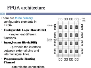
This document provides information about reversible logic gates and their application in field programmable gate arrays (FPGAs). It describes the design of reversible 4-to-1 multiplexers, D latches, and master-slave flip flops using novel reversible gates. The proposed reversible designs have fewer components and lower cost compared to existing irreversible circuit designs. In conclusion, the document presents the first proposed design of a reversible logic block for FPGAs, improving the efficiency of sequential circuits used to realize FPGA functions.