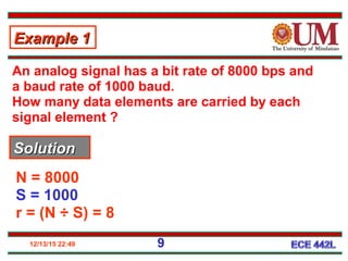
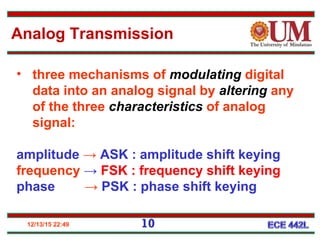
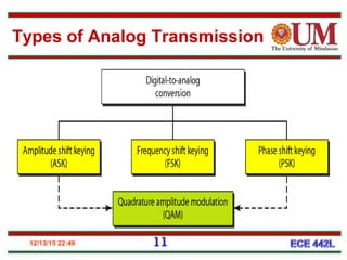
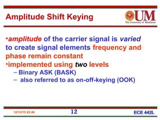
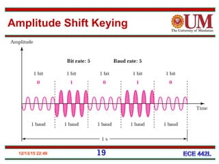
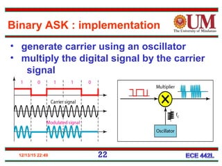
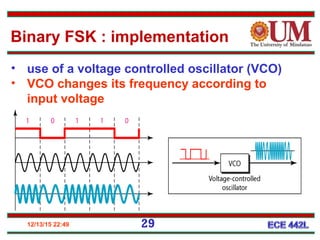
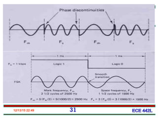
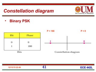
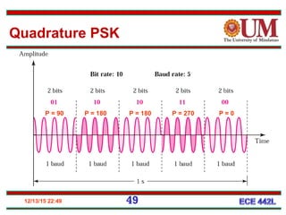
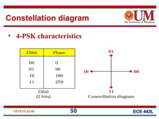
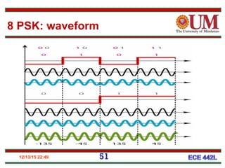
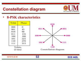
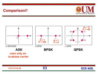
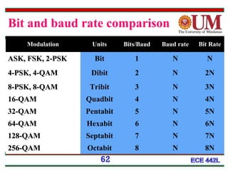
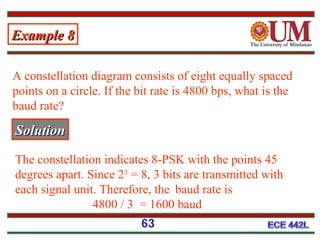
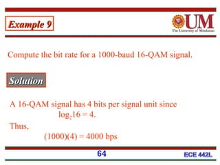
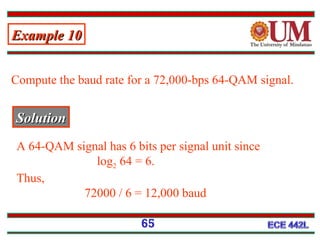
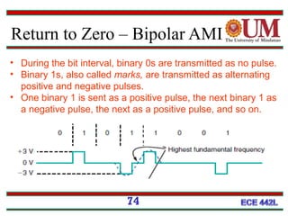
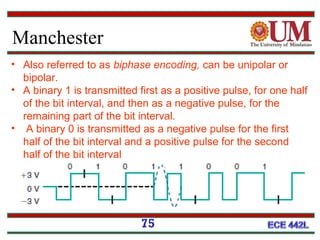
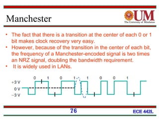
DIgItal CommunICatIon
ECE 421l
2013
II. Bandpass Modulation
12/13/15 22:49 2
Types of Signal Transmission
Digital transmission
•Baseband data
transmission
•Data is directly transmitted
without carrier
•Suitable for short distance
transmission
Analog Transmission
• Passband data
transmission
• Data modulates high
frequency sinusoidal
carrier
• Suitable for long
distance transmission
12/13/15 22:49 3
Analog Transmission
12/13/15 22:49 4
Data element vs. Signal element
• a data element (bit) is the smallest
quantity, that can represent a piece of
information
• a signal element (vehicle / carrier)
carries data elements (passengers)
- can contain one or more bits
12/13/15 22:49 5
bit rate : the number of data elements
transmitted per second
baud rate : the number of signal
elements transmitted per second
Bit and Baud
Bit and Baud
6
12/13/15 22:49 7
Data (bit) rate vs. signal (baud) rate
• r is the number of data elements carried
by each signal element
• N = bit rate and S = baud rate
• S = N x (1 ÷ r) in bauds
• r = log2 L
where L is the type of signal element
in analog transmission, S ≤ r
12/13/15 22:49 8
An analog signal carries 4 bits per signal
element. If 1000 signal elements are
transmitted per second, find the bit rate.
r = 4
S = 1000
N = S x r = 4000 bps
Example 1Example 1
SolutionSolution
12/13/15 22:49 9
An analog signal has a bit rate of 8000 bps and
a baud rate of 1000 baud.
How many data elements are carried by each
signal element ?
N = 8000
S = 1000
r = (N ÷ S) = 8
Example 1Example 1
SolutionSolution
12/13/15 22:49 10
Analog Transmission
• three mechanisms of modulating digital
data into an analog signal by altering any
of the three characteristics of analog
signal:
amplitude → ASK : amplitude shift keying
frequency → FSK : frequency shift keying
phase → PSK : phase shift keying
12/13/15 22:49 11
Types of Analog Transmission
12/13/15 22:49 12
Amplitude Shift Keying
•amplitude of the carrier signal is varied
to create signal elements frequency and
phase remain constant
•implemented using two levels
– Binary ASK (BASK)
– also referred to as on-off-keying (OOK)
Amplitude Shift Keying
13
12/13/15 22:49 14
Amplitude Shift Keying
• modulation produces
aperiodic composite
signal, with continuous
set of frequencies
• bandwidth is proportional
to the signal ( baud ) rate
12/13/15 22:49
• In data communications, it is normally to use full-duplex links
with communication in both directions.
• bandwidth is divided into two with two carrier frequencies, as
• The figure shows the positions of two carrier frequencies
and the bandwidths.
• The available bandwidth for each direction is now 50 kHz,
which leaves us with a data rate of 25 kbps in each direction.
Amplitude Shift Keying
16
12/13/15 22:49 18
4, 8,16 … amplitudes can be used for the
signal
data can be modulated using 2, 3, 4 …
bits at a time
in such cases, r = 2, r = 3, r = 4, ….
Multi-level ASK (MASK)
12/13/15 22:49 19
Amplitude Shift Keying
Example 3Example 3
Find the minimum bandwidth for an ASK signal
transmitting at 2000 bps. The transmission mode is
half-duplex.
SolutionSolution
• In ASK: baud rate = bit rate Therefore baud
rate = 2000bps.
• minimum bandwidth =baud rate. Therefore,
minimum bandwidth = 2000 Hz.
12/13/15 22:49 20
Given a bandwidth of 5000 Hz for an ASK signal,
what are the baud rate and bit rate?
• baud rate = bandwidth, Therefore, baud rate =
5000 bps.
• baud rate = bit rate, Therefore, bit rate = 5000
bps.
Example 4Example 4
SolutionSolution
12/13/15 22:49 21
12/13/15 22:49 22
• generate carrier using an oscillator
• multiply the digital signal by the carrier
signal
Binary ASK : implementation
Merits and Demerits
• Values represented by different amplitudes of
carrier
• Usually, one amplitude is zero
– i.e. presence and absence of carrier is used
• Susceptible to sudden gain changes
• Inefficient
• Typically used up to 1200bps on voice grade
lines
• Used over optical fiber
23
12/13/15 22:49 24
• frequency of the carrier signal is varied
to represent data
• frequency of the modulated signal is
constant for the duration of one signal
element and changes for the next
signal element if the data element
changes amplitude
• Amplitude and Phase remain constant
for all signal elements
Frequency Shift Keying
12/13/15 22:49 25
• implemented using two carrier frequencies:
• F1,(space frequency) data elements 0
• f2, (mark frequency) data elements 1
• both f1 and f2 are 2Δf apart
Binary FSK
12/13/15 22:49 26
0 → regular frequency ; 1 → increased frequency
Binary FSK
12/13/15 22:49 27
Modulation Index
∆f = frequency deviation
fa = modulating frequency
fb = input bit rate
12/13/15 22:49 29
• use of a voltage controlled oscillator (VCO)
• VCO changes its frequency according to
input voltage
Binary FSK : implementation
12/13/15 22:49 30
Minimum Shift Keying FSK
• Continuous-phase frequency shift keying
• Mark and Space frequency are synchronized
with the input bit rate.
• Mark and Space frequency are selected such
that they are separated from the center
frequency by an exact odd multiple of one-
half of the bit rate
12/13/15 22:49 31
Minimum Shift Keying FSK
32
• it requires synchronizing circuits and is
therefore more expensive to implement.
Merits and Demerits
5.33
We have an available bandwidth of 100 kHz
which spans from 200 to 300 kHz. What should
be the carrier frequency and the bit rate if we
modulated our data by using FSK with d = 1?
Fc = 250 kHz.(midband) We choose 2 f to be 50 kHz;Δ
Example 6Example 6
SolutionSolution
33
5.34
We need to send data 3 bits at a time at a bit rate of 3
Mbps. The carrier frequency is 10 MHz. Calculate the
number of levels (different frequencies), the baud rate,
and the bandwidth.
Example 7Example 7
SolutionSolution
34
5.35
Bandwidthof Multi level FSK
35
Merits and Demerits
• Values represented by different frequencies (near
carrier)
• Less susceptible to error than ASK
• Typically used up to 1200bps on voice grade
lines
• High frequency radio
• Even higher frequency on LANs using co-ax
• Used in cordless and paging system
36
12/13/15 22:49 37
• Phase of the carrier signal is varied to
represent two or more different signal
elements
• amplitude and frequency remain
constant
Phase Shift Keying
12/13/15 22:49 38
• helps defining the amplitude and phase
of a signal element
• signal element type is represented as a
dot
• the bit or combination of bits it carries
is written next to the dot
• diagram has two axes
X-axis → related to the in-phase carrier
Y-axis → related to the quadrature carrier
Constellation diagram
12/13/15 22:49 39
Constellation diagram
12/13/15 22:49 40
phase 0
o
→ 1 bit ; phase 180
o
→ 0 bit
bandwidth requirement is the same as that of ASK
phase = 0o
phase =180o
Binary PSK
12/13/15 22:49 41
P = 0P = 180
• Binary PSK
Constellation diagram
12/13/15 22:49 42
Merits
(a) less susceptible to noise
(b) requires only one carrier
(less bandwidth)
Binary PSK
12/13/15 22:49 43
the digital signal used here is polar NRZ
Binary PSK : implementation
Balanced Modulator
44
45
46
M-ary Encoding
• M represents the number of
possible of condition
 Ex. M= 4, 8
12/13/15 22:49 47
• use of two bits at a time in each signal
element → decrease of baud rate →
reduction of required bandwidth
• uses two separate BPSK modulations :
one in-phase and the other out-of-phase
(quadrature)
Quadrature PSK
12/13/15 22:49 48
serial to
parallel
converter
serial to parallel converter sends one bit to one
modulator and the next bit to the other modulator
Quadrature PSK: implementation
12/13/15 22:49 49
P = 90 P = 180 P = 180 P = 270 P = 0
Quadrature PSK
50
• 4-PSK characteristics
Constellation diagram
12/13/15 22:49
12/13/15 22:49 51
8 PSK: waveform
• 8-PSK characteristics
12/13/15 22:49
Constellation diagram
52
12/13/15 22:49 53
ASK BPSK QPSK
uses only an
in-phase carrier
A = 1
P = 0
A = 1
P = 180
A = √2
P = +45
Comparison!!
12/13/15 22:49 54
Differential PSK
– Phase shifted relative to previous
transmission rather than some
reference signal
– eliminates the need for the
synchronous carrier in the
demodulation process and this
has the effect of simplifying the
receiver.
– receiver only needs to detect
– phase changes.
Differential PSK
55
12/13/15 22:49 56
• small differences in phase are difficult
to detect (PSK)
• QAM works on the basis of altering two
characteristics of the carrier :
amplitude and phase
• two carriers, one in-phase and another
quadrature with two different levels are
used
Quadrature Amplitude Modulation
12/13/15 22:49 57
Quadrature Amplitude Modulation
• Uses more phase shifts than amplitude
shifts to reduce noise susceptibility
12/13/15 22:49 58
(a) 4-QAM with four signal element types
similar to ASK or OOK
(b) 4-QAM similar to QPSK
(c) 4-QAM with a signal with two positive levels
(d) 16-QAM with 8 signal levels : 4 +ve & 4 -ve
Constellation diagrams
The 4-QAM and 8-QAM constellations
59
Time domain for an 8-QAM signal
60
16-QAM constellations
61
ModulationModulation UnitsUnits Bits/BaudBits/Baud Baud rateBaud rate Bit Rate
ASK, FSK, 2-PSKASK, FSK, 2-PSK Bit 1 N N
4-PSK, 4-QAM4-PSK, 4-QAM Dibit 2 N 2N
8-PSK, 8-QAM8-PSK, 8-QAM Tribit 3 N 3N
16-QAM16-QAM Quadbit 4 N 4N
32-QAM32-QAM Pentabit 5 N 5N
64-QAM64-QAM Hexabit 6 N 6N
128-QAM128-QAM Septabit 7 N 7N
256-QAM256-QAM Octabit 8 N 8N
62
Bit and baud rate comparison
Example 8Example 8
A constellation diagram consists of eight equally spaced
points on a circle. If the bit rate is 4800 bps, what is the
baud rate?
SolutionSolution
The constellation indicates 8-PSK with the points 45
degrees apart. Since 23
= 8, 3 bits are transmitted with
each signal unit. Therefore, the baud rate is
4800 / 3 = 1600 baud
63
Compute the bit rate for a 1000-baud 16-QAM signal.
SolutionSolution
A 16-QAM signal has 4 bits per signal unit since
log216 = 4.
Thus,
(1000)(4) = 4000 bps
Example 9Example 9
64
Compute the baud rate for a 72,000-bps 64-QAM signal.
SolutionSolution
A 64-QAM signal has 6 bits per signal unit since
log2 64 = 6.
Thus,
72000 / 6 = 12,000 baud
Example 10Example 10
65
12/13/15 22:49 66
Digital Transmission
12/13/15 22:49 67
Digital Transmission
Digital to Digital Conversion
68
Techniques:
•Line coding
•Block coding
•Scrambling
• Also known as Line
Encoding
• Baud rate
determine the
bandwidth
Digital Transmission Methods
69
• Nonreturn to Zero
• Unipolar
• Bipolar
• Return to zero
• Unipolar
• Bipolar
• Bipolar-AMI
• Manchester
Nonreturn to Zero
70
• the signal remains at the binary level assigned to it for the
entire bit time.
• the voltage does not return to zero during the binary 1
interval
• normally generated inside computers, at low speeds, when
asynchronous transmission is being used.
Nonreturn to Zero - Bipolar
71
• A bipolar NRZ signal has two polarities, positive and
negative.
• The voltage levels are +12 and -12 V.
• The popular RS-232 serial computer interface uses bipolar
NRZ, where a binary 1 is a negative voltage between -3 and
-25 V and a binary 0 is a voltage between +3 and +25 V.
Return to Zero - Unipolar
72
• The binary 1 level occurs for 50 percent of the bit interval,
and the remaining bit interval is zero.
• Only one polarity level is used.
• Pulses occur only when a binary 1 is transmitted; no pulse is
transmitted for a binary 0.
Return to Zero - Bipolar
73
• A 50 percent bit interval 13-V pulse is transmitted during a
binary 1, and a 23-V pulse is transmitted for a binary 0.
• Because there is one clearly discernible pulse per bit, it is
extremely easy to derive the clock from the transmitted data.
• For that reason, bipolar RZ is preferred over unipolar RZ.
Return to Zero – Bipolar AMI
74
• During the bit interval, binary 0s are transmitted as no pulse.
• Binary 1s, also called marks, are transmitted as alternating
positive and negative pulses.
• One binary 1 is sent as a positive pulse, the next binary 1 as
a negative pulse, the next as a positive pulse, and so on.
Manchester
75
• Also referred to as biphase encoding, can be unipolar or
bipolar.
• A binary 1 is transmitted first as a positive pulse, for one half
of the bit interval, and then as a negative pulse, for the
remaining part of the bit interval.
• A binary 0 is transmitted as a negative pulse for the first
half of the bit interval and a positive pulse for the second
half of the bit interval
Manchester
76
• The fact that there is a transition at the center of each 0 or 1
bit makes clock recovery very easy.
• However, because of the transition in the center of each bit,
the frequency of a Manchester-encoded signal is two times
an NRZ signal, doubling the bandwidth requirement.
• It is widely used in LANs.
Reference
• Data Communication
– by Forouzan
• Advance Electronic Communication
– by Robert Tomasi
• Principles of Electronic Communication Systems
– Louis E. Frenzel Jr.
77

Digital Communication 2

  • 1.
  • 2.
    12/13/15 22:49 2 Typesof Signal Transmission Digital transmission •Baseband data transmission •Data is directly transmitted without carrier •Suitable for short distance transmission Analog Transmission • Passband data transmission • Data modulates high frequency sinusoidal carrier • Suitable for long distance transmission
  • 3.
  • 4.
    12/13/15 22:49 4 Dataelement vs. Signal element • a data element (bit) is the smallest quantity, that can represent a piece of information • a signal element (vehicle / carrier) carries data elements (passengers) - can contain one or more bits
  • 5.
    12/13/15 22:49 5 bitrate : the number of data elements transmitted per second baud rate : the number of signal elements transmitted per second Bit and Baud
  • 6.
  • 7.
    12/13/15 22:49 7 Data(bit) rate vs. signal (baud) rate • r is the number of data elements carried by each signal element • N = bit rate and S = baud rate • S = N x (1 ÷ r) in bauds • r = log2 L where L is the type of signal element in analog transmission, S ≤ r
  • 8.
    12/13/15 22:49 8 Ananalog signal carries 4 bits per signal element. If 1000 signal elements are transmitted per second, find the bit rate. r = 4 S = 1000 N = S x r = 4000 bps Example 1Example 1 SolutionSolution
  • 9.
    12/13/15 22:49 9 Ananalog signal has a bit rate of 8000 bps and a baud rate of 1000 baud. How many data elements are carried by each signal element ? N = 8000 S = 1000 r = (N ÷ S) = 8 Example 1Example 1 SolutionSolution
  • 10.
    12/13/15 22:49 10 AnalogTransmission • three mechanisms of modulating digital data into an analog signal by altering any of the three characteristics of analog signal: amplitude → ASK : amplitude shift keying frequency → FSK : frequency shift keying phase → PSK : phase shift keying
  • 11.
    12/13/15 22:49 11 Typesof Analog Transmission
  • 12.
    12/13/15 22:49 12 AmplitudeShift Keying •amplitude of the carrier signal is varied to create signal elements frequency and phase remain constant •implemented using two levels – Binary ASK (BASK) – also referred to as on-off-keying (OOK)
  • 13.
  • 14.
    12/13/15 22:49 14 AmplitudeShift Keying • modulation produces aperiodic composite signal, with continuous set of frequencies • bandwidth is proportional to the signal ( baud ) rate
  • 15.
    12/13/15 22:49 • Indata communications, it is normally to use full-duplex links with communication in both directions. • bandwidth is divided into two with two carrier frequencies, as • The figure shows the positions of two carrier frequencies and the bandwidths. • The available bandwidth for each direction is now 50 kHz, which leaves us with a data rate of 25 kbps in each direction. Amplitude Shift Keying 16
  • 16.
    12/13/15 22:49 18 4,8,16 … amplitudes can be used for the signal data can be modulated using 2, 3, 4 … bits at a time in such cases, r = 2, r = 3, r = 4, …. Multi-level ASK (MASK)
  • 17.
  • 18.
    Example 3Example 3 Findthe minimum bandwidth for an ASK signal transmitting at 2000 bps. The transmission mode is half-duplex. SolutionSolution • In ASK: baud rate = bit rate Therefore baud rate = 2000bps. • minimum bandwidth =baud rate. Therefore, minimum bandwidth = 2000 Hz. 12/13/15 22:49 20
  • 19.
    Given a bandwidthof 5000 Hz for an ASK signal, what are the baud rate and bit rate? • baud rate = bandwidth, Therefore, baud rate = 5000 bps. • baud rate = bit rate, Therefore, bit rate = 5000 bps. Example 4Example 4 SolutionSolution 12/13/15 22:49 21
  • 20.
    12/13/15 22:49 22 •generate carrier using an oscillator • multiply the digital signal by the carrier signal Binary ASK : implementation
  • 21.
    Merits and Demerits •Values represented by different amplitudes of carrier • Usually, one amplitude is zero – i.e. presence and absence of carrier is used • Susceptible to sudden gain changes • Inefficient • Typically used up to 1200bps on voice grade lines • Used over optical fiber 23
  • 22.
    12/13/15 22:49 24 •frequency of the carrier signal is varied to represent data • frequency of the modulated signal is constant for the duration of one signal element and changes for the next signal element if the data element changes amplitude • Amplitude and Phase remain constant for all signal elements Frequency Shift Keying
  • 23.
    12/13/15 22:49 25 •implemented using two carrier frequencies: • F1,(space frequency) data elements 0 • f2, (mark frequency) data elements 1 • both f1 and f2 are 2Δf apart Binary FSK
  • 24.
    12/13/15 22:49 26 0→ regular frequency ; 1 → increased frequency Binary FSK
  • 25.
    12/13/15 22:49 27 ModulationIndex ∆f = frequency deviation fa = modulating frequency fb = input bit rate
  • 26.
    12/13/15 22:49 29 •use of a voltage controlled oscillator (VCO) • VCO changes its frequency according to input voltage Binary FSK : implementation
  • 27.
    12/13/15 22:49 30 MinimumShift Keying FSK • Continuous-phase frequency shift keying • Mark and Space frequency are synchronized with the input bit rate. • Mark and Space frequency are selected such that they are separated from the center frequency by an exact odd multiple of one- half of the bit rate
  • 28.
    12/13/15 22:49 31 MinimumShift Keying FSK
  • 29.
    32 • it requiressynchronizing circuits and is therefore more expensive to implement. Merits and Demerits
  • 30.
    5.33 We have anavailable bandwidth of 100 kHz which spans from 200 to 300 kHz. What should be the carrier frequency and the bit rate if we modulated our data by using FSK with d = 1? Fc = 250 kHz.(midband) We choose 2 f to be 50 kHz;Δ Example 6Example 6 SolutionSolution 33
  • 31.
    5.34 We need tosend data 3 bits at a time at a bit rate of 3 Mbps. The carrier frequency is 10 MHz. Calculate the number of levels (different frequencies), the baud rate, and the bandwidth. Example 7Example 7 SolutionSolution 34
  • 32.
  • 33.
    Merits and Demerits •Values represented by different frequencies (near carrier) • Less susceptible to error than ASK • Typically used up to 1200bps on voice grade lines • High frequency radio • Even higher frequency on LANs using co-ax • Used in cordless and paging system 36
  • 34.
    12/13/15 22:49 37 •Phase of the carrier signal is varied to represent two or more different signal elements • amplitude and frequency remain constant Phase Shift Keying
  • 35.
    12/13/15 22:49 38 •helps defining the amplitude and phase of a signal element • signal element type is represented as a dot • the bit or combination of bits it carries is written next to the dot • diagram has two axes X-axis → related to the in-phase carrier Y-axis → related to the quadrature carrier Constellation diagram
  • 36.
  • 37.
    12/13/15 22:49 40 phase0 o → 1 bit ; phase 180 o → 0 bit bandwidth requirement is the same as that of ASK phase = 0o phase =180o Binary PSK
  • 38.
    12/13/15 22:49 41 P= 0P = 180 • Binary PSK Constellation diagram
  • 39.
    12/13/15 22:49 42 Merits (a)less susceptible to noise (b) requires only one carrier (less bandwidth) Binary PSK
  • 40.
    12/13/15 22:49 43 thedigital signal used here is polar NRZ Binary PSK : implementation
  • 41.
  • 42.
  • 43.
    46 M-ary Encoding • Mrepresents the number of possible of condition  Ex. M= 4, 8
  • 44.
    12/13/15 22:49 47 •use of two bits at a time in each signal element → decrease of baud rate → reduction of required bandwidth • uses two separate BPSK modulations : one in-phase and the other out-of-phase (quadrature) Quadrature PSK
  • 45.
    12/13/15 22:49 48 serialto parallel converter serial to parallel converter sends one bit to one modulator and the next bit to the other modulator Quadrature PSK: implementation
  • 46.
    12/13/15 22:49 49 P= 90 P = 180 P = 180 P = 270 P = 0 Quadrature PSK
  • 47.
  • 48.
    12/13/15 22:49 51 8PSK: waveform
  • 49.
    • 8-PSK characteristics 12/13/1522:49 Constellation diagram 52
  • 50.
    12/13/15 22:49 53 ASKBPSK QPSK uses only an in-phase carrier A = 1 P = 0 A = 1 P = 180 A = √2 P = +45 Comparison!!
  • 51.
    12/13/15 22:49 54 DifferentialPSK – Phase shifted relative to previous transmission rather than some reference signal – eliminates the need for the synchronous carrier in the demodulation process and this has the effect of simplifying the receiver.
  • 52.
    – receiver onlyneeds to detect – phase changes. Differential PSK 55
  • 53.
    12/13/15 22:49 56 •small differences in phase are difficult to detect (PSK) • QAM works on the basis of altering two characteristics of the carrier : amplitude and phase • two carriers, one in-phase and another quadrature with two different levels are used Quadrature Amplitude Modulation
  • 54.
    12/13/15 22:49 57 QuadratureAmplitude Modulation • Uses more phase shifts than amplitude shifts to reduce noise susceptibility
  • 55.
    12/13/15 22:49 58 (a)4-QAM with four signal element types similar to ASK or OOK (b) 4-QAM similar to QPSK (c) 4-QAM with a signal with two positive levels (d) 16-QAM with 8 signal levels : 4 +ve & 4 -ve Constellation diagrams
  • 56.
    The 4-QAM and8-QAM constellations 59
  • 57.
    Time domain foran 8-QAM signal 60
  • 58.
  • 59.
    ModulationModulation UnitsUnits Bits/BaudBits/BaudBaud rateBaud rate Bit Rate ASK, FSK, 2-PSKASK, FSK, 2-PSK Bit 1 N N 4-PSK, 4-QAM4-PSK, 4-QAM Dibit 2 N 2N 8-PSK, 8-QAM8-PSK, 8-QAM Tribit 3 N 3N 16-QAM16-QAM Quadbit 4 N 4N 32-QAM32-QAM Pentabit 5 N 5N 64-QAM64-QAM Hexabit 6 N 6N 128-QAM128-QAM Septabit 7 N 7N 256-QAM256-QAM Octabit 8 N 8N 62 Bit and baud rate comparison
  • 60.
    Example 8Example 8 Aconstellation diagram consists of eight equally spaced points on a circle. If the bit rate is 4800 bps, what is the baud rate? SolutionSolution The constellation indicates 8-PSK with the points 45 degrees apart. Since 23 = 8, 3 bits are transmitted with each signal unit. Therefore, the baud rate is 4800 / 3 = 1600 baud 63
  • 61.
    Compute the bitrate for a 1000-baud 16-QAM signal. SolutionSolution A 16-QAM signal has 4 bits per signal unit since log216 = 4. Thus, (1000)(4) = 4000 bps Example 9Example 9 64
  • 62.
    Compute the baudrate for a 72,000-bps 64-QAM signal. SolutionSolution A 64-QAM signal has 6 bits per signal unit since log2 64 = 6. Thus, 72000 / 6 = 12,000 baud Example 10Example 10 65
  • 63.
  • 64.
  • 65.
    Digital to DigitalConversion 68 Techniques: •Line coding •Block coding •Scrambling • Also known as Line Encoding • Baud rate determine the bandwidth
  • 66.
    Digital Transmission Methods 69 •Nonreturn to Zero • Unipolar • Bipolar • Return to zero • Unipolar • Bipolar • Bipolar-AMI • Manchester
  • 67.
    Nonreturn to Zero 70 •the signal remains at the binary level assigned to it for the entire bit time. • the voltage does not return to zero during the binary 1 interval • normally generated inside computers, at low speeds, when asynchronous transmission is being used.
  • 68.
    Nonreturn to Zero- Bipolar 71 • A bipolar NRZ signal has two polarities, positive and negative. • The voltage levels are +12 and -12 V. • The popular RS-232 serial computer interface uses bipolar NRZ, where a binary 1 is a negative voltage between -3 and -25 V and a binary 0 is a voltage between +3 and +25 V.
  • 69.
    Return to Zero- Unipolar 72 • The binary 1 level occurs for 50 percent of the bit interval, and the remaining bit interval is zero. • Only one polarity level is used. • Pulses occur only when a binary 1 is transmitted; no pulse is transmitted for a binary 0.
  • 70.
    Return to Zero- Bipolar 73 • A 50 percent bit interval 13-V pulse is transmitted during a binary 1, and a 23-V pulse is transmitted for a binary 0. • Because there is one clearly discernible pulse per bit, it is extremely easy to derive the clock from the transmitted data. • For that reason, bipolar RZ is preferred over unipolar RZ.
  • 71.
    Return to Zero– Bipolar AMI 74 • During the bit interval, binary 0s are transmitted as no pulse. • Binary 1s, also called marks, are transmitted as alternating positive and negative pulses. • One binary 1 is sent as a positive pulse, the next binary 1 as a negative pulse, the next as a positive pulse, and so on.
  • 72.
    Manchester 75 • Also referredto as biphase encoding, can be unipolar or bipolar. • A binary 1 is transmitted first as a positive pulse, for one half of the bit interval, and then as a negative pulse, for the remaining part of the bit interval. • A binary 0 is transmitted as a negative pulse for the first half of the bit interval and a positive pulse for the second half of the bit interval
  • 73.
    Manchester 76 • The factthat there is a transition at the center of each 0 or 1 bit makes clock recovery very easy. • However, because of the transition in the center of each bit, the frequency of a Manchester-encoded signal is two times an NRZ signal, doubling the bandwidth requirement. • It is widely used in LANs.
  • 74.
    Reference • Data Communication –by Forouzan • Advance Electronic Communication – by Robert Tomasi • Principles of Electronic Communication Systems – Louis E. Frenzel Jr. 77