Modulation is the process of varying one or more characteristics of a high-frequency carrier signal based on an information signal that contains the message to be transmitted. Some key points:
1. Modulation is necessary to transmit digital data over analog mediums like phone lines or wireless signals. It converts the digital data into an analog format suitable for transmission.
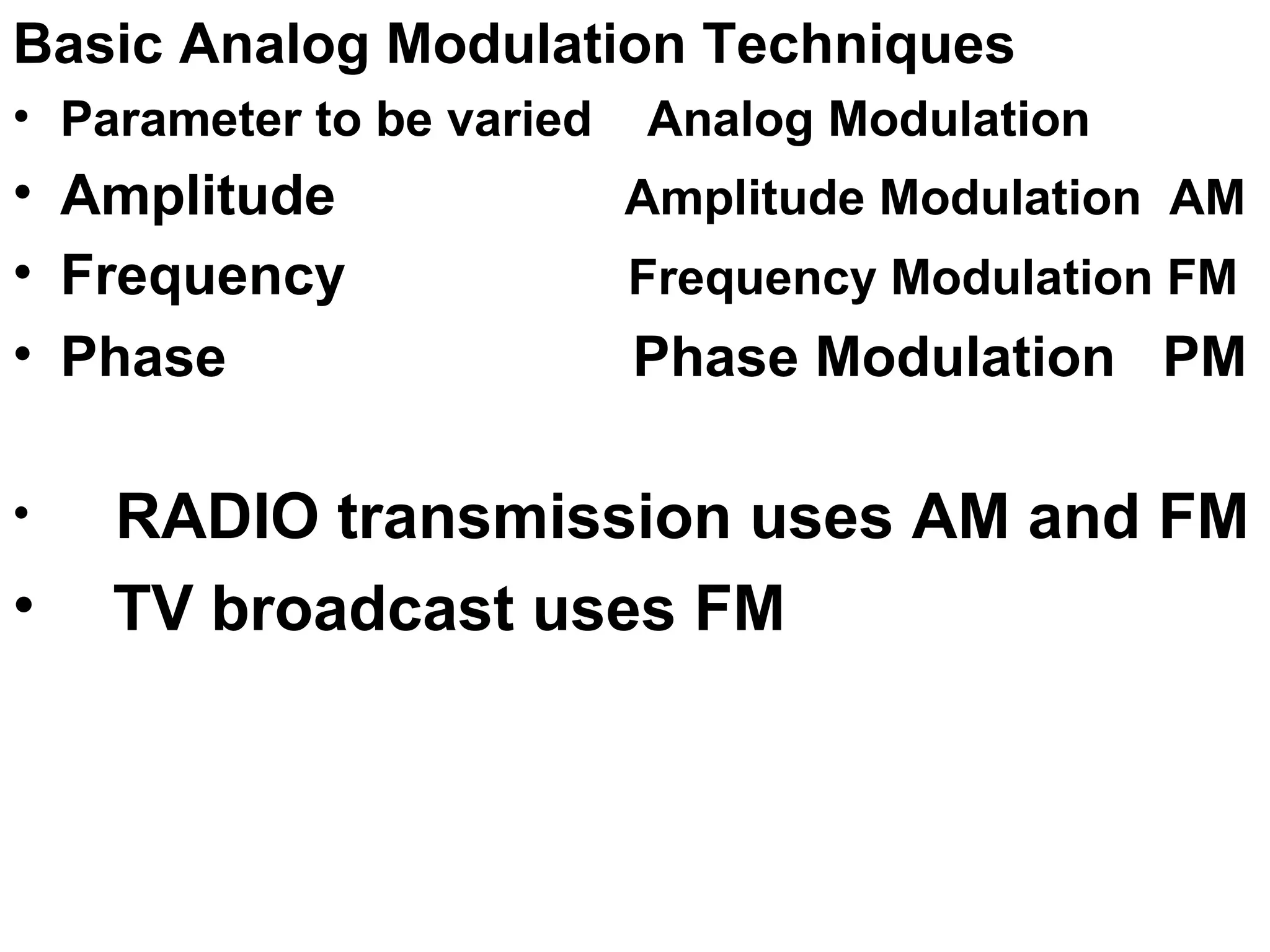
2. Common analog modulation techniques vary the amplitude, frequency, or phase of the carrier signal, while digital modulation techniques include amplitude-shift keying, frequency-shift keying, and phase-shift keying.
3. More advanced techniques like quadrature amplitude modulation vary both the amplitude and phase of the carrier simultaneously to transmit more data using a given bandwidth


![2[1].1 data transmission](https://cdn.slidesharecdn.com/ss_thumbnails/21-1-datatransmission-111203164944-phpapp01-thumbnail.jpg?width=640&height=640&fit=bounds)